 Tweet
Tweet
Am Back!
Hello to All,
Thanks Ewizard...it was exactly My Cache...besides I deleted history, cookies, brownies and chocolate chips...
Machine great run there!!...Your Generator runs excellente!!
Bravo Man, way to wind'em!!
I could leave you here and you sure will train all this guys...
Guys, about the winding mode...I display it clearly on My Asymmetric Winding Part 1... video...
I always use this Method to Wind ALL My Machines...and as you all know...they ALL work...
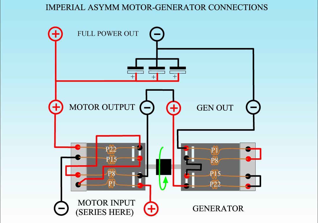
Now I follow the Positive Direction from the Positive Wire from the Positive Side Commutator...towards my fingers...sometimes "I" Direction tends to confusion...So I made it the way I do it below guiding by Positive (+) Side Comm..
[IMG]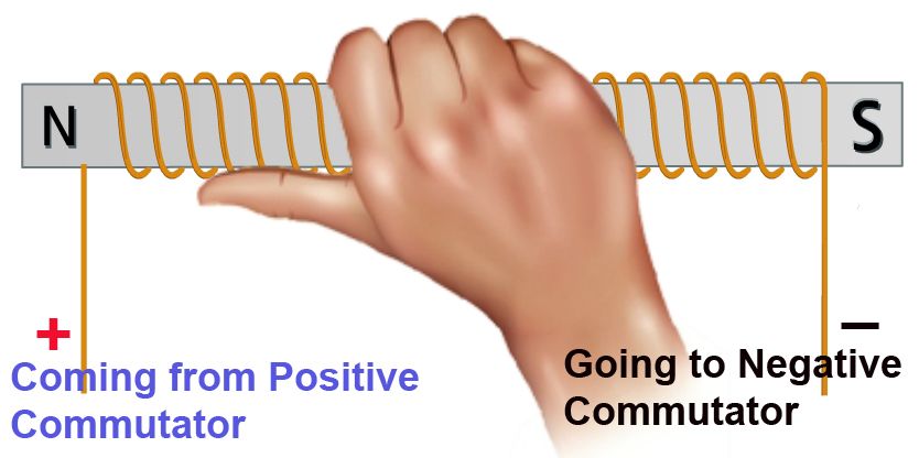 [/IMG]
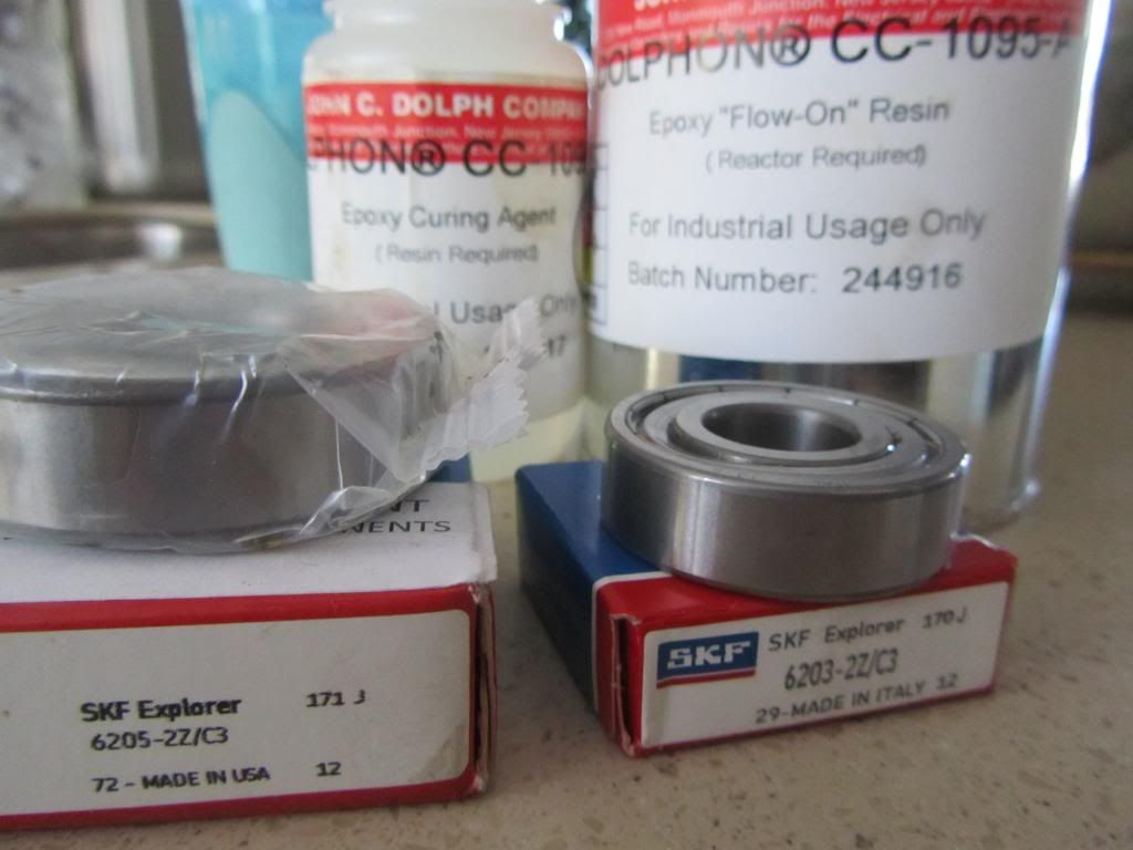
Now, That Coil shown there is a WHOLE PAIR ...in our Imperial (for example), Meaning it CONTAINS P1 South and P1 North...now, use your Imagination... to virtually "bend" that Steel Bar...in a "V" Shape and make them Your Armature Groups of Poles to be wounded N & S...
And that Applies to every single model I have displayed here...except the Three Pole...that is just a STRAIGHT COIL for each Pole, and ALL South are aiming towards shaft...
Thanks John for clearing this concepts...and reminding them of my winding video...and YES...IF You turn that Armature Upside down...and start winding from Negative side...Motor will NOT RUN...So always keep a Positive commutator UP...as a reference to your winding start point for every Pair there.
Regards
Ufopolitics
Hello to All,
Thanks Ewizard...it was exactly My Cache...besides I deleted history, cookies, brownies and chocolate chips...
Machine great run there!!...Your Generator runs excellente!!
Bravo Man, way to wind'em!!
I could leave you here and you sure will train all this guys...
Guys, about the winding mode...I display it clearly on My Asymmetric Winding Part 1... video...
I always use this Method to Wind ALL My Machines...and as you all know...they ALL work...
Now I follow the Positive Direction from the Positive Wire from the Positive Side Commutator...towards my fingers...sometimes "I" Direction tends to confusion...So I made it the way I do it below guiding by Positive (+) Side Comm..
[IMG]
[/IMG]Now, That Coil shown there is a WHOLE PAIR ...in our Imperial (for example), Meaning it CONTAINS P1 South and P1 North...now, use your Imagination... to virtually "bend" that Steel Bar...in a "V" Shape and make them Your Armature Groups of Poles to be wounded N & S...
And that Applies to every single model I have displayed here...except the Three Pole...that is just a STRAIGHT COIL for each Pole, and ALL South are aiming towards shaft...
Thanks John for clearing this concepts...and reminding them of my winding video...and YES...IF You turn that Armature Upside down...and start winding from Negative side...Motor will NOT RUN...So always keep a Positive commutator UP...as a reference to your winding start point for every Pair there.
Regards
Ufopolitics
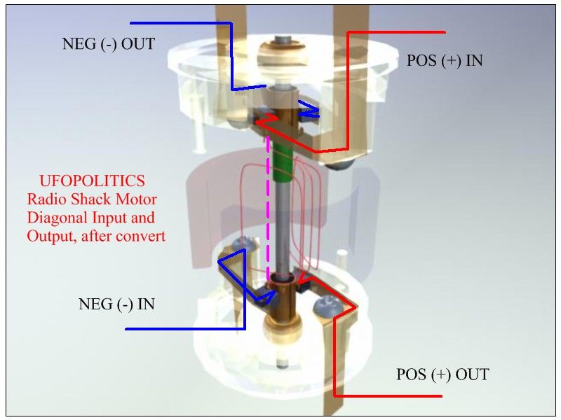
 ...Then you will be using very little Input pulsed to that Coil...using the Radiant Amplified Higher Frequencies...and run that Motor Cool...No Sparks...and very "smooth"...

 [/IMG]
 [/IMG]
")


 But the motor doesn't really care it will just turn the other way?

 [/IMG]
 [/IMG]
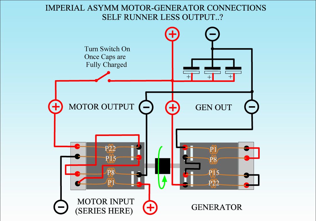 [/IMG]
Comment