Announcement

Collapse
No announcement yet.

My Asymmetric Electrodynamic Machines

Collapse
X
 
  • Filter
  • Time
  • Show
Clear All
new posts

  • goldmine wire lengths

    @Sampojo

    The goldmine motors that I wound were with AWG30 18'6'' for total length which results in 2.5 ohms resistance. When I wound the AN1, I measured 9'3" and put a tape marker like when winding the Y winding. Then without cutting the wire measured another 9'3" for the second coil. Sounds like an interesting project.

    Cheers

    Garry

    Comment


    • There was another high pitch noise before and after the motor connection/disconnection.

      Could the varying frequency be a harmonic ?

      Also, to use sound as a tuning method, I would solid mount the motor and clear the bench. You had stuff jumping to the beat and the motor mount was mobile.

      Happy Hunting

      mark

      Comment


      • Originally posted by sampojo View Post

        EDIT PS: in reply to Ufo below, I think I need a few drops of epoxy around my bearing housing, its fit is too sloppy in the endplate seat I made and it can come very loose, and I think mostly responsible for the pulsing oscillation of the rpms, along with a less than perfect balance in the rotor...
        Hey Sam,

        That could be -in part- a mechanical issue like you are saying...however, mechanical errors are not normally that perfect in repetition at almost identical times...I bet your sound editor will write it as an almost perfect sinewave.

        I would rather concentrate in building the All North Rotor for that casing...and now that you have the whole spec's from Garry...you could do it without ANY excuse...

        Be good!

        Originally posted by HuntingRoss View Post
        There was another high pitch noise before and after the motor connection/disconnection.

        Could the varying frequency be a harmonic ?
        Hey Mark,

        It could be...however at disconnection I notice the little rotor kept spinning freely...so I would not consider start or end noise as due to a mechanical problem.

        Also, to use sound as a tuning method, I would solid mount the motor and clear the bench. You had stuff jumping to the beat and the motor mount was mobile.

        Happy Hunting

        mark
        Yes agree there...and even using some rubber damping mount bushings or whatever cushioning/absorbing material will help to reduce vibration...


        Ufopolitics
        Principles for the Development of a Complete Mind: Study the science of art. Study the art of science. Develop your senses- especially learn how to see. Realize that everything connects to everything else.― Leonardo da Vinci

        Comment


        • High pitch end noise

          Wow, I knew I should have shut off my Imhotep battery desulfater/radiant energy charger I was running on a battery.

          But as I prep things, I can see my Pentagon motor was using 30ga., and it was stuffed full. So I won't get any relief for conventional amperage ranges in regards to heating. I can see that Garry's Goldmines are a size bigger than radio shack's. I haven't dug to deep and may have posted it back then, Mar 2013. But I believe the number will be about 12' of wire. At about 10'/ohm, you can see that it will be about 1.2 ohms. My ohm meters are detecting a woeful 2.3, not even close. If I hold it for a while the digital sampling seems to bring it down gradually. But I think it is 1.2 ohm thereabouts. Hate to do a rewire if I am off, so may dig thru the old posts and records on my PC a little bit.

          I can see that Garry was carrying a bit more of resistance, which would explain his off sweet-spot amperage of less than an ohm (EDIT: I meant to say "amp") compared to my 1.2 ohm machine pulling in 1.25-1.5A. The wire only calculated resistance for that config would be about 1.8 ohm. And I bet they ran cool too, even off the sweet spot. Incidentally my Quad UP-10 trifilar had a calculated 1.2 ohms and ran around 120degF also. And around 1.2-1.5 amps also! Guess it all figures.

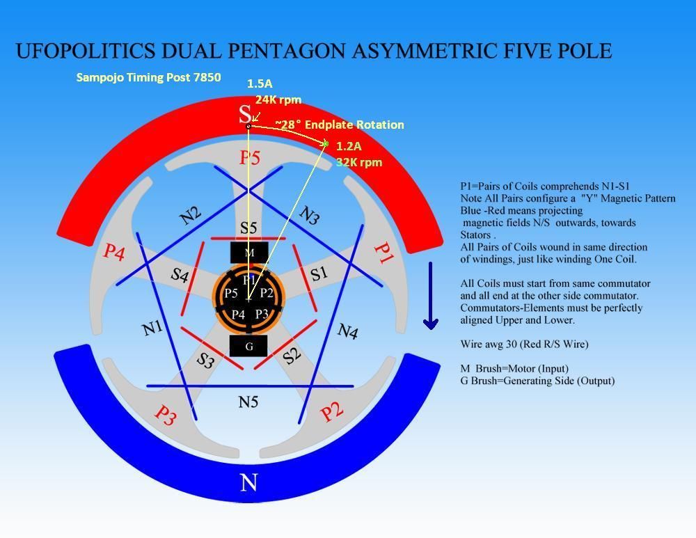
          Here is a diagram showing the timing change needed in post 7850


          So @ufo, is 120degF bad for the magnets?

          Taking an optimistic tact, running hot planning at conventional amperage might be the ticket if we get this Sweet Spot Drop On-Demand...

          Carry on, Tesla soldiers!
          Last edited by sampojo; 06-08-2015, 04:34 AM.
          Up, Up and Away

          Comment


          • Originally posted by sampojo View Post
            Wow, I knew I should have shut off my Imhotep battery desulfater/radiant energy charger I was running on a battery.

            But as I prep things, I can see my Pentagon motor was using 30ga., and it was stuffed full. So I won't get any relief for conventional amperage ranges in regards to heating. I can see that Garry's Goldmines are a size bigger than radio shack's. I haven't dug to deep and may have posted it back then, Mar 2013. But I believe the number will be about 12' of wire. At about 10'/ohm, you can see that it will be about 1.2 ohms. My ohm meters are detecting a woeful 2.3, not even close. If I hold it for a while the digital sampling seems to bring it down gradually. But I think it is 1.2 ohm thereabouts. Hate to do a rewire if I am off, so may dig thru the old posts and records on my PC a little bit.

            I can see that Garry was carrying a bit more of resistance, which would explain his off sweet-spot amperage of less than an ohm compared to my 1.2 ohm machine pulling in 1.25-1.5A. The wire only calculated resistance for that config would be about 1.8 ohm. And I bet they ran cool too, even off the sweet spot. Incidentally my Quad UP-10 trifilar had a calculated 1.2 ohms and ran around 120degF also. And around 1.2-1.5 amps also! Guess it all figures.

            Here is a diagram showing the timing change needed in post 7850


            So @ufo, is 120degF bad for the magnets?

            Taking an optimistic tact, running hot planning at conventional amperage might be the ticket if we get this Sweet Spot Drop On-Demand...

            Carry on, Tesla soldiers!

            Hey Sam,

            First...120º F is absolutely not a risky temperature for any magnet...it is equivalent to 49º C...remember water boils at 100ºC...so that is just "warm water"...temp.

            And related to your time setting above...it makes complete sense on the results...take a look below:

            [IMG][/IMG]

            If you move the Motor Brushes CW about 28º...you are firing P1 further away from North Stator, therefore you are approaching the 'Neutral' Zone which is right at stators gap. The Motor would be running on more Attract Mode. Amps will drop...but it should be weaker...not much, because the brushes movement was not that radical...which would be passing the Neutral Line.

            Your sweet spot should be very close to that position...however, there are many things that make each set up different...like type of windings and number of turns...plus any mechanical drags...magnet strength, etc,etc.

            The best way to do this adjustment is while motor is running and hooked to DMM's or Power Supply with readings...plus checking RPM's ...if your model allows that without any risks of coming apart during operation.

            Believe me...it is the best way to do it and find the sweet spot easier and faster.

            The opposite movement of the Brushes (CCW) will cause more Repulse Mode (closer to North-South respectively)...take a look below:

            [IMG][/IMG]


            Regards


            Ufopolitics
            Last edited by Ufopolitics; 06-06-2015, 01:56 PM.
            Principles for the Development of a Complete Mind: Study the science of art. Study the art of science. Develop your senses- especially learn how to see. Realize that everything connects to everything else.― Leonardo da Vinci

            Comment


            • Selecting to wind AN-1

              After a third look at the data from BOTW, AN-1 seems to be a little bit better in rpm with just a miniscule increase in amps. If it has better wide-open unloaded rpm, I say it has better torque, to get that extra rpm.

              Dang, shattered a commutator Friday, got another motor yesterday, had to pull down a tree Saturday for my solar panels installation too. Might've been winding this evening rather than building the rotor still...

              Radio Shack had a neat Xmod RC car on sale $10. I intend to teach my grandsons asym motor construction with, maybe race these, boy will they clean up!

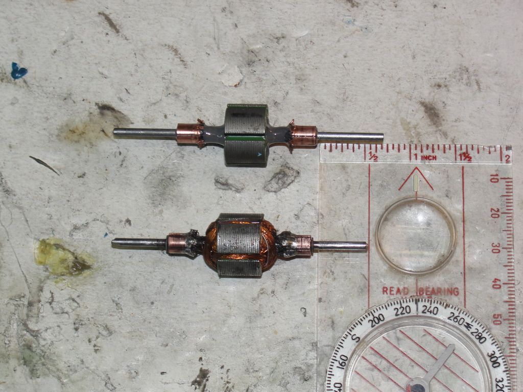
              Here is new rotor with the the Pentagon Y rotor.


              epoxy is curing.

              winding tomorrow night hopefully.

              Reran some tests on the Pent Y, got a 150degF reading once, mostly using one brush set. Turned out to be the weaker maybe, got up around 22000rpm, finally connected the second brush set, really jumped to about 28000rpm, don't usually get that much on the second. Not sure where that sweetest spot is, markings not good on the motor. Still afraid of burnning it up, but seems pretty tough. pulsing seemed to be associated with end plates too loose, giving the shaft room to move back and forth. tightening things up a bit seemed to stop it.
              Last edited by sampojo; 06-08-2015, 04:46 AM.
              Up, Up and Away

              Comment


              • Radio Shack AN-1 finito

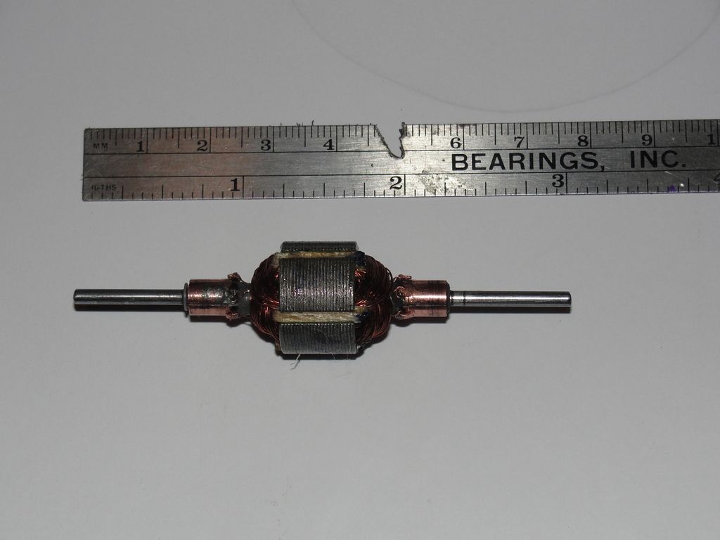
                Took a chance and ran it with only wooden hedges for a quick test, maybe got 29000 rpm on just one brush set. Here it is with a coat of epoxy on the windings. Needs to cure.


                Dreaming up a test rig... want to use a panel ammeter rather than a digital multimeter.

                Good night
                Last edited by sampojo; 06-09-2015, 05:02 AM.
                Up, Up and Away

                Comment


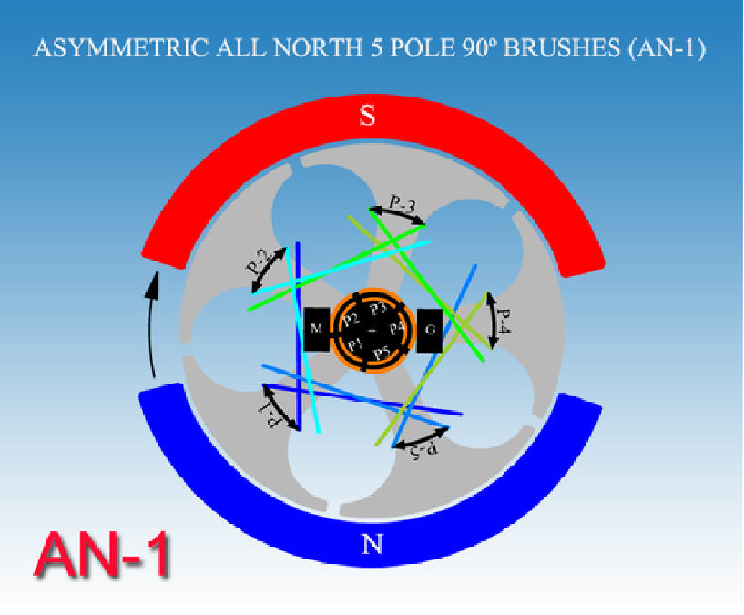
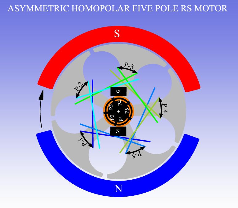
                • AN-1 vs original RS homopolar

                  Ufo, Quite the difference here. Totally missed this when it happened. Always assumed AN-1 was the same as your first homopolar radio shack creations.


                  Garry, can you post a timing diagram showing the angle of endplate rotation to hit the sweet spot, exactly how much different from the start position on the AN-1 diagram? Is it in your videos?

                  To accomplish that task, something like what I did in my Pentagon Y diagram in my post #7855

                  Starting some testing now...

                  First look, no sweet spot like we hoped, tested 8 positions, best was 31,000rpm @12.3v/0.7A
                  Last edited by sampojo; 06-10-2015, 05:04 AM.
                  Up, Up and Away

                  Comment


                  • AN-1...finding sweet spot.

                    Originally posted by sampojo View Post
                    Ufo, Quite the difference here. Totally missed this when it happened. Always assumed AN-1 was the same as your first homopolar radio shack creations.
                    Hey Sam,

                    Yes, quite a difference Huh?

                    Garry, can you post a timing diagram showing the angle of endplate rotation to hit the sweet spot, exactly how much different from the start position on the AN-1 diagram? Is it in your videos?

                    To accomplish that task, something like what I did in my Pentagon Y diagram in my post #7855
                    Garry adjusted timing more towards Attraction Mode...meaning moving Motor Brushes according to Rotation direction, in order that P1 starts firing closer to South Bisector. I would try to start from the "Neutral" position or centering P1 right at Stators Gap...then start slowly moving it towards rotation.

                    Starting some testing now...

                    First look, no sweet spot like we hoped, tested 8 positions, best was 31,000rpm @12.3v/0.7A
                    Well, that is already some pretty big improvement so far...if we compare with what you wrote on the previous test with Dual Penta...:

                    Originally posted by sampojo View Post
                    After playing with it a little bit, I found it hangs together well and tunes easily, a good platform for the unipolar experiment. I found a nice sweet spot about 20deg off the diagram setting and got some pretty astounding results, but not so much of course on the amp side, although lower. On 12v, I got the amps down to around 1.25A and the rpm up over 30,000.
                    You will eventually find that sweet spot...BUT, Remember that such low amperage...like 0.08 or 0.09 amps...is the Total Operating Amperage that your armature is using to spin...PLUS is set to Attract Mode...which is weaker than Repulse...so, I would NOT expect such a High Torque/Power at those amp levels my friend.

                    Also note on Garry's chart below the RPM's motor was developing when it was consuming 0.085 Amps at 12 Volts as well...:

                    [IMG][/IMG]

                    It was below 10,000 RPM's...while you are making it "dance" at 30,000 spins per minute...

                    Since Garry did not write any decimal values in Volts readings above...I would try to maintain supply around exactly 12.00 V or lower...like 11.85 or so until you get below 10,000 RPM's...it also have to do with Battery operating amps at that point of testing.

                    It also helps if Garry give you a resistance value from each Pair...then you make a comparison reading as well.

                    The closer you get to Garry's set up...the faster you will find that SP (Sweet Spot)


                    Good luck in your search and tests...


                    Ufopolitics

                    EDIT 1: After you find "Nemo"......it would be great to make a Pulse Feeding Test...some small 12V Oscillator, like with a 555 Timer...
                    Last edited by Ufopolitics; 06-10-2015, 12:01 PM.
                    Principles for the Development of a Complete Mind: Study the science of art. Study the art of science. Develop your senses- especially learn how to see. Realize that everything connects to everything else.― Leonardo da Vinci

                    Comment


                    • Sweet spot versus super sweet spot

                      You are right Ufo. The AN-1 amp draw is a 40% drop!!! Pretty huge. Definitely had a sweet spot just not a "super sweet spot". Thinking about a test Rig as you suggest to allow turning with motor operation. That would give me better control and more granularity in order to find that "SSP". I estimate that I was moving the endplates 6-12 deg per adjustment. A nice old-fashioned panel and meter would be better to take amperage data then a digital VOM, judging by the way it fluctuates.
                      Last edited by sampojo; 06-10-2015, 01:18 PM.
                      Up, Up and Away

                      Comment


                      • Originally posted by sampojo View Post
                        You are right Ufo. The AN-1 amp draw is a 40% drop!!! Pretty huge. Definitely had a sweet spot just not a "super sweet spot". Thinking about a test Rig as you suggest to allow turning with motor operation. That would give me better control and more granularity in order to find that "SSP". I estimate that I was moving the endplates 6-12 deg per adjustment. A nice old-fashioned panel and meter would be better to take amperage data then a digital VOM, judging by the way it fluctuates.
                        Definitively Sam,

                        Put some grease on those end plates!!...and try very small turns ranging from 1º to 5º...very slooow and very smooooth!


                        Good luck


                        Ufopolitics
                        Principles for the Development of a Complete Mind: Study the science of art. Study the art of science. Develop your senses- especially learn how to see. Realize that everything connects to everything else.― Leonardo da Vinci

                        Comment


                        • I've been thinking about the principle of pulsed input in light of the recent discussion regarding the 'OFF timing angle'.

                          During that discussion there was an observation that whilst two comm segments are generally on the brush at any one time, the division of current would follow the principle of 'path of least resistance'.

                          For the benefit of discussion, I am assuming that division to follow the 'bell curve' with the top of the curve representing the perfect alignment of one comm segment with the brush. On that basis we can understand that there is an angle either side of 'top dead centre' (TDC) that represents the optimum time to pulse the connected coils. That might be 20° either side of TDC.

                          Now for some theory.

                          Using a 12 pole motor as an example, the pulse would need to be 12 times per revolution. My current motor is running at just over 9000 rpm @ 24v and this is not an unreasonable assumption for most motors being developed here.

                          On that basis we need 12 pulses/rev @ 9000 rpm = 10,800 pulses/m = 1800 revs/second

                          So far so good for constant angular velocity. Is there harware on the market which can accomodate the accuracy required to deliver the optimum pulse in the 40° window of opportunity for a varying demand, meaning varying fluctuating acceleration ?

                          Curiously Hunting

                          mark

                          Comment


                          • Originally posted by HuntingRoss View Post
                            I've been thinking about the principle of pulsed input in light of the recent discussion regarding the 'OFF timing angle'.

                            During that discussion there was an observation that whilst two comm segments are generally on the brush at any one time, the division of current would follow the principle of 'path of least resistance'.
                            Hello Mark,

                            Garry brought that question over (path of least resistance)...and he is right, up to a certain point though...

                            I believe He was referring to -exactly- that nanosecond when brush starts touching commutator segment (very first edge to edge)...However, after that time, brush engages with two segments in an approx ratio of 80-20%, 70-30%, 60-40%, to 50-50% (half point)...to then start to 'leave' at 40-50, 30-70, 20-80...and so on.

                            I believe, that from even 80-20% the transmission of electricity is practically the same to both circuits, and if there are some differences...they would be very, extremely insignificant.

                            For the benefit of discussion, I am assuming that division to follow the 'bell curve' with the top of the curve representing the perfect alignment of one comm segment with the brush. On that basis we can understand that there is an angle either side of 'top dead centre' (TDC) that represents the optimum time to pulse the connected coils. That might be 20° either side of TDC.
                            I would say that it would not be exactly a 'soft' bell curve at full engagement, but a very small straight line that will last for the length/time of contact...while the ascending time period would not contain much slope...but almost a very straight up, almost vertical line...While the "transition" from one to two commutator segments would display a slight drop down, but never reaching zero levels.

                            Now for some theory.

                            Using a 12 pole motor as an example, the pulse would need to be 12 times per revolution. My current motor is running at just over 9000 rpm @ 24v and this is not an unreasonable assumption for most motors being developed here.

                            On that basis we need 12 pulses/rev @ 9000 rpm = 10,800 pulses/m = 1800 revs/second

                            So far so good for constant angular velocity. Is there hardware on the market which can accommodate the accuracy required to deliver the optimum pulse in the 40° window of opportunity for a varying demand, meaning varying fluctuating acceleration ?

                            Curiously Hunting

                            mark
                            First I would go to the simplest rotor config to start this road...say a Three or a Five Pole...

                            But first you must obtain a reading from your Motor running signal in a Scope, before start to hunt for specific controllers (hardware) to do what rotor needs to spin with synchronicity to feed signal. Typically controllers that offer a PWM would have an OEM C.L. (Current Limiting) capabilities and some are adjustable through a sealed hole that leads to a trimmer/pot....Very rare they will have a Duty Cycle adjustment which spreads the off times between each square positive signal.

                            Now in general terms related to Controllers...I am not happy with the way we pulse Brushed DC electric motors in general, including Asymmetrical ones....and that extends to the Main Rotor design to do this job as well, except for the BLDC which delivers a stepped/timed disbursement of electricity to each circuit...meaning in a three phase, we get those three square signals (A, B & C) at Different Times, not sync.

                            For example...We apply in a four stator machine (Asymm) ...the Input feed at the same exact time to both Gates at 180º apart...and I would like to have here some sort of "delay" between Input 1 and Input 2...That is why we started developing the Monster Pulser with Sir John Stone...driven by Arduino Microprocessors...only then we could be able to program that time delay or "dead time" between independent gates.

                            This means we are not pulsing at any one time Two Gates at unison...therefore, the drop down in amps will be considerable...PLUS, we will be having a mechanical "advance" in a "stepped fashion".

                            In our previous debate about timing and angles of magnetic interactions we could then apply what will take place here with this delay...figure it out analyzing from bisectors sweeping.

                            Example: We start firing P1 at 5º to NSB...but the P# situated at 180º will NOT receive the same pulse until P2 has reached certain angle..to then die, and P# will start firing then at 5º...understand?

                            This "Mechanical Stepped Advance" is nothing new...it exist in ALL Internal Combustion Engine (ICE) for very long time ago...and is simple...starting from a small number of cylinders like Four in Line Engine, they fire spread apart by 90º Angle-Time when reaching compression stage at TDC. Never, ever, Two Cylinders fire at the same time on any ICE configuration...there is always a delay between them.

                            That is why we always have a "Firing Order" in a Four Cylinder of 1,3,4,2 and it is delayed by either a rotary mechanical distributor...or by electronic ignition control:


                            Unfortunately, in NONE Conventional Brushed DC Motor we could be able to reproduce this same scenario with "off the shelf" hardware controlling units...

                            And this is where the "Super" Electrical Motors could start development...

                            Unfortunately all this requires "Ground Up" machined designs...or "from scratch paper" to production line work...and rotors would need to be "split" in separate 'Modules' along the "Crank-Shaft"...then each motor will include that delay mechanically and not requiring complex controllers...just a Throttle Accelerator feeding main Input...Machine will distribute accordingly through its internal sync parts.


                            Cheers


                            Ufopolitics
                            Last edited by Ufopolitics; 06-13-2015, 01:22 PM.
                            Principles for the Development of a Complete Mind: Study the science of art. Study the art of science. Develop your senses- especially learn how to see. Realize that everything connects to everything else.― Leonardo da Vinci

                            Comment


                            • Thanks UFO

                              The mechanical analogy to an ICE machine makes it simpler because the rotor itself can hold the timing points for firing just like the distributor. Simple is good.

                              Happy Hunting

                              mark

                              Comment


                              • Originally posted by HuntingRoss View Post
                                Thanks UFO

                                The mechanical analogy to an ICE machine makes it simpler because the rotor itself can hold the timing points for firing just like the distributor. Simple is good.

                                Happy Hunting

                                mark

                                Exactly Mark...so all you need to do is to "step" on that accelerator pedal...and ICE will distribute the timing properly without choking because over flooding in gas, or blowing a cylinder through the head.

                                A Symmetrical Motor can only take certain amount of "gas"...after that limit it burns crispy and well done...

                                An Asymmetrical Motor can take MUCH more gas feeding...but there would always be a limit for it to go over temp excess and melt down...

                                An Asymm Stepped Sync Controlled Motor could take infinite gas supply...just like an ICE does.


                                Cheers


                                Ufopolitics
                                Principles for the Development of a Complete Mind: Study the science of art. Study the art of science. Develop your senses- especially learn how to see. Realize that everything connects to everything else.― Leonardo da Vinci

                                Comment

                                Working...
                                X