Announcement

Collapse
No announcement yet.

My Asymmetric Electrodynamic Machines

Collapse
X
 
  • Filter
  • Time
  • Show
Clear All
new posts

  • POST marking the 1,000,000 Views!!!

    Originally posted by bistander View Post
    Ufo,

    So when you gave me that "I am wrong" answer in post #7750 you weren't serious and you really do believe ceramic permanent magnets are stronger than electromagnets? Sad.

    I'll just go back and stand on the sidelines.

    bi

    Bistander,

    It was NOT just a "simple" answer to please either you or me.

    There is a WORLD of difference between an Electromagnet and a Permanent Magnet.

    It ranges from their Field Spectrum Geometry, to each one's different "originating" sources...to the extent about what one is produced from and what the other has become...

    It was and still IS a very clever answer...that just does not obey to who is right or who is wrong.

    I decided to assume the wrong position.

    But I will just ask you a question about this same issue.

    Why do you think, according to your learned experience, that an electromagnet surrounding a ceramic piece of non magnetized ferro-material...and once you run a current...vualá...it is magnetized "For Ever"...while the electromagnet once the current flow ceases...it becomes just a piece of common iron core tubing and some dead copper?

    It is a very simple operation that everyone knows about...magnetizing a piece of iron...or ceramic.

    But no one could be able to really explain why...that now, ceramic magnet has become permanently magnetized?

    Yes, I do know the "typical" answer... :

    The "Magnetic Domains" inside that ferromagnetic material has been "oriented" according to the current flow...right?

    Yes, so, how do we "read" that?...Oh!, absolutely...we grab some iron loose particles over a piece of white paper...lay it over our newly magnetized ceramic, and BOOM, there "they" are...the "IMAGINARY Lines of Force"...that dictates the way domains has been aligned...

    end of research.

    Over.

    Now...do you really believe that is the final, and true answer about what happened to that magnetized piece of ceramic?

    You have here exactly two "pills" to take...Blue or Red.

    If you are satisfied with that typical and too simple and cheap answer...then fine...keep going on...and I will retract all I have written above and say again...

    "Bistander, I am wrong"


    Take care


    Ufopolitics


    EDIT: I want to Thank You Bistander, for making me stay to answer your post...This make me reach the 1million Views...
    Last edited by Ufopolitics; 05-27-2015, 05:11 PM.
    Principles for the Development of a Complete Mind: Study the science of art. Study the art of science. Develop your senses- especially learn how to see. Realize that everything connects to everything else.― Leonardo da Vinci

    Comment


    • Originally posted by Ufopolitics View Post
      I want to Thank You Bistander, for making me stay to answer your post...This make me reach the 1million Views...
      Congratulations. A million views of your misinformation and double talk. You must be very proud.

      Comment


      • Originally posted by Ufopolitics View Post
        Even at those 25º resulting in 21º left at South Stator Bisector...you kept refusing about a 2º difference, where-according to your wrong assumption/presumption- it was NOT 21º BUT 19º.
        Sometimes I write 'assume' or 'presume' to sound less emphatic, but really on this subject I have no doubt.

        [img][/img]

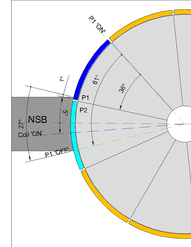
        To demonstrate the point of disagreement between us on the issue of timing, I present the 10 pole 4 stator commutator / brush angles for everyones consideration.

        The method I prefer is to consider the 'time on brush' for one comm segment from 1° 'ON' to 0° 'OFF'.

        For a single coil as we have been discussing in the recent past I would estimate it as so :

        A = 'ON' angle
        B = The angle of the comm segment
        C = The angle of the brush
        D = 'OFF' angle
        E = The angle between P1 and P2 coil bisectors
        The NSB and SSB stator bisectors are 90°

        Where B + C = 'Time on brush'

        Such that the 'OFF' angle of your proposed design (which must be a positive number variable around 20°) is -

        90 - A - B - C = D

        Crudely stating the comm segment as 36° and the brush as 27° and given an 'ON' angle of 8°, then

        90 - 8 - 36 - 27 = 19°

        More accurately from the image

        90 - 8 - 61 = 21° (B + C = 61°)


        To estimate the 'OFF' angle by reference to P1 and P2 together for single coils :

        90 - A - C - E = D

        Once again, to crudely estimate

        90 - 8 - 27 - 36 = 19°

        And with more accuracy

        90 - 8 - 25* - 36 = 21° (* The brush angle is reduced to account for the comm segment gap of 1° plus 1° connection)

        ---S---

        Whilst you have not enlightened anyone on how to estimate the 'OFF' angle when designing your motor, you have demonstrated the result of considering it at the design stage, below.

        [IMG][/IMG]

        [IMG][/IMG]
        [/QUOTE]

        To calculate the advancement of the 'magnetic interaction angle' (coloured blue) toward the SSB, then

        90° (Stator bisector) - 8° (ON angle) - 21° (OFF angle) - 36° (coil bisectors or MIA) = 25° (being the angle of the brush reduced by the comm segment of 1° plus 1° connection)

        ---S---

        It's difficult to see the difference between one method and the other on account of there being NO difference...BUT...the difference is sufficiently large not to admit that there is ANY agreement at all.

        ---S---

        [IMG][/IMG]

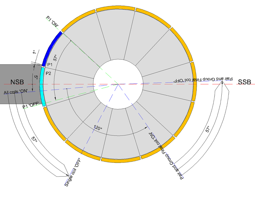
        To extend my 'flawed' method of estimation (notwithstanding the same outcome, just luck I suppose) to the 12 pole 4 pole pairs wind -

        A = 'ON' angle
        B = The angle of the comm segment
        C = The angle of the brush
        D = 'OFF' angle
        F = The angle between P1 Coil 1 and P1 Coil 2 bisectors
        The NSB and SSB stator bisectors are 180°

        180 - A - B - C - F = D

        Crudely

        180 - 5 - 30 - 30 - 120 = -5°

        More accurately

        180 - 5 - 57 - 120 = -2°

        The negative number denotes the coils remained energised past the SSB when they should disengage prior to the SSB.

        Hopefully that clears up any confusion on why we don't agree.


        Happy Hunting

        mark

        Comment


        • Originally posted by Ufopolitics View Post
          Have anyone here- including You- done ANYONE of those two simple tests?
          Firstly. It never even occurred to me that I should. For the motor speeds that I've been encountering and the fact they do not 'sit' locked onto the RPM, I have never thought that was even measurable. Trying some lower voltage tests might be sufficiently illuminating for me to try. And thank you for suggesting it.

          Secondly. I shall re read your post to fully digest the information.

          My thoughts on these motors and how they behave between connection has changed in the last few days. Your Imperial diagram, when it is motoring on all 4 gates must be firing north on the north magnet and south on the south magnet to rotate by repulsion. I'm going to pay my mind to this and what implications it has for my current interest in the single comm hybrid design.

          Delightedly Hunting

          mark

          Comment


          • Question on this calculation

            Originally posted by HuntingRoss View Post

            To extend my 'flawed' method of estimation (notwithstanding the same outcome, just luck I suppose) to the 12 pole 4 pole pairs wind -

            A = 'ON' angle
            B = The angle of the comm segment
            C = The angle of the brush
            D = 'OFF' angle
            F = The angle between P1 Coil 1 and P1 Coil 2 bisectors
            The NSB and SSB stator bisectors are 180°

            180 - A - B - C - F = D

            Crudely

            180 - 5 - 30 - 30 - 120 = -5°

            More accurately

            180 - 5 - 57 - 120 = -2°

            The negative number denotes the coils remained energised past the SSB when they should disengage prior to the SSB.

            Hopefully that clears up any confusion on why we don't agree.


            Happy Hunting

            mark
            So Mark, I don't think I see the above calculation highlighted in purple applying to the dual coil group for the 12 pole, done for the 10 pole. I know it only has the single coil. But I guess this type of calculation can prove that a coil will not be improperly energized past the top dead center of any magnet sector bisector. I think I can make the substitutions to get that calculation, but just thought I'd ask for now... I guess the 4-pole coil doesn't have this problem you show for the 12-pole?

            Sam
            Up, Up and Away

            Comment


            • First: Reviewing Previous Discussion

              @Mark Ross,

              Ok, Mark...I also want to reach an agreement here, believe me...for the sake of all members attending this Thread, and, of course, mainly to the ones actively replicating this Machines.

              As...in the end everyone will get benefit out of our final conclusion.

              What am doing on this Post is reviewing our initial arguments related to Timing...and I will be just showing the essential parts of concern, since there is a LOT of text involved from both of Us.


              Originally posted by HuntingRoss View Post
              Excellent graphics as always UFO which paint the picture perfectly...AND...we agree, it seems.

              [IMG][/IMG]

              I didn't want to go into fractions of degrees when broad principles establishes the point, but I can.

              I referred to 'pole angles' as 'A' being 1/28 of 360°...which is 12.857°
              The angle between P1C2 and P2C1, I referred to this as 'Z' being '5A' ...which is 64.285°
              I notice you have indicated the brush width as being approximately 50% of the comm segment width, not full width as it is in my 12 pole motor. This reduces the sweep angle 'sA' before P2 disconnects from 12.857° to...6.428°
              Ok, Mark up to here you were doing the Wrong Calculations for the Brush Sweep Angle (sA) ...look above and then below:

              When comparing your previous above calculations to our latest conclusions, starting at My "Five Frames Film Strip Diagram"...We both agreed that the Total Sweep Angle or ON Angle is equal to: Commutator Segment Angle PLUS Brush Angle.

              You obviously were deducting instead of adding both angles...

              But, the CENTER and MAIN Discussion STARTS below:

              Originally posted by HuntingRoss View Post
              ...So

              X + Z + sA + Y = 7A = 90°

              Substituting

              X + 64.285° + 6.428° + Y = 90°
              X + Y = 19.287°

              X is tunable in the region of 5° from previous posts AND
              Y wants to be in the region of 20°

              Which adds to more than 19.287°

              Of course for the 12 pole 2 stator motor X and Y can not squeeze up to accommodate -

              'Z' being '5A' being 5/12 of 360° ...which is 150°
              The brush width being the comm width 'sA'...which is 30°

              So

              X + Z + sA + Y = 180°

              Substituting

              X + 150° + 30° + Y = 180°
              X + Y = 0°

              And therefore is not achievable.
              Ok, On your above Formulas You were ADDING sA (even the wrong total ON Angle Calculation...but the point is here you were ADDING Sweep Angle to Magnetic Interaction Angle (MIA)...


              Originally posted by Ufopolitics View Post
              Mark,

              [...]

              I am glad We agree up to a certain point, which is 360/28=12.857...as well as Five (5) Total Poles from start repulse bisector PIC2 to P2C1 create a 64.85º Angle. But let´s be even simpler here, so let´s round up 64.85 to exactly 65º

              That is all I need friend...no more angles within rotor nor commutator...but NOW, let's go from North Stator Bisector to South Stator Bisector...and we have exactly 90º.

              Now let's 'fit' 65.0º of Rotor Interaction Angle within 90º of Stators...from N1 to S1 Stator (which is only Half of Total Rotor Interaction, remember this is a Four(4) Stator)

              We set P2C1 Bisector away by 5º (towards rotation) related to North Stator Bisector , meaning we are now at 70º...and now...just the simplest math on this world...

              How much is 90º-70º=?

              Yes, exactly that... 20º, that's how far we are from South Stator Bisector.

              We have 20º to play from either side of both stator's bisectors (which is 90º)
              Up to above point I am agreeing with You...great, BUT then I tried to rectify your error about adding Switch Angle to MIA:

              Originally posted by Ufopolitics View Post
              You can NOT add EVEN 1º MORE TO 64.85º or even rounding to 65º, that is the Rotor MAX Interaction Angle based on Two Pairs being fired at same timing, when it is just one Pair being fired this Angle REDUCES TO Approx. 52º (4 Poles from Bisector to Bisector on One Pair =12.85º X 4= 52º)

              I really have absolutely NO IDEA WHY...You have to "KEEP ADDING" Commutators and Brushes angles to 65º from MAX EXTERIOR INTERACTION ANGLES, IF all those Commutator/Brushes Angles are COMPLETELY RELATIVE, as COMPLETELY IRRELEVANT TO MAGNETIC INTERACTIONS!!??


              The wires from Pair Coils to be attached to Commutator Elements-Brushes...I could flex, pull, stretch, Turn them left or right...up or down and connect them wherever I please to do...within interacting angles, or away by 10, 20, 50 100 degrees...it DOES NOT MATTER...that is just an ON-OFF Switching...as a matter of fact one could be in Japan, while the other one in Ireland...don´t care....or be Remote Control by all means...it does NOT ADD NOR SUBTRACT to the REAL MAGNETIC INTERACTIONS taking place.

              So, above was shown the "essence" of our main arguments...which is to ADD Switch Angle, or Comm. Segment PLUS Brush Angle to Magnetic Interaction Angle...

              Are we agreeing so far?

              Ok, let's end here "the Past" and go into "the Present"...your Latest Post next


              To be Continued...


              Ufopolitics
              Last edited by Ufopolitics; 05-28-2015, 02:10 PM.
              Principles for the Development of a Complete Mind: Study the science of art. Study the art of science. Develop your senses- especially learn how to see. Realize that everything connects to everything else.― Leonardo da Vinci

              Comment


              • Originally posted by HuntingRoss View Post
                Sometimes I write 'assume' or 'presume' to sound less emphatic, but really on this subject I have no doubt.

                [img][/img]

                To demonstrate the point of disagreement between us on the issue of timing, I present the 10 pole 4 stator commutator / brush angles for everyones consideration.
                Ok, Great!, it is Sam-po-Joe's Special Beauty!...

                The method I prefer is to consider the 'time on brush' for one comm segment from 1° 'ON' to 0° 'OFF'.
                Sounds good so far...

                For a single coil as we have been discussing in the recent past I would estimate it as so :

                A = 'ON' angle
                B = The angle of the comm segment
                C = The angle of the brush
                D = 'OFF' angle
                E = The angle between P1 and P2 coil bisectors
                The NSB and SSB stator bisectors are 90°
                Up to here I understand all codes written above...I guess you wrote P1-P2 as a Typo...since we are on Single Coils (underlined).

                Plus, it would help if you assign a Letter to Stators Bisector Angle.

                Where B + C = 'Time on brush'
                Ok, Mark, here we are both in agreement as to ADD comm. Segment Angle to Brush Angle...or a "Sweep Angle" (sA) from previous post right?

                Such that the 'OFF' angle of your proposed design (which must be a positive number variable around 20°) is -

                90 - A - B - C = D

                Crudely stating the comm segment as 36° and the brush as 27° and given an 'ON' angle of 8°, then

                90 - 8 - 36 - 27 = 19°

                More accurately from the image

                90 - 8 - 61 = 21° (B + C = 61°)

                To estimate the 'OFF' angle by reference to P1 and P2 together for single coils :

                90 - A - C - E = D

                Once again, to crudely estimate

                90 - 8 - 27 - 36 = 19°

                And with more accuracy

                90 - 8 - 25* - 36 = 21° (* The brush angle is reduced to account for the comm segment gap of 1° plus 1° connection)

                ---S---
                Yes Mark...of course You have it right this time...since you are Not Adding BUT Subtracting the Switch ON Time on ALL your above equations.


                Whilst you have not enlightened anyone on how to estimate the 'OFF' angle when designing your motor...
                Of course I couldn't "enlighten" anyone, just because you did not allow me to...with all your continuous arguments INSISTING ON keep ADDING the switch Angle to the Interaction Angles!

                you have demonstrated the result of considering it at the design stage, below.

                [IMG][/IMG]

                [IMG][/IMG]

                To calculate the advancement of the 'magnetic interaction angle' (coloured blue) toward the SSB, then

                90° (Stator bisector) - 8° (ON angle) - 21° (OFF angle) - 36° (coil bisectors or MIA) = 25° (being the angle of the brush reduced by the comm segment of 1° plus 1° connection)

                ---S---

                It's difficult to see the difference between one method and the other on account of there being NO difference...BUT...the difference is sufficiently large not to admit that there is ANY agreement at all.

                ---S---
                Mark,

                Of course We don't have any difference NOW!!...since you have rectified your mistake...and started SUBTRACTING instead of ADDING the ON Switching Time.

                Still, You have "divided" your Equations in Two Parts...and I don't understand why?...what is the point on doing so?

                First You subtracted ONLY Switching Angles, meaning A,B,C & D to Stators Bisectors Angle (90º)...

                Then you mixed...

                90 - A - C - E = D

                or...

                90 - 8 - 27 - 36 = 19°

                Where E is the MIA, C is Brush Angle...and A is the ON Angle or Repulse Angle.

                Now, there is one "special" issue (I will better call it "Unique") in Sampojo's 10 Pole/4 Stators and 4 Pole Single Coils:

                In that motor the Magnetic Interaction Angle (MIA) is exactly identical to the Commutator Segment Angle...Both being 36º...which is a very rare "Relation" to find in any other Four Stator Motor.

                Meaning E=B


                It tends to certain confusion when we add or subtract the number "36º" in any of above equations, no matter what letter is assigned...since the results would be the same. So in both equations is understood the results are the same.

                NOW LET'S VERIFY IF YOUR EQUATIONS ABOVE HOLD TRUE IN A CONVENTIONAL MOTOR:

                So let's choose Imperial, since it is a Four Stator as well, except E is not equal to B

                [IMG][/IMG]

                So We have Pairs P1 and P2 each engaging Four Poles:

                A = 'ON' angle=
                B = The angle of the comm segment = Here we use Two Segments, cause they are 56 total, each Two is then @ 12.85º round to 13º
                C = The angle of the brush= 13º
                D = 'OFF' angle = ?
                E = The angle between P1 and P2 coil bisectors = 64.85º = Let´s round it to 65º
                F=The NSB and SSB stator bisectors are 90°

                Let's "clean" all this below:

                A=5º
                B=13º
                C=13º
                D= ?
                E= 65º
                F= 90º

                So let's calculate D , and we all know D= 90-5-65 which is exactly 20º...

                According to Mark's Equation:

                D= 90 - A - C - E

                D= 90- 5 - 13 - 65

                D= 7

                So, unfortunately finding D don't work on your above Equation Mark.

                Now let's use your other Formula...:

                90 - A - B - C = D

                D= 90-5-13-13

                D= 59


                Close, but Nope...it can not be applied to a "Conventional" Motor Mark...so we can not use it as a "Universal Applicable Equation" am really sorry...just because We will have to keep "Hunting"...


                Hopefully that clears up any confusion on why we don't agree.


                Happy Hunting

                mark

                Even though the negative results trying to calculate Imperial...I am still happy you are not adding switching angles...but deducting them...which I consider a step forward in our Timing Calculating Process.


                Keep Hunting (hopefully very happy...)


                Ufopolitics
                Last edited by Ufopolitics; 05-28-2015, 05:34 PM.
                Principles for the Development of a Complete Mind: Study the science of art. Study the art of science. Develop your senses- especially learn how to see. Realize that everything connects to everything else.― Leonardo da Vinci

                Comment


                • Originally posted by HuntingRoss View Post
                  To extend my 'flawed' method of estimation (notwithstanding the same outcome, just luck I suppose) to the 12 pole 4 pole pairs wind -

                  A = 'ON' angle
                  B = The angle of the comm segment
                  C = The angle of the brush
                  D = 'OFF' angle
                  F = The angle between P1 Coil 1 and P1 Coil 2 bisectors
                  The NSB and SSB stator bisectors are 180°

                  180 - A - B - C - F = D

                  Crudely

                  180 - 5 - 30 - 30 - 120 = -5°

                  More accurately

                  180 - 5 - 57 - 120 = -2°

                  The negative number denotes the coils remained energised past the SSB when they should disengage prior to the SSB.
                  [IMG][/IMG]

                  @ UFO

                  Unfortunately you used the equation for a single coil to estimate the Imperial Pairs wind...and you took the brush angle as 13° when it is half that 6.5°

                  You also said the answer derived from the equation was wrong without saying why or what it should be.

                  Plugging in the angles for Pairs, P1 interaction only -

                  A = 5
                  B = 12.85
                  C = 6.43 (12.85 / 2)
                  D = ?
                  F = 51.4 (12.85 x 4)
                  NSB to SSB = 90

                  90 - 5 - 12.85 - 6.42 - 51.4 = 14.33°

                  ---S---

                  And to calculate the 'OFF' angle for Pairs, P1 and P2 combined interaction -

                  G = The angle between P1 Coil 1 and P2 Coil 2 = 64.25 (12.85 x 5)

                  90 - A - C - G = D

                  90 - 5 - 6.42 - 64.25 = 14.33°

                  ---S---

                  So the coils are off before they approach the SSB. The designer has to make a value judgment on whether that is too close (or not) to the SSB.

                  Exuberantly Hunting

                  mark

                  Comment


                  • Originally posted by HuntingRoss View Post
                    [IMG][/IMG]

                    @ UFO

                    Unfortunately you used the equation for a single coil to estimate the Imperial Pairs wind...
                    Mark,

                    So, Now We should use a "specific" equation for "Single Coils" and another one for Pairs?...come on, man...are you real?

                    This is extremely funny now!

                    Why so?

                    We have exactly same parameters same angles, same Two Bisectors dictating the Magnetic Interaction Angle??

                    and you took the brush angle as 13° when it is half that 6.5°
                    Mark, now are you gonna tell me what the Imperial(S) seating at my bench measurements are?

                    Those are REAL Measurements Mark.

                    Forget what the diagram looks like...am giving the REAL VALUES ABOVE.

                    You also said the answer derived from the equation was wrong without saying why or what it should be.
                    You are not reading well and slow enough Mark, it is there...It is as well on Diagram

                    D MUST BE around 20º

                    Everything below are the wrong measurements, therefore wrong results


                    Plugging in the angles for Pairs, P1 interaction only -

                    A = 5
                    B = 12.85
                    C = 6.43 (12.85 / 2)
                    D = ?
                    F = 51.4 (12.85 x 4)
                    NSB to SSB = 90

                    90 - 5 - 12.85 - 6.42 - 51.4 = 14.33°

                    ---S---

                    And to calculate the 'OFF' angle for Pairs, P1 and P2 combined interaction -

                    G = The angle between P1 Coil 1 and P2 Coil 2 = 64.25 (12.85 x 5)

                    90 - A - C - G = D

                    90 - 5 - 6.42 - 64.25 = 14.33°

                    ---S---

                    So the coils are off before they approach the SSB. The designer has to make a value judgment on whether that is too close (or not) to the SSB.

                    Exuberantly Hunting

                    mark

                    THERE MUST BE JUST ONE EQUATION THAT FITS ALL MOTORS, NO MATTER IF TWO STATORS, FOUR STATORS AND NO MATTER IF FOUR OR TWO BRUSHES.

                    That is the perfect Equation Guy!

                    Now you are "pulling out of your sleeve a "G" Parameter?

                    What is the difference between "F" and "G" ?...Both are based two guiding/dictating bisectors...

                    Get your numbers set together and well Mark...


                    Look at your calculation for your 12 pole 4 Pole Coils in the Pair...you have F=120º....when it is 150º

                    5X30=150º


                    Ufopolitics
                    Last edited by Ufopolitics; 05-28-2015, 10:41 PM.
                    Principles for the Development of a Complete Mind: Study the science of art. Study the art of science. Develop your senses- especially learn how to see. Realize that everything connects to everything else.― Leonardo da Vinci

                    Comment


                    • Originally posted by sampojo View Post
                      So Mark, I don't think I see the above calculation highlighted in purple applying to the dual coil group for the 12 pole, done for the 10 pole. I know it only has the single coil. But I guess this type of calculation can prove that a coil will not be improperly energized past the top dead center of any magnet sector bisector. I think I can make the substitutions to get that calculation, but just thought I'd ask for now... I guess the 4-pole coil doesn't have this problem you show for the 12-pole?

                      Sam
                      Hi Sam

                      The equations you quoted from a section of my post are for PAIRS only so you're correct, it will not apply to your single coil wind.

                      For a single coil wind you should use the following -

                      Originally posted by HuntingRoss View Post
                      I present the 10 pole 4 stator commutator / brush angles for everyones consideration.

                      The method I prefer is to consider the 'time on brush' for one comm segment from 1° 'ON' to 0° 'OFF'.

                      For a single coil as we have been discussing in the recent past I would estimate it as so :

                      A = 'ON' angle
                      B = The angle of the comm segment
                      C = The angle of the brush
                      D = 'OFF' angle
                      E = The angle between P1 and P2 coil bisectors
                      The NSB and SSB stator bisectors are 90°

                      Where B + C = 'Time on brush'

                      Such that the 'OFF' angle of your proposed design (which must be a positive number variable around 20°) is -

                      Considering P1 interaction only

                      90 - A - B - C = D

                      Crudely stating the comm segment as 36° and the brush as 27° and given an 'ON' angle of 8°, then

                      90 - 8 - 36 - 27 = 19°

                      More accurately from the image

                      90 - 8 - 61 = 21° (B + C = 61°)


                      To estimate the 'OFF' angle by reference to P1 and P2 combined together for single coils :

                      90 - A - C - E = D

                      Once again, to crudely estimate

                      90 - 8 - 27 - 36 = 19°

                      And with more accuracy

                      90 - 8 - 25* - 36 = 21° (* The brush angle is reduced to account for the comm segment gap of 1° plus 1° connection)
                      For Groups the equation for P1 interaction only would be, where
                      F = The angle between the first and last coil bisectors and
                      G = The angle between the NSB and SSB

                      G - A - B - C - F = D


                      Happy Hunting

                      mark[/QUOTE]

                      Comment


                      • Originally posted by Ufopolitics View Post
                        So, Now We should use a "specific" equation for "Single Coils" and another one for Pairs?...come on, man...are you real?

                        This is extremely funny now!

                        Why so?
                        If we consider only the P1 interaction (my preferred option) then a single coil has one bisector which advances towards the SSB described by the addition of Comm + Brush angle.

                        If we consider only the P1 interaction for a Pair or Group wind the final coil bisector is closer to the SSB before we consider the amount it advances from Comm + Brush. Hence the angle between the first and last coil is added to the equation.

                        It's all been described in words and drawing.


                        Originally posted by Ufopolitics View Post
                        Mark, now are you gonna tell me what the Imperial(S) seating at my bench measurements are?
                        I thought it was a typo which is why I corrected it. Without looking for the #post on the subject, from memory you remarked the Imperial brush is the width of one of the 56 comm segments and two segments are tied together...From memory.

                        Originally posted by Ufopolitics View Post
                        D MUST BE around 20º
                        I know it must be around 20º. What I'm trying to ascertain from a crude method of measurement is what it really is.

                        Why not just tell me (all of us) how you would work it out ?

                        Originally posted by Ufopolitics View Post
                        THERE MUST BE JUST ONE EQUATION THAT FITS ALL MOTORS, NO MATTER IF TWO STATORS, FOUR STATORS AND NO MATTER IF FOUR OR TWO BRUSHES.
                        It's not simply a function of stators or brushes. The Pairs and Groups 'reach out' to the SSB...in effect bringing it closer. It stands to reason that if the final bisector is wound further towards the SSB without considering the 'time on brush', then the final bisector can reach the SSB whilst still energised. If the final bisector was 30º from the SSB when its comm segment has just connected and it had 30º to travel before disconnecting...Then we have a problem with the design.

                        Originally posted by Ufopolitics View Post
                        Look at your calculation for your 12 pole 4 Pole Coils in the Pair...you have F=120º....when it is 150º

                        5X30=150º
                        The angle between P1 Coil 1 and P1 Coil 2 is 120º.
                        The angle between P1 Coil 1 and P2 Coil 2 is 150º.

                        Still Happily Hunting

                        mark

                        Comment


                        • Originally posted by HuntingRoss View Post
                          If we consider only the P1 interaction (my preferred option) then a single coil has one bisector which advances towards the SSB described by the addition of Comm + Brush angle.
                          You can NOT just "decide" (because is your "preferred" option) to IGNORE the ENDING INDEPENDENT CIRCUIT BEING ENERGIZED IN DUE CYCLE(and I write "Circuit" as a General Term, because it Includes ALL Type of Coils, Single, Pairs or Groups)

                          The Ending Circuit is required at all times (IN ALL TYPE OF WINDINGS) because this is ALL about A SEQUENTIAL-ROTATIONAL ORDER that takes place in Time and Space during OPERATION.

                          Remember this are ALL ROTARY MACHINES....so what goes around...comes around...

                          If it is about Single Coils, You MUST include in the Calculations C1 AND C2, because they DO get connected SIMULTANEOUSLY in this type of Motors in a 50% of TIME-SPACE AT EACH 360º TURN for Two Stators...AND TWICE in 360º Turn for Four Stators during Machine Operation.


                          If we consider only the P1 interaction for a Pair or Group wind the final coil bisector is closer to the SSB before we consider the amount it advances from Comm + Brush. Hence the angle between the first and last coil is added to the equation.

                          It's all been described in words and drawing.
                          It is the completely wrong method, not to consider BOTH CIRCUITS in an Equation to Calculate proper Interactions.

                          Actually, C2, P2 or G2 are the FINAL DICTATING Coils that tell Us, IF or NOT We are correct before proceeding to wind THE ROTOR, in ANY KIND of Winding Displayed on this Thread.

                          Simply ignoring this FACT above, will lead in the construction of a completely unusable Machine, that would never perform as expected.

                          Sounds familiar Mark?

                          I thought it was a typo which is why I corrected it. Without looking for the #post on the subject, from memory you remarked the Imperial brush is the width of one of the 56 comm segments and two segments are tied together...From memory.
                          Your Memory is failing to recall that I corrected that fact in a previous post here.

                          Imperial Commutator is based on 56 segments and 28 Rotor Poles. The Brush Angle in Imperial is equal to Two Segments Angle.

                          Since the first Imperial here was ever wound, We used two commutator segments bridged to one circuit. This way is a 1:1 Switch Ratio.

                          I know it must be around 20º. What I'm trying to ascertain from a crude method of measurement is what it really is.
                          So, Mark...Now that you have all the Right and Real Measurements from Imperial ...Go ahead, use your correct equation now..the one specifically designed for Pairs ...and see if it even comes up close to 20º..

                          Why not just tell me (all of us) how you would work it out ?
                          The Process is simple, so simple that without any formulas or equations, anyone seating in front of ANY Motor IN A REAL BUILD, could work it out very easy.

                          Just go through all the Members on this Thread that have done very successful asymmetric machines of many different structures without any previous existing "formulas".

                          Just look at Richard Bates (Midaz)...This guy obviously have no access to any CAD Software, besides he has no idea how to even start drawing a circle without the assistance of a round cup...He tries to avoid any conversation involving Math or Geometry Calculations ...However, He has built an Imperial in two windings methods by now...and they work...He even came up with his own idea...poor idea, but he made it run.

                          I will do put together the Right Equation...in time.

                          But first, I want to erase from everyone's mind here all the Confusion You have created and spread with your wrong assumptions, your wrong preferred methods and presumptions... mixing switching angles with magnetic interactions back and forth.

                          It's not simply a function of stators or brushes.
                          Oh, they are simple functions!...is just about to define a way to see them all in easier planes...for example...just by taking all this Angular Rotations into linear graphics movements simplifies this process even more. Rotations tend to confusions, basically not being able to distinguish between a smaller wheel like a Commutator, within a larger wheel of a Rotor, even though BOTH having the same exact, identical angles, and taking place within the same Time and Space...having both RADICAL traveling Distances differences...I know You are one who can not distinguish this fact properly.

                          The Pairs and Groups 'reach out' to the SSB...in effect bringing it closer. It stands to reason that if the final bisector is wound further towards the SSB without considering the 'time on brush', then the final bisector can reach the SSB whilst still energised. If the final bisector was 30º from the SSB when its comm segment has just connected and it had 30º to travel before disconnecting...Then we have a problem with the design.
                          Right Mark, and that "final bisector" underlined in your statement above three (3) times, is the one that dictates if or not your design will work out successfully...And that "final bisector" is defined in a 50% of whole rotation by the C2, P2 and G2 Circuits...which, according to your "preference" you ignore in your equations...meaning..."standing out of your reason"...


                          The angle between P1 Coil 1 and P1 Coil 2 is 120º.
                          The angle between P1 Coil 1 and P2 Coil 2 is 150º.

                          Still Happily Hunting

                          mark
                          There you are!...You only consider for your "specific designed formula" applicable to "Pairs Only"..."F" as The angle between P1 Coil 1 and P1 Coil 2 is 120º...Ignoring P2 "final bisector" from Coil 2 as you have written above, just because the one who dictates the 50 percent possibility of error by a 30º Margin Angle is that "final bisector"...and that is a BIG TIME ERROR guy!...Basically in such small sized rotor number of poles like the only ones you have worked on...the 12 poles.

                          I thought it was a "typo"...now you confirmed your serious mistake.

                          The more you write here...the more convinced I am as of why all your 'beasts' never performed as expected, completely opposite results to hundreds of successful replications that have being taking place for over two years on this Thread.


                          Keep hunting...but be aware of many targets out there which are not an easy piece to shut down...


                          Ufopolitics
                          Last edited by Ufopolitics; 05-29-2015, 03:08 PM.
                          Principles for the Development of a Complete Mind: Study the science of art. Study the art of science. Develop your senses- especially learn how to see. Realize that everything connects to everything else.― Leonardo da Vinci

                          Comment


                          • I shall revise the figures for the Imperial Pairs in RED below. Correcting the single comm width brush to 2 comm width as advised by UFO.

                            Originally posted by HuntingRoss View Post
                            [IMG][/IMG]


                            Plugging in the angles for Pairs, P1 interaction only -

                            A = 5
                            B = 12.85
                            C = 12.85
                            D = ?
                            F = 51.4 (12.85 x 4)
                            NSB to SSB = 90

                            90 - 5 - 12.85 - 12.85 - 51.4 = 7.9°

                            ---S---

                            And to calculate the 'OFF' angle for Pairs, P1 and P2 combined interaction -

                            G = The angle between P1 Coil 1 and P2 Coil 2 = 64.25 (12.85 x 5)

                            90 - A - C - G = D

                            90 - 5 - 12.85 - 64.25 = 7.9°

                            Originally posted by Ufopolitics View Post
                            You can NOT just "decide" (because is your "preferred" option) to IGNORE the ENDING INDEPENDENT CIRCUIT BEING ENERGIZED IN DUE CYCLE
                            I can. Because ???...I accounted for it in the two different formula. 'G' is larger than 'F' by 12.85°. Because ???...P2 is ONE pole advanced from P1.

                            P2 is just a snapshot of P1 in the future...P1 will adopt that position in 12.85° time.

                            P1 is on the brush for probably 2° less than 25.7°. That's 1° gap plus 1° connection. But I shall ignore the detail for the purpose of illustration.

                            Every P from 1 to 28 is on the brush for 25.7°.

                            If P1 is on the brush by 1° it has 24.7° until disconnection. P2 has been on the brush for 13.85° and has 11.85° until disconnection.


                            Originally posted by Ufopolitics View Post
                            It is the completely wrong method, not to consider BOTH CIRCUITS in an Equation to Calculate proper Interactions.
                            When you account for the total 'time on brush' for one comm segment it works just fine...every time.


                            Originally posted by Ufopolitics View Post
                            So, Mark...Now that you have all the Right and Real Measurements from Imperial ...Go ahead, use your correct equation now..the one specifically designed for Pairs ...and see if it even comes up close to 20º.
                            I have to say, I don't like the look of 7.9° as the 'OFF' angle. But it probably works OK.


                            Originally posted by Ufopolitics View Post
                            The Process is simple, so simple that without any formulas or equations, anyone seating in front of ANY Motor IN A REAL BUILD, could work it out very easy.
                            I know. I just look at the final bisector and count on two poles and see if this looks good or not...it takes a second to do.


                            Originally posted by Ufopolitics View Post
                            I will do put together the Right Equation...in time.
                            You're correct. There is one equation that fits all motors. But it will have some variables in it. So far it has been simple addition or subtraction.


                            Originally posted by Ufopolitics View Post
                            ...and that "final bisector" underlined in your statement above three (3) times, is the one that dictates if or not your design will work out successfully...
                            Correct.


                            Originally posted by Ufopolitics View Post
                            ...which, according to your "preference" you ignore in your equations...
                            Incorrect.
                            Accounted for in both formula.


                            Originally posted by Ufopolitics View Post
                            There you are!...You only consider for your "specific designed formula" applicable to "Pairs Only"..."F" as The angle between P1 Coil 1 and P1 Coil 2 is 120º...Ignoring P2 "final bisector" from Coil 2 as you have written above, just because the one who dictates the 50 percent possibility of error by a 30º Margin Angle is that "final bisector"...and that is a BIG TIME ERROR guy!...
                            Incorrect.
                            For P1 just connecting and 120º (crudely) it has 60º on the brush.
                            For P1 just connecting and 150º (crudely) P2 has just 30º left on the brush.
                            See. Accounted for.


                            Originally posted by Ufopolitics View Post
                            ...but be aware of many targets out there which are not an easy piece to shut down...
                            What does that even mean.

                            Like I have said before. The 4 pole pairs wind seems to be problematic because it just spans across too many poles between the magnet bisectors.


                            Deliriously Happy Hunting

                            mark

                            Comment


                            • Found it.

                              Originally posted by Midaztouch View Post
                              The brushes on the Imperial are the width of 2 commutator segments... Not 1 comm segment.
                              A lot of Hunting

                              mark

                              Comment


                              • Originally posted by Ufopolitics View Post
                                The Process is simple, so simple that without any formulas or equations, anyone seating in front of ANY Motor IN A REAL BUILD, could work it out very easy.

                                Originally posted by HuntingRoss View Post
                                I know. I just look at the final bisector and count on two poles and see if this looks good or not...it takes a second to do.
                                This quote above we can absolutely agree on.

                                Chances are that the motor you're working with has a brush the same size as the comm segments.

                                When you're drafting your schematic, look at where P1 is just connecting then count two poles on from your last coil bisector to estimate your 'OFF' angle. If you're designing a single coil motor then the coil bisector 'is' your last bisector and so the same principle applies.

                                It really is that simple.

                                For motors where the brush is narrower than the comm segments, the final coil bisector will advance less than two poles.

                                Good Hunting

                                mark

                                Comment

                                Working...
                                X