 Tweet
Tweet
goldmine wire lengths
@Sampojo
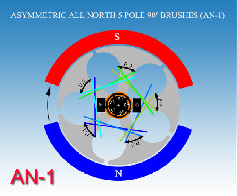
The goldmine motors that I wound were with AWG30 18'6'' for total length which results in 2.5 ohms resistance. When I wound the AN1, I measured 9'3" and put a tape marker like when winding the Y winding. Then without cutting the wire measured another 9'3" for the second coil. Sounds like an interesting project.
Cheers
Garry
@Sampojo
The goldmine motors that I wound were with AWG30 18'6'' for total length which results in 2.5 ohms resistance. When I wound the AN1, I measured 9'3" and put a tape marker like when winding the Y winding. Then without cutting the wire measured another 9'3" for the second coil. Sounds like an interesting project.
Cheers
Garry


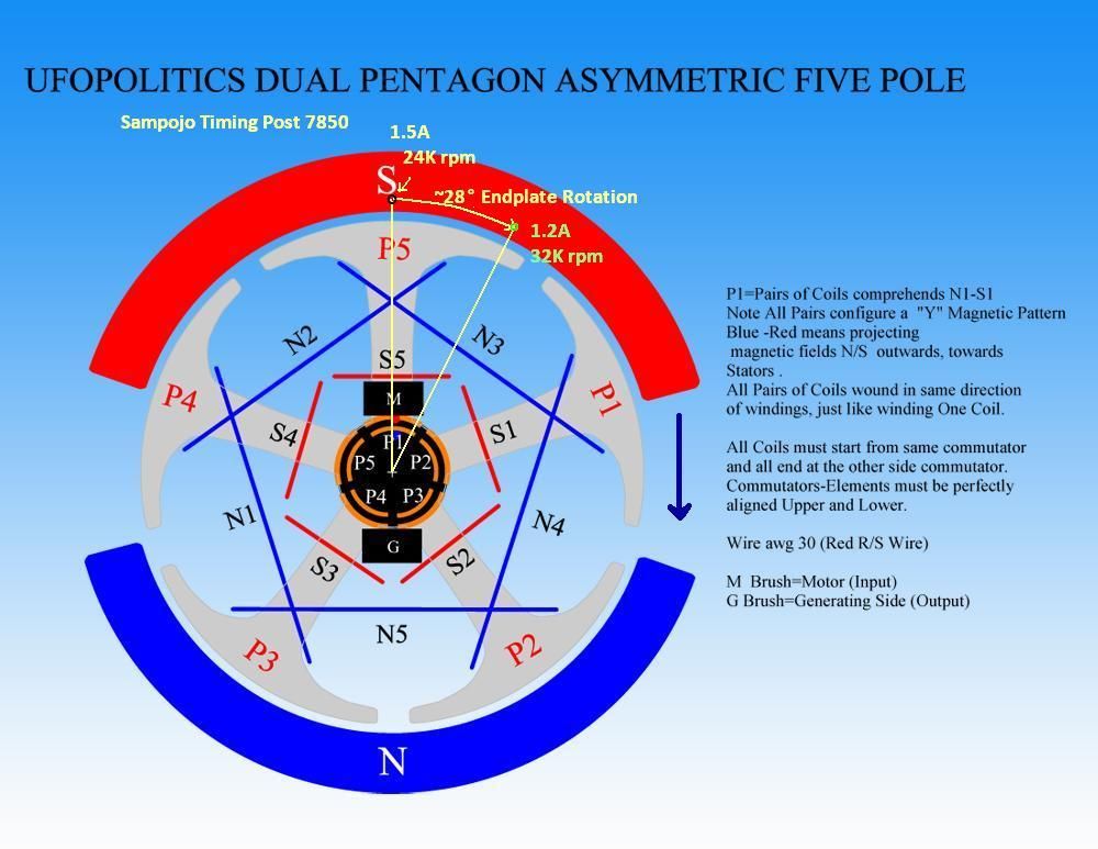


 . I estimate that I was moving the endplates 6-12 deg per adjustment. A nice old-fashioned panel and meter would be better to take amperage data then a digital VOM, judging by the way it fluctuates.

Comment