 Tweet
Tweet
Originally posted by Ufopolitics
View Post
Hello Dave,
Something like "Gone Baby Gone"... ?
?
Yes, but in order to really "SEE WHAT IT DOES"...We need to go through the Math...unfortunately.
And I am very good at Electrical/Math, and I love it... ...and heavy Calculus ones, mmmm...this is just "a breeze" for Me...besides also Heavy Building...that includes Heavy Machinery...Mig, Tig Welding, Plasma cutting, Lathing...etc...Plus beautiful CAD and 3D Designs you have seen...and yes, it makes me feel that I am sooo good!!!...
 (just kidding, some Ego Blasting here...to burst some "envy, hate, and jealousy"...LOL...I know is not good though...So I keep beating up myself for doing it...LOL)
Now seriously...
Dave ...Sorry to tell you, but You are lost man...
Dave, Ec is C EMF...simplified as E=Energy and C=Counter
Watch again Peter Lindemann Video (And We all are gonna have to get together at some point and make some donation to Peter here...to be fair, like you have said about his Copyrights, seriously)
It is clearly stated there at Video Time: 0:27:13 and on...where
Ea=Voltage Source
Ec= C EMF
Ia=Current at Armature
Ra=Resistance of Coils + Brushes (Here if we keep it at exactly 1.0 Ohms, it multiplies without affecting other parameters.)
Therefore it is clearly Stated at: 0:31:10 the Main Formula for Armature "Power"
What actually moves the armature current through the armature coils is the difference between the voltage applied to the motor (Ea) minus the counter-emf (Ec). Thus Ea-Ec is the actual voltage effective in the armature and it is this effective voltage which determines the value of the armature current. Since generally I=E/R from Ohm's Law, in the case of the DC Motor, Ia=Ea-Ec/Ra. Also , since according to Kirchhoff's Second Law, the sum of the voltage drops around any closed circuit must equal the sum of thye applied voltages, then Ea=Ec+IaRa.
At 0:40:51 We find "Dynamometer Test Revisited", where Peter shows results and calculations after the Dyno Test to find COP, Efficiency...
Motor at Idle:
12.1 Volts 1.1 Amps 2235 RPM
Motor Under Load
12.1 Volts 7.0 Amps 1864 RPM
Input Voltage @ 1864 RPM=10 Volts
Back EMF @ 1864 RPM= 9.0 Volts
EFFECTIVE VOLTAGE RUNNING OUR MOTOR UNDER LOAD TEST:
Applied Voltage=12.1 Volts
-Back EMF Voltage= 9.0 Volts
_________________________
Effective Voltage = 3.1 Volts
Then calculating COP (Coefficient Of Performance)...
COP =
Effective Voltage (3.1 Volts)
______________________= 0.256
Applied Voltage (12.1 Volts)
SO WHAT IS THE REAL POWER DRIVING OUR MOTOR DURING OUR LOAD TEST? (Time on Video 0:43:13)
INPUT:
Effective Volts=3.1
Amps=7.0
_________________
Effective Input: Watts=21.7
(Applied Input: Watts=84.7)
Effective Input/1HP= 21.7W/746W=0.029 HP
Efficiency= Output/Input=0.087HP/0.029HP=300%
But...
REAL EFFICIENCY= 300% X 0.256 COP= 76.7 % Efficiency
Conclusion: The Back EMF Masks the excellent performance of the Motor, and hides it behind a very low COP
Something like "Gone Baby Gone"...
?Yes, but in order to really "SEE WHAT IT DOES"...We need to go through the Math...unfortunately.
And I am very good at Electrical/Math, and I love it...
...and heavy Calculus ones, mmmm...this is just "a breeze" for Me...besides also Heavy Building...that includes Heavy Machinery...Mig, Tig Welding, Plasma cutting, Lathing...etc...Plus beautiful CAD and 3D Designs you have seen...and yes, it makes me feel that I am sooo good!!!... (just kidding, some Ego Blasting here...to burst some "envy, hate, and jealousy"...LOL...I know is not good though...So I keep beating up myself for doing it...LOL)Now seriously...
Dave ...Sorry to tell you, but You are lost man...
Dave, Ec is C EMF...simplified as E=Energy and C=Counter
Watch again Peter Lindemann Video (And We all are gonna have to get together at some point and make some donation to Peter here...to be fair, like you have said about his Copyrights, seriously)
It is clearly stated there at Video Time: 0:27:13 and on...where
Ea=Voltage Source
Ec= C EMF
Ia=Current at Armature
Ra=Resistance of Coils + Brushes (Here if we keep it at exactly 1.0 Ohms, it multiplies without affecting other parameters.)
Therefore it is clearly Stated at: 0:31:10 the Main Formula for Armature "Power"
What actually moves the armature current through the armature coils is the difference between the voltage applied to the motor (Ea) minus the counter-emf (Ec). Thus Ea-Ec is the actual voltage effective in the armature and it is this effective voltage which determines the value of the armature current. Since generally I=E/R from Ohm's Law, in the case of the DC Motor, Ia=Ea-Ec/Ra. Also , since according to Kirchhoff's Second Law, the sum of the voltage drops around any closed circuit must equal the sum of thye applied voltages, then Ea=Ec+IaRa.
At 0:40:51 We find "Dynamometer Test Revisited", where Peter shows results and calculations after the Dyno Test to find COP, Efficiency...
Motor at Idle:
12.1 Volts 1.1 Amps 2235 RPM
Motor Under Load
12.1 Volts 7.0 Amps 1864 RPM
Input Voltage @ 1864 RPM=10 Volts
Back EMF @ 1864 RPM= 9.0 Volts
EFFECTIVE VOLTAGE RUNNING OUR MOTOR UNDER LOAD TEST:
Applied Voltage=12.1 Volts
-Back EMF Voltage= 9.0 Volts
_________________________
Effective Voltage = 3.1 Volts
Then calculating COP (Coefficient Of Performance)...
COP =
Effective Voltage (3.1 Volts)
______________________= 0.256
Applied Voltage (12.1 Volts)
SO WHAT IS THE REAL POWER DRIVING OUR MOTOR DURING OUR LOAD TEST? (Time on Video 0:43:13)
INPUT:
Effective Volts=3.1
Amps=7.0
_________________
Effective Input: Watts=21.7
(Applied Input: Watts=84.7)
Effective Input/1HP= 21.7W/746W=0.029 HP
Efficiency= Output/Input=0.087HP/0.029HP=300%
But...
REAL EFFICIENCY= 300% X 0.256 COP= 76.7 % Efficiency
Conclusion: The Back EMF Masks the excellent performance of the Motor, and hides it behind a very low COP
Cheers

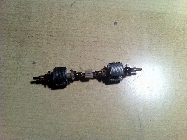
 we need the Quadradelay pulser.
 I pulled it apart and tested for a short it seemed OK but the ohms reading this time shows .4 where as when I wound it the Ohms I am sure was between .6 and .7
  It looks like I will have to pull it apart again
  even the thought of that is escaping my mind as I have tooo many things to continue with
")


 and 12-pole TORQMASTER
Comment