
tuning of the window motor
Hey Bits,
I have been experimenting with the window motor kit B and been posting on the thread : " http://www.energeticforum.com/renewa...ead.php?t=2179 "
I still havent figured the tuning of the motor completely . Have you had a chance to play around with the circuit ? If so ,
1) Any idea how to get the best torque out of the system . I have 3 full bipolar Bedidni-cole circuits that rick had provided with the kit .
2) What arrangement of coils do you recommend ? Is it like the one shown in the picture you posted or is it wrapping around the rotor as shown in potentialtec.
3) I have been wanting to build a neodymium motor myself . Is the arrangment of magnets different than what it is on Window motor kit b ( hexagon rotor( 2 inch on all sides ) with magnets ( covering the 2 inch sides completely on rotor ) . I ask this because i remember having read somewhere that the magnets cant be this close when dealing with neodymiums ...
Maybe the details of discussion are appropriate for the specific thread . But i dont know if you frequent them. So , i posted it right here when we are talking about the window motor . Will move the post with answers later to the specific thread...
Thanks for the 10 coiler demo. That is the only tutorial we have on the 10 coiler !!!
Bhargav
-
Window motor design, slots in the pipe then wrapped, only one coil. We finished wiring up this beast 4hrs before the show. We had a setback when the hub at the top gobbeld up all of the test leads that we had on it getting it running. It flung these wires all over the shop. 2 Battery banks on the back @ 36V, one bank for drive, one bank for recovery. Note the little white box under the flywheel, Tesla Switch switching technology for energizing the coil and recovery.Originally posted by Mark View PostLeave a comment:
-
Thats a different lawn mower than the one I've seen before. Is that run from a window motor design? And is that a big coil on the front inside four 90 degree drain pipes? How do you wind a coil inside it or is there a slot cut in it on the motor side? The motor only has 1 coil or are there more I cant see from the pic?Leave a comment:
-
Some Pic's of Rick's Lawn Mower, Electrical, OU, window motor driven.
Thanks
Jeff
PS Get these pic's while you can as I have to delete to make more space.Last edited by Bit's-n-Bytes; 11-17-2010, 07:22 PM.Leave a comment:
-
Here is my coil design Matt is talking about.Originally posted by Matthew Jones View Post
Thanks
JeffLast edited by Bit's-n-Bytes; 11-17-2010, 07:22 PM.Leave a comment:
-
AaronOriginally posted by Aaron View Post
I didn't have the time this morning to dig it out, but if you look through the "Use for the Tesla Switch", Jeff, Bits and Bytes to others, has circiut diagram that covers it. He talks about the benefits of it.
Somewhere above above page 95.
He may see this and post a link. I am on my way to work.
Cheers
MattLeave a comment:
-
To me the most important result of the Bedini conference seems to be that John and his associates have finally given up their reluctance to produce something other than toy sized machines. The big Ferris Wheel machine might be one way to demonstrate that substantial torque and more "out" than "in" can be had from those devices. And it definitely is the first step to having something that might one day power a house or a SUBSTANTIAL load.
Building a 30 to x coil machine with the Rick Friedrich parts and rotors is now up to the individual experimenter. Adding more rotors to the same machine, putting in generator coils and the like is just a matter of configuring the basic parts the right way.
The other big thing seems to be Bits 10 coiler running in self sustaining mode.
If this is for real-and from what I know I have no reason not to believe it- it is a proof of concept and the details in volts/amps are not that important.
I strongly recommend that you take the next step now and invite some of the most hardheaded sceptics for a test . Perhaps you could even tackle the James Randi crowd and their challenge for an overunity system or win stefan Hartmanns price at overunity . com.
Independent verification is the first step to get the mainstream interested.
Without a viable theory behind the processes this will always remain a "fringe" thing and it should not be. I am very happy that this conference was such a success. Perhaps I will be able to attend one in the future!Leave a comment:
-
Aaron,
When I first started to learn about this 2 years ago I remember reading your posts talking about the reversed winding. I figured I had to get the basics down before I started to wind your way. Your intuition is great.Leave a comment:
-
reversed winding
Who else is doing this reverse winding on the coil??? I've been showing myOriginally posted by redeagle View Post
friends this for almost 10 years! It is almost the ONLY way I ever
wind a recovery winding in my coils - the opposite direction. I have very
rarely ever wound a coil with the recovery winding going in the same direction
as the other windings.
I just learned at the end of the conference that the reverse winding was
part of the circuit??! That was exciting to hear but at the same time
very perplexing to me. Please give me a link so I can read more about this!!
Originally, it was from an intuitive understanding of what I should be doing
but found out later that it was not what was intended on a schematic.
However, I seem to get some results that others have not.
At one point, I realized I had been winding this:

Please note that the Caduceus is NOT an Aesculapius staff:
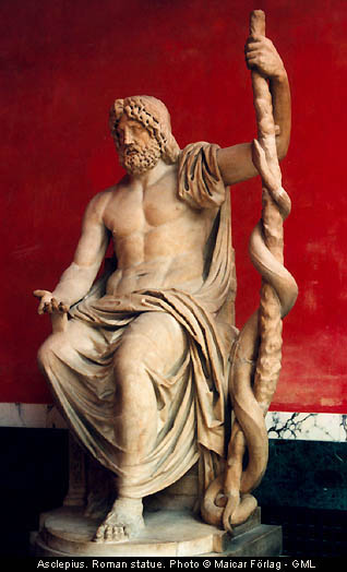
which has a single winding.
This is where I got my idea:

You see those dots in the coils?
This was before I even knew what a transistor was - to me it is a water
faucet. Input, output and the handle to let it flow, let go and it shuts off.
Anyway, those dots as I saw it meant the trigger coil and power
coil were wound so that when + was at the top of the coil north was
there. Back then, I thought that when the coil was turned off, it collapsed
and the magnetic field flipped and north was at the bottom. Hence my
thought that the dot at the bottom of the recovery winding meant north.
I thought that if I wound the coil in the opposite direction - and after
learning what Lenz's law was, I thought that if I wound the recovery
winding in the OPPOSITE direction that it would siphon off and neutralize
some of the counter efm (back emf) to the cap for more recovery and
efficiency (through a full bridge). As in siphon off some of the emf on the
applied power and then capture the spike when it collapses.
The first time was 1000 turns - power and recovery 23 awg and trigger 26
with recovery wound in opposite direction. The second time was 2000
turns of same wire types and recovery in opposite directions.
I have wound in other coils recovery windings on the core first and other
windings on top and visa versa. I usually try every permutation of a
concept like this that I can think up.
So am I finally to learn that after showing this for almost 10 years that
there actually is a difference from winding them all in the same direction
or am I missing something? If so, then it may help support my claims of
what I have experienced in many of my experiments. I don't doubt my
results but some people do. I'm not concerned about their opinions but
I would like to know if there is an "accepted" explanation of IF there is
a difference, why and what it is.
I have commented
on this reverse winding method for years but I don't think anyone was
interested in trying it out.
I am NOT saying that I want anyone to go out and do this because
it could be a waste of time and/or makes no difference. I simply invented
this method for these kinds of circuits back then based on my own
non-EE perspective on how the coils, magnetism and Lenz's law worked.
Then I found I didn't invent it... lol, go figure - nothing new under the sun.
caduceus coil - Google Search
Leave a comment:
-
electricity
I see you haven't the sense to get the punchline but in any case,Originally posted by electricity View Post
there is NO definitive definition of what electricity that can ever be proven
or agreed upon as it crosses the border between the physical world and
the unseen as a matter of indisputable fact. It is like someone trying to
prove what happens to someone when their body dies. You can think
you know what happens after that point but prove it. You can't and neither
can anyone else. Someday, it may be definitively known but today it isn't
regardless of anyone's explanation. There are just models that make more
and more sense and that is about it, in my opinion.
A dipole (battery) or any potential difference breaks the symmetry of the vacuum
flux of the positive and negative virtual photons, which I like to call the aether.
When you close the loop on a battery with a light bulb for example,
the positive potential from the vacuum moves to the positive terminal,
over the wire over the bulb and back to the negative terminal.
From the
negative terminal, the negative or anti-photon potential moves in the
opposite direction from the vacuum to the negative terminal, over the
wire and towards the positive terminal.
The electrons in the 3rd level
around the copper atoms that make up the wire are the most loosely bound
and are attracted towards the positive potential moving from the positive
terminal. The wiggle mostly up and down and move slowly like a few inches
per hour towards the positive terminal and that is the "current" or LOSS
in the system, NOT what does the work. When you measure current on
a circuit, you are NOT measuring a dissipation of energy that makes the
work, you are only measuring what happens to be lost in the process
from the circuit resistances, etc... It does not require any watts to make
a magnetic field - only the MOVEMENT OF CURRENT but not the dissipation
of it...again, any dissipation is incidental by line resistances, etc... but
that wattage is NOT what makes a magnetic field in a coil for example.
So there are those three basic flows. Positive and negative potential
flowing in opposite directions and the electrons being pulled out of orbit
by the positive charge.
When those events happen, you can say that is electricity. It does NOT
come from a "charge" in the battery. It comes from the environment
and can do so by the potential difference at the terminals causing the
local vacuum to organize and polarize instead of the vacuum potentials
normal tendency to simply be unorganized and chaotic (not random).
The photon potential moving over the wire is the Heaviside flow.
The electrons wiggling over the wire slowly towards the positive terminal
is explained basically by the "druid electron gas" model.
And this is assuming that electrons even exist - but there is NO proof
that there are electrons. We see effects, we have not seen an electron
and I don't care what they think they are observing with different novel
microscopes.
This is what electricity in my opinion, influenced by Bearden, and this is
the tip of the iceberg.
Tesla would say the aether is "electric" as an ADJECTIVE and not a noun
and that has NOTHING to do with describing electricity on a common
circuit. You said before you have to understand what electricity and
magnetism is but even more importantly, you have to understand what
energy and potential is, which are incorrectly defined in the books as
there is no such thing as a static potential that can be stored.
There is no such thing as energy. Energy is an adjective. Potential is taught
as an abstract term, but it is in fact the real "tangible" thing. When
potential moves and causes work, you describe it by using the adjective
"energy".
There is no such thing as conservation of energy as you cannot conserve
an adjective. You can conserve a potential in concept but it isn't necessary
as potential is infinite and it is pointless to try to hoard it. This isn't a
universe of poverty and no natural system conserves energy as it knows
it has unlimited potential credit that can come into the system at each
and every cycle.
You lift a ball and then all the joules of work that are required are "used
up". There is NO storage of potential in the ball at any height. A NEW
potential difference is established by its height and when it comes down,
the gravitational potential can come into play by coming into the system
to cause more work - that work is from NEW potential that came into the
system and did NOT come from what we put in to lift it. That means there
is no conservation of "energy".
It applies to springs, coils, pendulums, etc... A permanent magnet is like
a dipole and breaks the symmetry of local vacuum causing a polarized
flow of vacuum potential - the magnet gets its magnetism from the
environment and not from the inside of the material. The magnet does work
using magnetic current at 0 volts potential difference - as ZERO WATTS
is all that has ever necessary to make a magnetic field.
I have never apprenticed under anyone in my life. I have FRIENDS that may
happen to also be partners on different projects and some I consider to
be mentors as well. But I wouldn't expect anyone that rants on with such
ignorance to understand anything about me, my life or my beliefs.
Watch your threats, especially if you believe in overunity.Leave a comment:
-
Yes the motor just spins the machine for effect and to make starting easier.Originally posted by Mark View Post
You could remove all the batteries and it would run. 2 rpms. The way he presented it made it very clear. I was in the front row not 15 feet from it.Why are there 2 banks of batteries. Looks like one bank of 3 batteries is used to run it and the other 3 battery bank is for charging. It would be more convincing if there was only 1 bank of batteries instead of 2.
If you take 10 watts out of 1 battery to develop 20+ watts in another in a given period of time is that overunity? I don't think so. Some may.Matt I may take you up on your offer. When you say a COP of 2 or higher do you mean you can take 2 batteries one charged and the other discharged and after rotating a few times both batteries will eventually be charged completely. Or are you just saying a COP of 2. A COP of greater than 1 is not what I'm looking for I'm sure I've already accomplished that. I'm looking for overunity, more output than input, excess energy or having more than I started with.
My take on it is a COP of 2 and if it can happen then there is no special term for it. Overunity of what? Nature.
You see where I am coming from.
I am more than happy to help Mark as long as we all move forward.
MattLast edited by Matthew Jones; 11-17-2010, 05:54 AM.Leave a comment:
-
I'll vote to kick the clown down the road. Its what he wants anyway.
MattLeave a comment:
-
Leave a comment:
-
Do that.Originally posted by Mark View Post
The latest Coil i did build has about #24 inside and #20 or #19 outside,
wrapped in opposite Way, and around the same Resistance.
I adjusted them rude, that each Coil runs at about the same Resistance at the Pot for the trigger.
Now i cant run the rotor close not anymore at 12 V because it will run to fast,
that i am scared about, the the Magnets will fly away, and mostly i use about 6-8V.
When i apply a load on it over the Diode like a 5W Bulb, the amp draw goes down at certains Speeds.
Just Batteries have not that much Resistance so it dont affect it very much,
but it does a little.
Also you have to twiddle some around, wich Ends from they coils you connect, both in parallel,
but usual is there only one Configuration what works well, by me.Leave a comment:


 auto proxy floods is boring, then you guys can't reach this site.
Leave a comment: