This forum is preserved as a permanent archive. The community continues at eMedia Press.

Announcement

Collapse
No announcement yet.

Eric Dollard

Collapse
This is a sticky topic.
X
X
 
  • Filter
  • Time
  • Show
Clear All
new posts

  • #46
    Saturable Reactors / Parametric Variation Machines

    Excellent work Dave! I'm quite excited having seen the new improvements you have made on your saturable reactor project. I wouldn't have thought that the control windings would yield extra magnetic induction like the power winding, this is an important discovery! Also, it would seem the power winding is operating at a ~72% negative power factor, this is an amazing result. Keep up the good work.

    For all the "free-energy seekers" out there, Dave's simple demonstration shines brightly for those who really want a sustainable future that is independent of fossil fuels and "the grid". I would love to see Peter Lindemann explain how your recent results are "hocus pocus" now that you have gotten a working example of what Mr. Dollard has talked about for so long.

    Sadly, I get the feeling that the bulk majority of people who are interested in "free-energy", are only concerned with looking for unicorns, scalar waves and Bedini motors. The most simple and practical designs are often over looked, synchronous parameter variation being one of the most well developed in history and technical literature of all of the so called free-energy technologies publicly available. I am honestly amazed each time I search for reading / reference material on this vast subject, there seems to be an almost endless supply of technical discussion and dissertations on different uses and forms of this phenomena, from radio communication to servo mechanisms to power conversion.

    ----------------------------------------------

    On another note, I haven't been able to do any work regarding this subject recently, but I hope to be back at the bench here soon. In the meanwhile, here's the first two pages of a book I have been reading regarding this general topic. While its oriented towards radio/microwave circuits, it is still definitely worth taking a look at.

    Semiconductor-Diode Parametric Amplifiers 1961 by Lawrence A. Blackwell and Kenneth L. Kotzebue (compliments of HathiTrust)


    For some more fun reads on the subject (via HathiTrust) check out:

    Self-Saturating Magnetic Amplifiers 1960 by Gordon E. Lynn

    Magnetic Amplifiers, Theory and Application 1958 by Sidney Platt


    In closing, the field of synchronous parameter variation is rife with potential in a wide ranging field of applications, not just power generation. The door is now wide open, and its up to every one of us as engineers to bring this technology, in any form, to practical use in power generation, radio communication and any other field that it is found applicable to.

    Garrett M
    Last edited by garrettm4; 07-23-2012, 05:24 PM.

    Comment


    • #47
      Primary coil capacitor

      Based on measurements do any of the "builders" have some feel for the approximate size of capacitor we are going to need for the primary if the secondary coil is designed for around 1,000 Kc. I am thinking of using mica for the dielectric and copper plates. 1 mm thick glass would also be good, but I can't get it where I currently live. Has anyone tried yet to glue the plates together?

      Comment


      • #48
        Grimeton Alexanderson Installation

        Lamare found a couple of interesting books on magnetic amplifiers, one of which gave a brief account of the Alexanderson transatlantic telegraph transmitter installation. Which is still intact in Grimenton Sweden. I thought I would put up a few pages from the book to complement the recent T-trex transmission "Law of Electro-Magnetic Induction".

        On Magnetic Amplifiers in Aircraft Applications 2007 by Lars Austrin


        Garrett M
        Last edited by garrettm4; 08-06-2012, 05:30 PM.

        Comment


        • #49
          t, is one second, and the quantity of induction, , is one hundred mega-lines of flux. This relation defines one volt of electro-motive force. In the next paragraph, page 16, Steinmetz turns the eighth power around, this to the negative eight, altering the relation to,
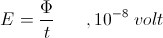
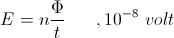



          Compounded on this relation is the number of turns in the coiled winding,


          And hereby it is,


          Where En is the volt per turn and n is the number of turns. No explanation is provided as to the reason for the reversal of the power of ten, from plus eight, to minus eight. We are off to a good start here!

          The number of turns in the winding act co-jointly to multiply the E.M.F. These turns also act co-jointly to the multiply the current. This current, i, in amperes, is continuous throughout the coiled winding. As each turn comes about it carries current, i, with it, round and round again, throughout the total number of turns. The net result is a sheet current, this consisting of n individual currents. This is given by the relation,


          This sheet current is the magneto-motive force that maintains the magnetic induction. This is in distinction to the current, ii, and the number of turns, n. For example, a reactance coil has 1000 turns, and it is drawing a current, i, of one ampere, the sheet current of the coil, is, is now 1000 amperes. Hence this coil is operating with a M.M.F. of 1000 ampere-turns. Large M.M.F.'s can be produced with small currents thru the compounding of these currents via multiple turn windings of many turns. The limiting factor is the accumulation of series resistance as the winding gets longer in length.

          This was an important discovery in electro-magnetism. It's first engineering application was the Morse Telegraph Coil as developed by Joseph Henry, the American Faraday.

          (2) These multiple turns not only multiply the current, i, they also multiply the E.M.F., E. The currents compound, side by side, in a parallel fashion, this creating a sheet current. The E.M.F. per turn compounds, end to end, in a series fashion. Each and every turn develops an identical E.M.F. All turns are linked together thru the mutual magnetic induction which surrounds the entire winding. Each individual E.M.F. adds to the next, in a series manner, developing a total E.M.F., that of the entire winding.

          This is expressed in the relation,


          Where,

          Eo, the total end to end E.M.F.

          E, the individual turn E.M.F.

          For example, the same reactance coil, 1000 turns. This coil is discharged at a constant rate over a period of one second. During this discharge each turn develops an E.M.F. of one volt. The coil has 1000 turns, hence the total E.M.F. at the ends of the windings is 1000 volts. This is the principle of automobile ignition coil, a magnetic discharge device.

          Here established is two relations, one for the total M.M.F.,


          The other for the total E.M.F.,


          The individual currents are identical thruout the coiled winding, no gradient exists in this current. The individual E.M.F's are also identical, but not as with the current. A gradient exists in between the turns as the E.M.F. compounds along the winding. Hence a voltage gradient exists along the winding length expressed as volts per turn. Here in this metallic-dielectric geometry the magnetic force and the dielectric force are oriented in the same direction, (MK).
          Last edited by t-rex; 07-23-2012, 11:14 PM.
          SUPPORT ERIC DOLLARD'S WORK AT EPD LABORATORIES, INC.

          Purchase Eric Dollard's Books & Videos: Eric Dollard Books & Videos
          Donate by Paypal: Donate to EPD Laboratories

          Comment


          • #50
            The Law of Electro-Magnetic Induction, Part 5. (2 of 2)

            (3) In chapter three, page 16, Steinmetz gives the dynamo formula for the average value of E.M.F. as,


            Where,

            FF
            SUPPORT ERIC DOLLARD'S WORK AT EPD LABORATORIES, INC.

            Purchase Eric Dollard's Books & Videos: Eric Dollard Books & Videos
            Donate by Paypal: Donate to EPD Laboratories

            Comment


            • #51
              Originally posted by Nhopa View Post
              Based on measurements do any of the "builders" have some feel for the approximate size of capacitor we are going to need for the primary if the secondary coil is designed for around 1,000 Kc. I am thinking of using mica for the dielectric and copper plates. 1 mm thick glass would also be good, but I can't get it where I currently live. Has anyone tried yet to glue the plates together?
              When using silver mica caps in parallel I need 6 - 330pF caps for 1620.

              Just Install your primary and use caps in parallel to find out how much you need. This will get you in the ball park. Then build your plate cap.

              Comment


              • #52
                Law of Electromagnetic Induction, from Steinmetz T&C of AC Phenomena

                No explanation is provided as to the reason for the reversal of the power of ten, from plus eight, to minus eight. We are off to a good start here!
                I may be wrong on this, but I believe Steinmetz prefers the use of the maxwell instead of the weber for the unit of magnetic flux, at least for introductory explanations. This is why the use of 10^8 and 10^-8 make their appearance in his engineering expressions. Whereby 1 maxwell is a single loop of magnetic flux and one hundred million, 100,000,000 or 10^8 maxwells cutting a single turn conductor per second is one volt of E.M.F.

                It is that one weber cutting a single turn conductor per second is also one volt of E.M.F. This relates the two by the factor of 10^8 or one hundred million maxwells is equivalent to one weber. Thus Steinmetz's expressions are confounded by 10^8 and 10^-8 due to the choice of unit for the measurement of magnetic flux. This is probably obvious to most, but I thought I would help clarify for those who are new or unfamiliar with this subject.

                Concluding, Steinmetz starts off with the explanation in maxwells or "lines" but then converts this into webers by the use of 10^-8. I believe this is done to develop the significance of a single loop of magnetic flux, or one maxwell, while at the same time keeping the discusion relevant by making the expressions equivalent to units in webers. However, this portrayal may seem like a nuance to some, due to the added mathematical baggage needed to keep everything in order.

                A helpful companion reference for this topic is The Magnetic Circuit 1911 by Vladimir Karapetoff. Given below are pages 6-7 of Karapetoff's book, which covers the differences between the maxwell and the weber:


                Also, I thought I would put up the referenced pages of Steinmetz's book, Theory and Calculation of Alternating Current Phenomena, for quick perusal by those interested in the T-Rex Transmissions:


                Garrett M
                Last edited by garrettm4; 08-06-2012, 05:32 PM.

                Comment


                • #53
                  Primary coil

                  Hi jake, dR-Green and all your other experimenters:

                  Just a thought, what if I would place the primary coil right over the secondary? Tesla in his Notes, page 68 states "...the secondary will have to be placed in the closest possible inductive relation to the primary and this will give...., of relatively high frequency, since the inductances of the circuits by mutual reaction will be considerably reduced.". Now Tesla's set up was such that allowed him to make quick changes in his coil geometry. A primary over the secondary would not yield this kind of freedom of variation for coil configuration. Any thoughts?

                  Comment


                  • #54
                    Originally posted by Nhopa View Post
                    Hi jake, dR-Green and all your other experimenters:

                    Just a thought, what if I would place the primary coil right over the secondary? Tesla in his Notes, page 68 states "...the secondary will have to be placed in the closest possible inductive relation to the primary and this will give...., of relatively high frequency, since the inductances of the circuits by mutual reaction will be considerably reduced.". Now Tesla's set up was such that allowed him to make quick changes in his coil geometry. A primary over the secondary would not yield this kind of freedom of variation for coil configuration. Any thoughts?
                    That's how it is (shown) in patent 1119732.

                    Patent US1119732 - ELECTRICAL ENERGY - Google Patents

                    Maybe this is the direction he was heading? At the same time, I don't remember where I read it, but Tesla mentions somewhere that he wanted the loosest primary-secondary coupling to allow for resonant rise in the secondary, which is why he developed the conical coil from the flat spiral I think, and then what led to the necessity of the extra coil (??) in the CS type setup. Not 100% certain but I think that was the general direction, I get the impression that changes are made, then other things need to be done to make up for the loss of performance or difference in the geometry etc. So maybe once the extra coil was done he could take a step "backwards" again, not needing the loosest primary-secondary coupling any more.

                    Just some thoughts on the matter.

                    [edit] Although I would expect the magnification factor of the secondary to be a lot lower that way. The secondary would be more ready to respond to a wider frequency band rather than a sharp peak at the resonant frequency. But where I get a bit lost is that the basic transformer action wouldn't be as efficient when they're further apart. So as with everything here maybe there's a particular distance where it will all be perfectly tuned.
                    Last edited by dR-Green; 07-24-2012, 06:55 PM.
                    http://www.teslascientific.com/

                    "Knowledge is cosmic. It does not evolve or unfold in man. Man unfolds to an awareness of it. He gradually discovers it." - Walter Russell

                    "Once men died for Truth, but now Truth dies at the hands of men." - Manly P. Hall

                    Comment


                    • #55
                      The Law of E.M. Induction, Part 6 (1 of 3)

                      (1) Steinmetz closes chapter three in his A.C. book, 1916 edition, with his development of the concept of Inductance. Here given, for the first time in chapter three, is the current, ii, in effective values, an unnatural form. The relation is given by,


                      Hence the resulting expression is given by,


                      Transposing his relation gives,


                      This derives from Steinmetz's expression the co-efficient of self induction.

                      Using maximum rather than effective values for current simplifies the relation to,



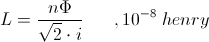
                      This the basic expression for the co-efficient of self induction.

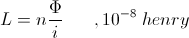
                      (2) This self induction is a non motional, or static, induction. This represents the reactance coil. It is important to notice that the self induction is distinct from the motional induction produced by the dynamo. The motional relation, that of rotary motion, is given by the relation,


                      The induction for the static, or stationary, condition is given by the relation,


                      In the static expression the number of turns, n, and the factor of ten to the minus eighth, are absorbed into the henry, that is,


                      becomes


                      (3) Continuing in chapter three Steinmetz introduces the concept of Reactance. The relation is given by,


                      Substituting the relation,


                      Establishes the basic Ohm's Law expression for alternating currents,


                      X is called the reactance of the coiled winding. Transposing gives the expression for the reactance as,


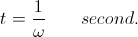
                      And it is that volt per ampere defines the dimensions of the ohm. This volt per ampere can also be expressed as a henry per second, giving the relations,


                      And it is,


                      This expression of reactance can be considered a synchronous inductance, this in an A.C. circuit.
                      SUPPORT ERIC DOLLARD'S WORK AT EPD LABORATORIES, INC.

                      Purchase Eric Dollard's Books & Videos: Eric Dollard Books & Videos
                      Donate by Paypal: Donate to EPD Laboratories

                      Comment


                      • #56
                        The Law of E.M. Induction, Part 6 (2 of 3)

                        (4) The total magnetic induction can be sub-divided into a pair of independent factors.

                        One, the intensity of the magneto-motive motive force, this maintaining the quantity of magnetism, Force, i, in ampere.

                        Two, the concentration , or inductance, containing the quantity of magnetism, Concentration, L, in henry.

                        These two factors are related thru the Law of Magnetic Proportion, given by,


                        Where, i, is the ampere of current. Transposing gives the relation for magnetic induction as,


                        Hence the total magnetic induction is the product of two Independant Parameters, each of which contributes to the induction. Each of these two parameters can be varied separately. The E.M.F. is developed thru the resulting variation of the total magnetic induction.

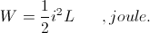
                        The total energy contained in the magnetic induction is given by the relation,


                        It was given that,


                        Substituting this into weber-ampere gives,


                        And this leads to the expression of magnetic energy as,


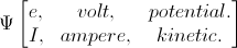
                        (5) The quantity of magnetic induction is made to vary by variation of the current or the variation of inductance, or by the variation of both. This variation of magnetism that results from the parameter variation gives rise to a variation of the quantity of stored energy contained in the magnetic induction. The E.M.F. developed by the variation of magnetism is the means by which the stored energy can either leave or enter its magnetic form. It is then the current, or M.M.F., represents the potential energy stored in the magnetic field, and the E.M.F. represents the kinetic energy given or taken by the magnetic field.

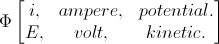
                        This is analogous to the dielectric field. Here it is the electro-static potential, e, in volt that represents the potential energy of the field. The displacement current, I, in ampere then represents the kinetic energy taken or given to the dielectric field. Hence,


                        Therefore where it is that the voltage, e, is the electro-static potential, it is the M.M.F. (and its current, i,) is the magneto-static potential.

                        Both potentials in themselves do not represent energy, only the force required to maintain this energy in a static, or potential, state.

                        (6) The M.M.F. is the force holding the magnetism in place. A stationary magnetic field needs a continuous current to remain stationary.

                        The inductance is the holder of the magnetism. An invariant inductance can hold a stationary magnetic field of induction in place.

                        Variation of either the M.M.F. or the inductance requires the magnetism move. This gives rise to an E.M.F. of energy transfer, this as a result of a time rate of change in the quantity of magnetism. The E.M.F. is directly proportional to this change, the quicker the change, the larger the E.M.F.

                        Neither the M.M.F., nor the inductance, represent energy. They are only factors of the induction, parts of a whole. While each parameter effects the magnetism as a whole, the effects of each are not interchangeable, and this needs to be taken into account regarding the Law of Energy Continuity.

                        (7) In the static reactance coil it is the intensity of force, as a current, that is made to vary. This variation is expressed in ampere per second,


                        Where,


                        The inductance of the reactance coil is constant, or invariant in this situation. Hence the E.M.F. developed by the reactance coil is derived from the time rate of current variation only. This is expressed by the relation,


                        Where, , ampere-second. It is customary however to express this relation using



                        and


                        But here in the reactance coil the inductance is in-variant, no such henry per second exists. It is the ampere per second which acts here. Hence in its common expression the term reactance can be misleading.
                        Last edited by t-rex; 07-25-2012, 03:00 AM.
                        SUPPORT ERIC DOLLARD'S WORK AT EPD LABORATORIES, INC.

                        Purchase Eric Dollard's Books & Videos: Eric Dollard Books & Videos
                        Donate by Paypal: Donate to EPD Laboratories

                        Comment


                        • #57
                          XL
                          Last edited by t-rex; 07-25-2012, 02:57 AM.
                          SUPPORT ERIC DOLLARD'S WORK AT EPD LABORATORIES, INC.

                          Purchase Eric Dollard's Books & Videos: Eric Dollard Books & Videos
                          Donate by Paypal: Donate to EPD Laboratories

                          Comment


                          • #58
                            T-Rex

                            I'm the diagam where you showed the CRI powering a bulb there is a metallic connection between the secondary and extra. Is this correct?


                            Edit:
                            Sorry I'm on a phone and I can't find that diagram to link to. But I wanted to ask while I still saw T-Rex on the bottom.
                            Last edited by jake; 07-25-2012, 03:13 AM.

                            Comment


                            • #59
                              Jake,

                              Eric is not close to a computer. Those past two posts are from manuscripts mailed to me by Eric.

                              @all,

                              My apologies on the recent data and getting anybody's hopes up. I have found that the control winding under study was being interfered with by another source of E.M.F. The results are null and void.


                              Dave

                              Comment


                              • #60
                                Originally posted by Web000x View Post
                                Jake,

                                Eric is not close to a computer. Those past two posts are from manuscripts mailed to me by Eric.

                                @all,

                                My apologies on the recent data and getting anybody's hopes up. I have found that the control winding under study was being interfered with by an

                                other source of E.M.F. The results are null and void.

                                Dave
                                Bummer on both of these.


                                But here is the diagram I was talking about. Does anyone know why in this setup the secondary and extra are joined.


                                Thanks,

                                Comment

                                Working...
                                X