This forum is preserved as a permanent archive. The community continues at eMedia Press.

Announcement

Collapse
No announcement yet.

My Motors got me to Tap into Radiant Energy

Collapse
X
 
  • Filter
  • Time
  • Show
Clear All
new posts

  • Cornboy 555
    replied
    Great to see you here Holbi, Welcome.

    Warm Regards Cornboy.

    Leave a comment:


  • Holbi
    replied
    Who am I?

    Hello Ufopolitics,

    Thank you for the acknowledgement.

    Originally posted by Ufopolitics View Post
    Excellent Testings Holbi!!

    I just hope you filmed this testings so we could see them all!!
    ...

    Excellent Holbi and Team...now, just for the record...because no one here knows we have been talking on private mails for a while...therefore they do not know who you guys are...and your credentials on this fields...

    Please, I am NOT asking for ANY Personal Private Info from you...nor your real names nor locations...(Eastern Europe is just fine Holbi...)
    I was graduated as electric engineer with a "summa cum laude" diploma and had a quite good background of mathematics and physics from different kind of students competitions, Olympiad etc., and had some non conventional electrical practical basics from different kind of self-made RF application but all this mainstream education is worthless to create a working free energy device.

    A some time ago I decided to re-learn all basics starting from Faraday, Ampere, Maxwell and Tesla. And I suggest be humble and open, that there's so much more, that you can learn.

    During this way I had realized even the electricity has not had a good working definition in "classical physics". Everybody are talking about electricity, everybody knows that electricity can shock somebody but what electricity really is? I did not find good definitions and descriptions.

    About my team ... coming soon.

    Regards:
    Holbi

    Leave a comment:


  • Ufopolitics
    replied
    Excellent Testings Holbi!!

    I just hope you filmed this testings so we could see them all!!

    1.) The 1N41418 diodes appears too weak to this circuit. We burned 6 of them.
    That Diode is there just to conduct readings at certain Low Pulses...if you go higher they will blow....it is a fast diode, but very low amps rate.


    2.) NTE576 was not in our supply chain so we used STTH12R06 (Turbo 2 ultrafast high voltage rectifier) instead of it.
    By the description:

    This is a 600 V / 12 A / 25 ns fast switching diode in TO-220AC insulated package.
    They were also burned in the both coil ends and in parallel with the switching transistor also.

    The measured current in the coil was not to high, few ampere only when the diodes destroyed.
    They will burn because of the "Dual Currents" creates a super fast environment because of being opposite to each others...too high for many strong Rectifiers to stand.

    We change the 1N4148 to the 1N4007 (1000 V / 1 A / ??? switching time) and
    STTH12R06 to the BY550 (1000 V / 5 A / 200 ns) and the circuit works well.
    Very glad You have found the right choice...

    May the 1N4007 is not the best alternative of the 1N4148 but it works.
    Well...if it works...don't touch that dial!...(American saying...means: leave it there, "as is" )

    The energy balance of the single coil circuit is quite well using DC output and resistance load.

    The output power measured on the light bulb with DC voltage and DC current was exact data.

    The input power was measured by oscilloscope and counted from the graphical form of current impulse drown from the 24 and later 36 V battery.
    Excellent!...actually we do not need much more voltages at input...

    The impulse frequency for the measurement was between 100 Hz and 800 Hz.
    THAT'S EXACTLY ALL WE NEED!...I have never written here, absolutely anything about Khz nor Mega Hertz anywhere!!


    The duty cycle was between 50% and 15%.
    The output power was between 5 W and 38 W.
    The coefficient of performance (C.O.P.) depending from the frequency, duty cycle, power supply voltage, load resistance was between 2.5 and 6.0.

    So, I can witness, even a single pulsed coil with the proper arrangement is possible in the small scale OU operation.

    Regards,
    Holbi

    Excellent Holbi and Team...now, just for the record...because no one here knows we have been talking on private mails for a while...therefore they do not know who you guys are...and your credentials on this fields...

    Please, I am NOT asking for ANY Personal Private Info from you...nor your real names nor locations...(Eastern Europe is just fine Holbi...)

    On another note...and reviving the past of this Thread (I believe is very worth now)

    A Single Coil is just the beginning of this whole deal...whenever we pulse a Coil (Looking at it from the Magnetic Field ONLY)...we create a "Magnetic Alignment" called a Field...that, is digested knowledge for many here for a very long time ago...what is new...is that by generating a magnetic field we are actually "aligning/invoking all kind of Aether Particles AROUND that Field, that stay there...just lingering...so, when we collapse our generated "artificially" field using Hot currents...we create a huge vacuum...that will "suck" with it all those outer aligned fields into our coils...and something I have called "A NEGATIVE INDUCTION" will take place in the same coil wires...traveling opposite to our collapsed flow.

    Now, where exactly in Geometrical Terms...will our generated field go?...The answer is the very center of that coil...a point in space...that we could call the coil "Gravitational Point"...set exactly equidistant from each ends...each magnetic poles...that's where it will disappear completely like magic...so to that exact point is where our Radiant Field will go towards also...BUT, reversed polarity...why?...because of magnetic relations...a North will attract a South...and a South will attract a North...simple stuff right?...so where there was a North...a South Radiant Field would be...and so on for the South...

    In Motors we have a disadvantage...when we deal with brushes...we must let that coil "go" without collecting till it reaches the next brush or output gates..

    But in Static State...we don't have that problem...coils are not going anywhere...


    Regards Friend


    Ufopolitics

    Leave a comment:


  • Holbi
    replied
    The STTH12R06 uses ST Turbo 2 600V technology and is specially suited as a boost diode in continuous mode power factor corrections and hard switching conditions.
    This device is also intended for use as a free wheeling diode in power supplies and other power switching applications.
    This is a 600 V / 12 A / 25 ns fast switching diode in TO-220AC insulated package.
    They were also burned in the both coil ends and in parallel with the switching transistor also.

    The measured current in the coil was not to high, few ampere only when the diodes destroyed.

    We change the 1N4148 to the 1N4007 (1000 V / 1 A / ??? switching time) and
    STTH12R06 to the BY550 (1000 V / 5 A / 200 ns) and the circuit works well.

    May the 1N4007 is not the best alternative of the 1N4148 but it works.

    The energy balance of the single coil circuit is quite well using DC output and resistance load.

    The output power measured on the light bulb with DC voltage and DC current was exact data.

    The input power was measured by oscilloscope and counted from the graphical form of current impulse drown from the 24 and later 36 V battery.

    The impulse frequency for the measurement was between 100 Hz and 800 Hz.
    The duty cycle was between 50% and 15%.
    The output power was between 5 W and 38 W.
    The coefficient of performance (C.O.P.) depending from the frequency, duty cycle, power supply voltage, load resistance was between 2.5 and 6.0.

    So, I can witness, even a single pulsed coil with the proper arrangement is possible in the small scale OU operation.

    Regards,
    Holbi

    Leave a comment:


  • GChilders
    replied
    signal breakdown

    @sawa25

    Just curious sawa25, what are you trying to drive at those kinds of speeds. The monster driver was really designed to drive asymmetrical motors. I imagine it will perform pretty well at speeds far beyond the requirements of the motor but that does seem excessive for the original design parameters of the monster driver. JS has a pretty good description at the beginning of his book on the problem with FET's. There is built in forces in conflict with clean operation that are opposing each other. Capacitance and resistance that create oscillations in the operations of the gate. Read it and perhaps you can find better, faster FET's that will meet your needs on your project. The coolMos FET's are among the best. The price goes up considerably depending on the parameters that you are actually going to need for your project. i.e. more speed, less heat resistance are going to cost much more from your wallet. Find what you actually need for your project and then purchase the parts to fit those parameters, they all break down at some point.

    Cheers

    Garry

    Leave a comment:


  • asollid
    replied
    2744

    Hi Dave what kind of meter is that across the switch. Do u have a schematic or sketch? Thanks

    Leave a comment:


  • Holbi
    replied
    CAD Software

    Hello Midaz,

    Thank you for the interesting.

    Originally posted by Midaztouch View Post

    Your CAD soft is very nice. Is there a CAD that you recommend?
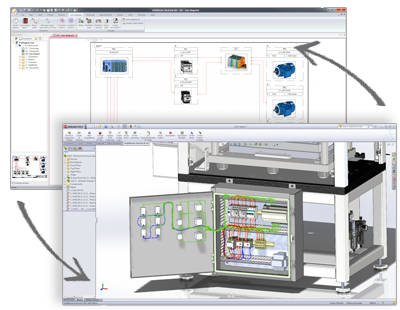
    I had been involved in different scientific research and development projects since 2009 and all of these projects were used the different versions and components of SolidWorks CAD/CAE environment.
    It was easy to learn how to use SolidWorks (there are good tutorials in the system and many youtube videos), so I continued to use it for other purposes also.

    Some part of SolidWorks available for free download (mostly viewers).
    Free CAD Software Downloads from SolidWorks
    And the full system is available with big discount for students and educational institutions.
    You can read more here: Student Edition Software | SolidWorks

    The biggest advantage of this system is the complex CAD for the mechanical and the electric part of the design. Designers can place 3D versions of all electrical parts into their model, and run wires/cables/harnesses in 3D to connect all electrical equipment. This feature is a big big help in the everyday engineering work.

    Also important advantage is a possibility of several simulation.
    Electrical Design Packages | SolidWorks

    Disadvantages of the system:
    - Does not run under Linux;
    - Big dependency from the Microsoft software components as MS Excel, Visual Basic, etc.
    - This is an expensive commercial system for design engineering.

    I tried to use also SolidEdge 3D (by Siemens) but I like SolidWorks better.

    And of course I had experiences with different 2D CAD system since late 1980's but now I use only SolidWorks. If you can access to these system I recommend to learn how to use it. You should go through all of the tutorials and do all of the drills and you will expert of the system by days.

    Kindest regards:
    Holbi

    Leave a comment:


  • Midaztouch
    replied
    Holbi

    Your CAD soft is very nice. Is there a CAD that you recommend?


    Keep it Clean and Green
    Midaz

    Leave a comment:


  • Holbi
    replied
    Minimal design for the redirect core

    Originally posted by Ufopolitics View Post

    1- I recommended small crystal diodes (IN4148) after the Ultra-Fast ones...they will "filter" some of the "craziness" ...However, at too high pulses they will definitively blow.

    2- I discovered a good tool to add to your meters...A Marine Generator Voltage Coupler/Adaptor:

    [IMG][/IMG]
    Important note: The North and the South part of symmetrically different parts to be able to connect them properly. If let we say, one of them left oriented, then the other pole should be right

    Leave a comment:


  • sawa25
    replied
    Originally posted by sawa25 View Post

    7.my bungling board
    last pics of board
    Attached Files

    Leave a comment:


  • sawa25
    replied
    Originally posted by JohnStone View Post
    Today we focus on final part F -the real power unit...


    Here R3, R9 come into play. They need to be tuned to be as low as possible and as high as to dampen oscillations. The value 1R is a place holder only. Some circuits need 5 Ohm others up to 47 Ohm. It can't be predicted.
    If you have no scope please use 22 Ohm or 33 Ohm and check for heat later on.
    If you own a scope you will start with 0Ohm (simple wire) and check for oscillations. Then you increase up to the state where you have no oscillations left. You will perform this test with resistive load i.e. a car headlamp connected to 12V. (see procedure below)
    Hello guys!
    I did my handpainted pcb of monster 5.1 (later on will buy from oshpark)
    and tried tuning.
    (i use signal generator with meandr,
    after opto the signal become weak and collapses at high frequency 460kHz,
    but after schmidt trigger, before micrel the signal is excelent up to 459kHz very good shape meandr(w/o load on drain/source))
    Still can't avoiding oscillation:
    Anybody, who succeded in this,please, advise; thanks in advance to UFOPolitics, Garry , you help much with my questions.
    So, questions about antioscillation resistors R3,R9, see pics(pic number and frequency in right bottom corner),
    - yellow probe - Source/Drain
    - Magenta - Source/Gate1
    -Blue - Source/Gate2
    with halogen lamp connected to 12V drain/source
    1. 10kHz, blue 10 Ohm, yellow 100 Ohm
    2.absolutly same oscillations with 60kHz
    3. same, but blue resistor disconnected from gate
    4.blue 10 Ohm and yellow 10 Ohm

    without load(lamp)
    5.gate signal good enaugh up to 230kHz
    6.gate signal 30kHz
    7.my bungling board

    i see, that the bigger the R3,R9- the less amplitude of drain/source oscillations, but more unshapely gate signal.
    in this circumstance i can't choose right resistor, because
    with 100 Ohm still oscillations, but gate signal almost breakdown.
    Attached Files
    Last edited by sawa25; 04-30-2014, 04:23 AM.

    Leave a comment:


  • GChilders
    replied
    dual stator program

    @Sampojo

    Hey Joe I am working on a throttle controlled program. It has already been written in a simplified form for Kogs. The RMC program provides for this although it is a more complicated program. At the top of the program just put in the number of brush pairs that you have on your motor. I have been busy with reworking my set up, and have not had enough time to test these programs as fully as I would like to. Hopefully towards the end of the week I will get a break. I have completed the all north wind for the goldmine motor and in my preliminary tests have mixed feelings about it. It does indeed accelerate under load when wired as ufo has it. Maybe my timing is off and so I want to play with the timing some more. Also like Kog's test on the Imperial it does not respond well under mechanical load when wired that way. It does extremely well with direct drive and I will test pulsing next and then post my results.

    Cheers

    Garry

    Leave a comment:


  • sampojo
    replied
    Using JS monster driver on dual stator asym motors

    Hi Ufo ,

    As you may know I am gravitating toward dual stator motors. So I assume it may be pulsed in sequence just like the Quad stator motors, but simply alternate between brush sets. I have an Arduino, but I don't think I have seen a program posted for a dual stator. When I get that far, I have a copy of the quad blink program. Is there a link at your site where perhaps several of these programs may be available that have been posted? Picking thru various programs to find the options desired is usually helpful. But I bet Gary C. could whip one out in his sleep Time has come to get some monster drivers assembled ASAP!

    BTW Dave45 and Holbi are some sharp fellows!
    Last edited by sampojo; 04-28-2014, 07:37 PM.

    Leave a comment:


  • Ufopolitics
    replied
    Originally posted by Holbi View Post
    Hello Ufopolitics,

    What is your opinion about power measurement of a single pulsed coil posted ?

    Kindest regards:
    Holbi
    Hello Holbi,

    I believe is great, excellent testing!

    On the issue you have on your meters going crazy...(and they could burn its processor too, so be careful!)...I found two solutions:

    1- I recommended small crystal diodes (IN4148) after the Ultra-Fast ones...they will "filter" some of the "craziness" ...However, at too high pulses they will definitively blow.

    2- I discovered a good tool to add to your meters...A Marine Generator Voltage Coupler/Adaptor:

    [IMG][/IMG]

    This device will detect True High Pulsed DC Voltage Readings, since it is made to detect any faulty Marine Outboard Engine Generating Coils...and as you know they work based on very heavy spikes sent to a very heavy duty Voltage Regulator (very expensive!)

    Maybe you do not have access to Snap On Tools...but I believe any Marine Engine Shop Technician...could direct you to the proper local manufacturer of similar tooling.


    Kind regards


    Ufopolitics

    Leave a comment:


  • Dave45
    replied

    Leave a comment:

Working...
X