
Frequency driver
Hi ZeropointEnergy,
Great result.
At what frequency are you driving your FET's?
(I don't mean duty cycle)
Bert
-
radiant colors
ZeropointEnergy,
Nice pictures zero,
The colors are beautiful. At night, when we look up at the stars, it's the same colors. So, we are told different temps are responsible for the different colors of the stars, but could it only be different frequencies of radiant.
Anyway, cool pics,
ThugLeave a comment:
-
Agree
Hey Ufo,Originally posted by Ufopolitics View Post
I also love that Magenta/Purple effect (depending on the frequency) that dances from the neon legs in fluctuations and then expands the bulb, many times
I do know of this potential and other properties. Friends come over to see it for a demonstration of the Radiant gas. They have all talked of this "Joy" or "content" feeling and I have even stopped people talking about who they fought on the weekend to prove to myself was not mind over matter. Or could just be the shock/amazement of the bright effects our brain does not fathom. Not 100% sure and more research is needed....Idk if it has happened to you...but I do feel them...
P.S: I'm glad you enjoyed the light show and you inspired me to obtain a few more colours in that show
Regards
Zero
Leave a comment:
-
Hi torpex,
Just found your message.
The capacitors for the motor in the video are wired in parallel with the motor on the cold side of the circuit.
The more uf I added the faster the motor went. I started with a lower uf and kept adding until it made no more difference.
I ended up buying a 10uf 250v as before I had alot of lower uf added together.
I think that those particular type of capacitors worked better than any other I tried, I believe they are Metallised Polypropylene, non polarised. I just tried different ones that I had on hand to start with until I found which worked the best.
Hope this helps.
neticaLeave a comment:
-
[QUOTE=Ufopolitics;200368]Hello Les_K,
"Please stay tuned because tomorrow, U.S Independence Day...I will be posting My Asymmetrical Motors here along with introductory video (Asymmetry to Enlightenment) that also contains many animated Graphics in 3D explanations ...I have spent many long hours creating this scenes,modeling, batch rendering, texturing... but they are necessary to understand Dynamic Machines...it is just impossible in a rigid 2D plane, observe three dimensional electromagnetic interactions as a whole...as it allows confusion and wrong understandings...
The Witch and her "spell" on Us all...will be broken and unveiled tomorrow... late afternoon, Eastern time US...The "riddle" of 132 years has been deciphered...and now that Witch (C EMF) will work for Us all...
"
Great timing, great moment
Cannot wait.
Good luck
BertLeave a comment:
-
Thanks UFO,
Working on the Ferris Wheel for the last couple years I am looking forward to any new insights you might offer to help me understand better.
I just heard that at the conference they released information on motors 100-200 watts per horsepower, That's pretty hard to believe but I am ready for the 4th... I'll be watching!
Larry,
PM me. I have some neighbors that bought an original Rife at of all places a garage sale. They reverse engineered the frequencies etc. and make the Tube.
LesLeave a comment:
-
Hello ZPE
Originally posted by ZeropointEnergy View Post
Hey ZEP,
Great, awesome pictures!!
I love that Purple-pure bright white color!!
However, I like all HER Wide Spectrum of colors, is awesome...it brings feelings along...Idk if it has happened to you...but I do feel them...
I particularly love to watch that little ball of plasma...dancing in between the Neon electrodes...
Great light show!!...
Regards
UfopoliticsLeave a comment:
-
Thanks, Les_K, You brought me Joy and Strenght!
Hello Les_K,Originally posted by Les_K View Post
Thank You Les, I am very glad that my work have been somehow of help to your development, it brings me lots of joy and also gives me the strength I need to keep going.
Please stay tuned because tomorrow, U.S Independence Day...I will be posting My Asymmetrical Motors here along with introductory video (Asymmetry to Enlightenment) that also contains many animated Graphics in 3D explanations ...I have spent many long hours creating this scenes,modeling, batch rendering, texturing... but they are necessary to understand Dynamic Machines...it is just impossible in a rigid 2D plane, observe three dimensional electromagnetic interactions as a whole...as it allows confusion and wrong understandings...
The Witch and her "spell" on Us all...will be broken and unveiled tomorrow... late afternoon, Eastern time US...The "riddle" of 132 years has been deciphered...and now that Witch (C EMF) will work for Us all...
See You all tomorrow, and excuse me if I have not answered so many great posts...I have been very busy...
Regards
UfopoliticsLeave a comment:
-
Hey Dana,Originally posted by prochiro View Post
Thankyou, I'm glad you enjoyed the pictures .
Coil utilized for the 1st July experiments was inspired from our emails.
150ft x2 of AWG #18 in parallel and equals, 2.2 Ohms per stands and 1.1 Ohms measured.
P.S: My new coils I had engineered are ready with the dimensions of 50x50mm and 50x75mm, both in clear Acrylic with 80mm ends.
Have room to add a >50mm (W) secondary coil, maybe even of CF.
Regards
Zero
Leave a comment:
-
Which effect?
Hey Ufo,Originally posted by Ufopolitics View Post
Which effect do you prefere since I didnt think you liked lighting neon lights only the CFL's?
I think the green effect is my prefered effects, even in the CFL. I'm more interested in the effects generated in the Neons at this stage and the colours associated with given frequencies.
What effects are more common in your experience if you dont mind answering, Green/White or Magenta/Purple
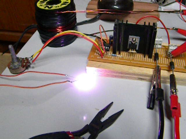
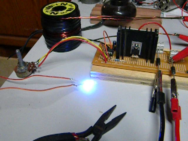
Also, did you like the Green/Yellow effects in the CFL?
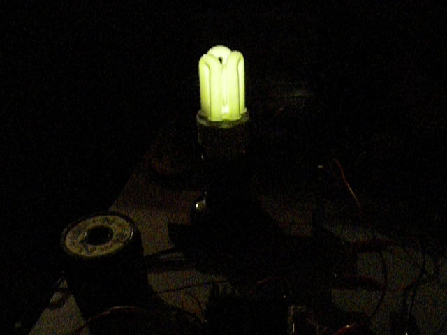
Regards
Zero
Leave a comment:
-
Hi Larry,
Your concern is understandable but fortunately not a real concern.
The FET is a FIELD EFFECT TRANSISTOR. The voltage is a means only for generating an electric field. If I could generate the field by any other effect (i.e. sound and piezeo or nuclear radiation.....) it would do as well. The only condition is the field between gate and source and this includes floating condition as well.Originally posted by larryross View Post
Imagine: A clamp squeesing a water hose performs its task of clamping at any hight you decide to lift it. Additionally we can open and close the clamp floating at any hight
In high voltage applications they put several FETs in series in order to add the individual VDS (max. drain source voltage) up to 10 and 20 KV.... It works well and fast. In so far the opto building block opens future applications with HV. Some special conditions need to be faced.
Imagine: Several consecutive clamps can be added to a pressured hose in order to face extremely high pressure. The optos are a kind of hydraulic gear in order to actuate the clamps simultaneously independent on their current position(floating) .
I do not go into details just now in order to not confuse and deviate from present basic goals.
The facts above are true for isolated gate drive. Drivers with voltage reference to GND are in fact NOT the genuine idea of a FET (though frequntly applied because of simplicity) and suffer exactly on their reference when performing as high side drivers. They have to lie in the bed you prepared for them.
Sometimes it is simpler to NOT overdo simplicity.
The facts above suggest that any additional resistor with reference to different voltage level will disturb the free movement of the source. It will add noise and possibly oscillations.Originally posted by larryross View Post
There are other influences we can not get rid of and that keeps the driver extensively busy. Any extended voltage pumping at drain leg (switch on / off) will have a genuine influence (capacitance drain / gate) The driver acts as body guard in order to prevent any disturbance to the soft slumber of the gate. No additional stress from outside accepted.
Once again: in case of isolated gate drive (opto or inductive or some other magic not discoverd yet....) the effect above is minimized!
If some of you have successful basic replications running and are bored and idling, eager for pioneering send a PM. You will get some application notes form FET manufacturers. But please consider - it is no basic stuff and I didn't try it myself yet.
Thanks for the hint. You are right. There are several items missing yet. As I mentioned before - it is eary early key hole view only. Thanks again for teh hints!Originally posted by larryross View Post
rgds JohnLast edited by JohnStone; 07-03-2012, 02:45 PM.Leave a comment:
-
preliminary optocoupler driver
thank you JohnStoneOriginally posted by JohnStone View Post
edit: to all...updates obtainable > in this folder < /editLast edited by s e t h; 07-03-2012, 10:47 AM.Leave a comment:
-
My gratitude
I want to thank Dana, Dadhav, Bob, and all for inviting me to take a look into this thread. I put it off for some time because of some experiments I was doing on my coils. I was stuck and since I was unable to attend this years conference I was very sad...
I was feeling down and Dana suggested I look here again so I finally did. To my great surprise this was the very solution to my blues, and my coil problem.
I was using a sniffer coil (John Koorn enlightened me to this) to see the field from end to end on the coils. The wave was 180 degrees out of phase at each end and null in the center. I equated this to the capacitance and inductance fields in a helical form along the coil. But when I read here that UFO (Thank you ) taught that the energy was inside the core my brick wall turned into a landslide of joy!
I see that many are using the fets here to do this experiment but I have been using the bedini cole bipolar switch for some years now and with my experiment, which is very similar to this I have had very very good success. I am using a opto on the front end that is driven by a frequency generator so I can adjust my pulse width and frequency very easily. After reading here that I was backwards I turned my square wave the other way and had it about 80% on with 20% off and to my surprise the trannies went very cold and the coil got very warm (Backwards from my conventional programming!)
UFO, from my opinion you have described things perfectly in line with all that I have learned from John Bedini and Tom Bearden. You have filled in so many gaps in the basics I have been missing. I applaud you sir and I look eagerly to learn great things. Yup! I am building a new coil based on this wonderful new knowledge...
Oh, and Dadhav and I are really looking forward to flying quadcopters for long flights!
LesLeave a comment:
-
CF
Hi UFO
I was reading tonight some reserch papers about carbon and its electromagnetic conduction and what I understand of this reading is that more may not be better. What I mean is this. It seems that as carbon is so superconductave that everything you throw at it is absorbed in the first few nm. I also read that adding more thickness may actually reduce the voltage. There is a lot to learn here and I am not done yet but it may be that all we need to do is heat shrink whatever we need to hook up the secondary coil, then rap only one layer on a cardboard core frame to place into core and then heat shrink another length to make the other connection. If I am correct, this should only take six feet of one inch wide by .005 thickness carbon per coil. This will be the subject of my next test and then compere with Bobs results also. I will know if it works this way or not in just a few days.
Dana
Leave a comment:

Leave a comment: