Announcement

Collapse
No announcement yet.

My Motors got me to Tap into Radiant Energy

Collapse
X
 
  • Filter
  • Time
  • Show
Clear All
new posts

  • adilu
    replied
    Originally posted by Ufopolitics View Post
    Hello Adilu,

    If you go to the first link I added "PROJECTS"...You will see how Gary writes his circuits...now below is what He writes...


    Therefore, that 1 MFD is a 1 uF, or ONE Microfarad.


    Regards


    Ufopolitics
    hello UFO
    tks for correction

    best regards!
    adi

    Leave a comment:


  • holtage
    replied
    parts list for circuit that can extract free energy needed

    Hi, UFOpolitics. I am holtage. I need to build a circuit that you mentioned in this thread which can extract free energy to power electrical appliances.

    Please reply me with a parts list regarding your circuit. It will be much better if the parts/components are available in ebay. I hope you can do me a favor by providing each ebay webpage address of each component needed to build your special circuit. Thanks, please DO REPLY!

    Leave a comment:


  • Ufopolitics
    replied
    Hello Adilu

    Originally posted by adilu View Post
    HELLO!
    i looked over wiki and 1 mdf is 1 microfarad (c1 condenser 1000uf 50 v in UFO circuit)
    correct me UFO if not right

    best luck
    adi

    Hello Adilu,

    If you go to the first link I added "PROJECTS"...You will see how Gary writes his circuits...now below is what He writes...

    3) In ALL my projects, All Capacitors are stated in "uF", (Microfarads) Unless otherwise noted.

    4) In ALL my projects, All Resistors are 1/4 Watt Unless otherwise noted.

    5) In most of the parts listings and schematics you find in these articles,
    I list resistors and sometimes capacitors with the multiplication factor within the values.


    Examples: 4K7 is a 4.7 K. 3M3 is a 3.3 Meg. 4P7 is a 4.7 Pf. 4u7 is a 4.7 uF

    100R is 100 Ohms 4R7 is 4.7 ohms (R = Resistance)
    Therefore, that 1 MFD is a 1 uF, or ONE Microfarad.


    Regards


    Ufopolitics

    Leave a comment:


  • GlenWV
    replied
    UFo'S circuit

    Greetings all,

    I have made a couple of replications of this circuit using Bob's drawing. These have worked well, and one is connected to 3k AH LA batteries and is making a difference.

    The coil used in that instance is wound bifilar, but not litzed. One end of the spare wire has a diode connected, and both ends are connected to a 11000 mfd cap. The cap is output to the input of one of Mr. Bedini's pulse chargers that I built. The setup does pretty good on lawn tractor sized batteries. Will try on larger batteries later.

    Next, is to scale this thing up and see how it does charging a 6700 AH battery bank. (Anyone been scaling up? Suggestions?)

    Thank you very much, Mr. UFOPolitics, I appreciate what you are doing.

    (yup, I'll get to the RS motor soon.)

    Glen

    Leave a comment:


  • adilu
    replied
    1 Mdf

    HELLO!
    i looked over wiki and 1 mdf is 1 microfarad (c1 condenser 1000uf 50 v in UFO circuit)
    correct me UFO if not right

    best luck
    adi

    Leave a comment:


  • Ufopolitics
    replied
    Originally posted by netpoint View Post
    Two questions ,(please forgive me if stupid):

    What is the symbol on the far left, "1MFD" ? Is that a decoupling capacitor?

    Is this circuit for a fixed pulse width duty cycle but adjustable freq? I only see the one pot.

    Thanks

    Dan

    Hello Dan...

    This circuit is NOT new to this thread...it is very well detailed by Me in my first pages ...
    It is a Condenser (Cap) not electrolytic...I use a Mica Cap...or a Tantalum which is polarized...I have to search, not sure now, but a regular ceramic will work there for sure.

    It adjust the Hertz output...as the Duty Cycle...in one Pot...Meaning the whole square wave pulse Width is Modulated, that is why it is called a PWM Controller...

    Regards

    Ufopolitics

    Leave a comment:


  • netpoint
    replied
    555 Circuit

    Two questions ,(please forgive me if stupid):

    What is the symbol on the far left, "1MFD" ? Is that a decoupling capacitor?

    Is this circuit for a fixed pulse width duty cycle but adjustable freq? I only see the one pot.

    Thanks

    Dan

    Leave a comment:


  • Ufopolitics
    replied
    Simple PWM Build...

    Hello to ALL,

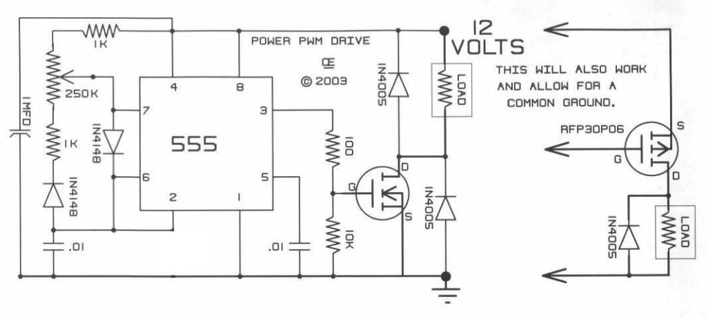
    I am presenting here the simplest PWM (Pulse Wave Modulator) and Motor Controller that you could build, it is based on the very cheap 555 Timer...and it could work "Safely"with up to 12 Volts...without the need of a Voltage Regulator.

    [IMG][/IMG]

    This is the circuit I have been using all along in My very First Thread, I just added an LM317 Voltage regulator that is posted in my other Thread, it consist of the Transistor LM317, a couple of Electrolytic Caps and a couple of resistors...and I did it in order to apply a Higher Input that ranges from 24V to 36 Volts...But the basic circuit is this one here.
    Timer works in the "Astable" Mode...rendering a very clean Square Wave...
    You will need this as a Controller to run from the very small Motors to the Bigger ones...so it is very practical...

    Also it will allow by just adding "Two Components" a Non Polarized Cap and a Diode...to make a SEPIC System that will control Input and Output from Machine Gates.

    I got this Circuit from: PROJECTS

    On:A Pulse Width Modulation Control

    I highly recommend this site for other great electronic free circuits as Switching Power Supplies and others...as Gary also sells parts there and the assembled circuits (for those that rather order them)...He is a very nice guy.

    I am not saying the other circuits are not good, on the contrary, the LM393 is a great circuit (Mad Scientist)...as it allows regulations of Duty Cycle and Frequencies...As also the great Modular Circuit designed by My Friend John Stone...However, they could become pretty complicated and all we are trying here is to Keep It as Simple as Possible...(note I did not write KISS... )

    To all the Members that have replicated my work:...I highly recommend to build this simple circuit...as it is the ONLY way you could see How My Machines Output True Radiant Energy Purple Plasma Sphere of Light...manifested at very low pulses...in the Electrodes of a 120 V Neon Bulb...


    ...and I know you will love HER...as SHE is the reason why we are getting all this "Phenomena" that many can not explain to be possible...then you all will understand better everything displayed here...as How I found HER originally...

    I believe it is a very lovely light you could not miss to see...


    Regards to all


    Ufopolitics

    Leave a comment:


  • Anoop
    replied
    Originally posted by Ufopolitics View Post
    Hello Anoop,


    The Motor Thread is there dear...and the small motor is the Radio Shack five pole...that was the first one I displayed.

    Check page 2 post 52 on...for that motor

    Regards


    Ufopolitics

    UFO: OK, thanks will take it from post 52. Thought I was missing something.

    UFO & Carroll: Sorry! I did ask for suggestions for a driver chip. Did not mean to cause confustion.

    Leave a comment:


  • Ufopolitics
    replied
    Originally posted by citfta View Post
    Hi Ufo,

    I am so sorry I have hurt your feelings again. In post 1362 of YOUR thread Anoop specifically asked if ANYONE knew of a suitable driver chip for mosfets. I only tried to respond to his question. Be assured it will not happen again.

    Carroll
    Dear Carroll,

    You did not "hurt my feelings" Dear...
    It was just exactly what I wrote there...however, I appreciate your desires to help Anoop...


    Regards


    Ufopolitics

    Leave a comment:


  • citfta
    replied
    Sorry

    Hi Ufo,

    I am so sorry I have hurt your feelings again. In post 1362 of YOUR thread Anoop specifically asked if ANYONE knew of a suitable driver chip for mosfets. I only tried to respond to his question. Be assured it will not happen again.

    Carroll

    Leave a comment:


  • Ufopolitics
    replied
    Citfta...

    Originally posted by citfta View Post
    To Anoop,

    I have had good switching time and full on and off control using the FOD3180 driver chip.

    Carroll
    Hello Carroll,

    Please do not advise my readers and members replicating here to use a chip where there is no one here that will be able to support them, there are NO circuits using that CHIP ON THIS THREAD. As no one has use it here at all.
    All you are doing is creating confusion by doing that...Hope You did not meant to...

    Will appreciate that!


    Ufopolitics


    To Anoop:

    Dear, disregard that chip (FOD3180)...We have no idea if it will work or not...

    Thanks


    Ufopolitics

    Leave a comment:


  • Ufopolitics
    replied
    555 Timer...

    Originally posted by Anoop View Post
    Hi again UFO,

    I've tried what you have suggested: Varying both the gate to source resistance (100K pot) and also the trigger to gate resistance (500 ohm pot, 100 ohm pot). Does not seem to make an improvement.
    I am driving a single FET with the coil disconnected and a simple load resistor in place of the coil, for this test. Am not using the heatsink as a bus bar for the Drain connection, but using the drain leg for this test.
    Maybe my FET's are not upto specs (?) will try obtaining from different sources and test again.

    Meanwhile can anybody suggest any common easily obtainable driver IC's to try? UFO, what do you feel the minimum switching times should be?

    In the past I've tried using mechanical relays instead of transistors for faster switching - however the high currents would cause the contacts to stick(!)

    Thanks and regards,

    Anoop

    Hello Anoop,

    So far I have been using the plain, simple and cheap 555 timers...and I love them.

    However, if you look on this thread there is also a Good circuit from Mad Scientist based on the LM393...This was reproduced by Bob French and Iankoglin.

    The Motor Thread is there dear...and the small motor is the Radio Shack five pole...that was the first one I displayed.

    Check page 2 post 52 on...for that motor

    Regards


    Ufopolitics

    Leave a comment:


  • Anoop
    replied
    Originally posted by citfta View Post
    To Anoop,

    I have had good switching time and full on and off control using the FOD3180 driver chip.

    Carroll

    Hi Carroll,
    Thanks, I'll look for this chip.
    Regds
    Anoop

    Leave a comment:


  • Anoop
    replied
    Originally posted by Ufopolitics View Post
    Ok, for all of you guys to know...I have opened an specific Thread on My Asymmetric Motors-Generators here:

    http://www.energeticforum.com/renewa...-machines.html

    Now, go to my post number seven (7) and read what we are going to do to those two little motors... and I also have uploaded some nice pic's of the "making"...I will post a small video later on tonight..

    Thanks and regards


    Ufopolitics


    UFO,
    Does this message still apply? Not finding the basic instructions for working on the two motors.
    Anoop

    Leave a comment:

Working...
X