-
That is GOOD! Thank you. It proves the point that higher speed reduces lenz after effect! -
Shorting vs Load.
@Overunityguide,
Thank you for your new video. You data is accurate enough enough to graph, and help explain to all our failed experimentalists why their results are poor or misleading. An RPM Laser tachometer is a necessary and extremely helpfull instrument for anyone attempting to replicate this effect with a pulse coil and rotor. My advice to all of them is not to give up. The Lenz delay propulsion effect is authentic, albeit a bit elusive. Persistence pays! Good luck.Leave a comment:
-
Nice demo OG (overunityguide,... not original gangster lol)
I look at your hands near the rotor most in the vid. lolLeave a comment:
-
I have done a second Video about the:
Delayed Lenz / Negative Lenz Effect for now:
The Difference Between Shorting and Loading
In which I show and clarify how you can get the regenerative acceleration effect when you Short your Generator Coil or when you try to Load your Generator Coil
So if you have any time left, here you can find it:
Delayed Lenz / Negative Lenz Effect, Difference Between Shorting and Loading - YouTube
With Kind Regards, OverunityguideLeave a comment:
-
Cook battery.
@SkyWatcher,
Here's a link to the original Cook battery patent that predates the Edison light bulb:
Daniel McFarland Cook's Electro-Magnetic Battery
Danial McFarland Cook called for either Ferromagnetic or Magnet core. The Ferromagnetic had to be magnatized before the capacative charge appeared in the twin bifilars coils.
The 400 turn 32 AWG bifilar synchro experimented with, had two powerfull 1/2" Neo ring tubes coupled end to end in the coil core. This would be half a Cook battery with an equal gauge seconday, instead of the 16 gauge called for in the patent. Synchro used the coil spool that Radio Shack wraps it's three color kinds of pre-packaged magnet wire on. The spool is 1" high with a 1/2 inch diameter core. Two 1/2" diametric neo ring tubes fit perfectly inside coupled end to end. The coil, shorted out to remove any charge generated from positioning, will begin to aggressivly store a charge while motionless if a super cap is wired in series to a fast switching diode between the leads. When the capacitor tops off, while still connected to the coil, it is ready to supply Lenz Delay Propulsion to the generator rotor. Simply shorting it may act as well. The capacitor can easily loop back to a 12 volt run battery and charge it while powering the Spinner or Rotor simply by connecting the capacitor ends to the correct battery electrodes!
The magnets in the output coil core will attract to the rotor or diametric spinner if positioned while stationary and result in a clumsey sticking issue. It's best to start the rotor or spinner first and gradualy approach with the magnet core coil. This gives the output coil a chance to generate an induced Lenz repulsion field that overpowers the attraction of the core magnets to the rotor magnets or the spinner. Once in position, the coil magnets no longer attract, but maintain coil capacitance charge that delays the manifestation of the induced Lenz pole untill top dead center, and the repulsion now powers the rotor as a pulse coil. This is a different way to achieve the Lenz Delay Propulsion effect with alot less wire, lower RPM'S,and lower and more usable voltage. Three posative advantages over a huge single wrap 30 AWG coil of 3600 feet in wire length like Overunityguide's or Nilrehob's that depend upon the natural formation of parasitic capacitance for their Lenz Delay impedence.
The magnet core Hi-voltage wrap variety of induced capacitance is much more powerfull then the long thin wire of many turns kind and offers the three advantages I already stated: Lenz Delay Propulsion with less output coil wire, at lower RPM'S, generating lower more managable voltage.Last edited by Allen Burgess; 09-04-2011, 11:19 AM.Leave a comment:
-
simple yet interesting...
I watched and thought about phase current lagging in the inductors. It is my opinion that a four channel scope is needed to line up the drive voltage and current on the first two channels and the driven voltage and current on the second two channels and do a good quality 360 degree graphing of this. Nice clean presentation...Leave a comment:
-
Hi folks, Hi Allen, could you explain further what this Magnet core Cook battery is and looks like, when you say magnet core, does that mean permanent magnet or ferromagnetic core, thanks.
peace love light
tyson
Leave a comment:
-
Bifilar capacitance.
Synchro's discovery was that a thin wire 32 guage bifilar coil, series wired in Tesla Hi Voltage, or "Joule Thief" fashion, generated a high coil capacitance when a diametric magnet was placed inside the air core. This charge developed spontainiously while the magnets were stationary. This effect the basis for the Cook battery. The magnet core bifilar output coil capacitance is much greater then the parasitc capacitance that accumulates naturally in a high inductance coil, and the Lenz delay propulsion effect much greater.
Synchro noted that the output coil magents were attracted to the rotor while standing still, but neutralized when producing Lenz induced poles while spinning. Synchro maintains that he was able to charge the run battery of his Bedini spinner by looping just one magnet core high capacitance 32 guage bifilar Lenz delay propulsion coil back to source. The coil ends were in series with a super capacitor and fast switching diode. Shorting this kind of high capacitance magnet core coil out would most likely create an even higher prime mover spin rate and reduced input.
The advantages to increasing thin wire output coil capacitance with diametric tube magnet cores are twofold: One, coil capacitance can be raised higher then with greater lengths of wire alone! and two, voltage can be kept to a lower and more managable range with less wraps and higher Lenz Dalay Propusion effect.Last edited by Allen Burgess; 09-04-2011, 02:30 AM.Leave a comment:
-
Lidmotor's Maggie.
Both Lidmotor and JonnyDavro have demonstrated the Lenz delay effect on the no bearing single magnet Bedini thread. Maggie, an air core output coil with a tiny flux activated magnet sphere spinning inside. The primary spinner accelerates, while the input drops when the magnet sphere output coil's placed nearby, close enough to generate power directly from the primary spinner. Maggie will continue to generate power at a greater distance from the primary's magnet flux alone.
Overunityguide's getting a Lenz Delay Propulsion Effect from a thin wire 30 AWG high inductance coil of many turns, 3600 feet worth. The parasitic capacitance is the charge between the wires that forms naturally and causes the Lenz delay. Lidmotors Maggie generates an internal Lenz delay propulsion charge internally from it's flux activated tiny spinning magnet sphere, and generates a much lower voltage output. That's the advantage! Here we see a core magnet increase coil capacitance and Lenz Delay Propulsion with much less wire and more useable voltage!
Synchro followed this discovery with another advance following experimentation with a Magnet core Cook battery, a single layer of 32 AWG primary covered with a 16 guage secondary wired in Tesla Hi Voltage series.Last edited by Allen Burgess; 09-04-2011, 02:24 AM.Leave a comment:
-
coil specs magnets and Hz
I think it is important with so many of us having different builds to start to compile very specific data.
to me these are important to nail down an optimal output
Hz - our best results were @ 9,369 magnet passes per second
1.924 Henry
323 ohms
31 or 30 awg can't remember most likely 30
9 welding rods as core
59mm long x 28mm wide
magnets are 3/8 x 3/8 round
the method we used is to physically add the coil while the rotor is spinning. our coil does slow the rotor down from 3253rpm to 3123 rpm. but as we all know the SSG ckt, the amp draw goes down as well and if properly tuned your charging should increase ever so slightly - I digress this is for another thread...
so there are the specs so far. when I get some time I'll post more on the outputs of the coil. we used it to charge a 12 and six volt battery. with each of these loads, the rotor only slowed slightly. w/o a load the rotor slowed down to about 2700 range. one other note
we put the core as close as we can to the magnets - my guess would be 1-2mm gap.

PatrickLeave a comment:
-
I have reduced the number of motor-coils on the motor to two,
this gives me more room for testing generator-coils,
and of course it's easier to work with.
To be able to measure the consumption of the motor i have been using this setup:

Its two SSG circuits, one normal NPN and one mirrored PNP,
this eliminates the charging battery normally present,
instead I use this energy for more torque.
By putting different resistance on the each generator coil i test
i have found out that there is a threshold for the size of the resistance
for which it is making the motor accelerate or decelerate.
If the resistor is less than the threshold it accelerates the motor.
Also it seems like the higher the inductance the higher the threshold resistance.
Another observation is that the voltage over the resistor is not a perfect sine-wave,
one side of the zero-line is sharper than the other side.
/HobLeave a comment:
-
As I am waiting for my build skills to increase I can't test this on my own, so I hope some of you would be willing to try and test something for me.
This is for those who have a pulse motor and have seen a generator coil load cause acceleration to the motor. Can you do a simple test and report the results please?
Flip the connecting wires to the generator coil and re-test. Record and post the change in RPM vs the change in RPM in the original design.
My guessing is that you will not see an increase in RPM. Perhaps even a slowing down. If I am right I would love to share my theory why. This may help others achieve the acceleration effect that haven't been able to do so yet. As for now I don't want to crowd peoples minds with a theory without data.
Note: remember that if your generator circuit has diodes or led's you will need to flip those as well. Thanks in advance.Last edited by Shadesz; 09-03-2011, 07:53 AM.Leave a comment:
-
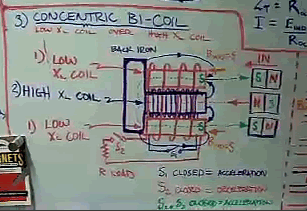
 Guest repliedIf the hi-impedance coil is not shorted when in the presence of an
approaching rotor magnet, wouldn't this disable an opposing polarity from
forming on the coil?? The way I've interpreted T.Heins presentation of
this technology in his NASA video, shorting the HV coil at the right
moment is some kind of key method.
With a generator coil surrounding the hi-impedance coil as it is shown,
their polarity of operation seems to be opposing eachother due to the
apparent direction of the switches S1 & S2, although following the way
each coil is drawn it looks as if they are both wound in the same
direction.
When the hi-impedance coil is only used for the sole purpose of
accelerating the motor and a generator coil is wound around it or
positioned at another location on the rotor, how might this change the
efficiency compared with using a single coil for both purposes?
Leave a comment:

Leave a comment: