
 Tweet
Tweet
Some time ago, I posted an analysis of Kapanadze's device and an idea how one may go about making a solid state version:
Because of my disappointing results when trying to use a counter-clockwise sliding coil over the long coil of my variation of Slayer's circuit, it looks like you need a pretty tight coupling between the coils. In my setup, I did not wind the short coil on top of the long one, but next to the long one, so my setup has a much weaker coupling between the coils, which is probably why I cannot light a fluorescent tube with my setup.
So, when I looked back to my idea of how to make a solid state Kapagen-like device (link above) and given that Kapanadze drives his coils directly and not trough a transformer, I think this may be a better design for a solid state Kapagen device:
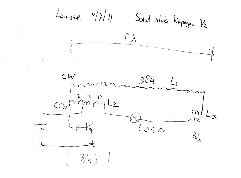
Looking at this, it occured to me that Kapanadze's spark gap draws a considerable amount of current from the coil, while he has a 3/4 lambda CCW coil at the left, and a 1/4 lambda CCW coil at the right:
Update: This is not completely accurate. The number of turns given leave room/variation for 20 turns in total, significantly more than the 12 turns that represent 1/2 lambda/wavelength and also more than the 18 turns that represent 3/4 lambda. When I posted the analysis linked above, I thought you needed an odd number of 1/2 wavelengths in total, while now I come to the conclusion you need a multiple of full wavelengths over the total length of the coils in series in order for the terminals you want to tap the power from to be in phase current-wise.
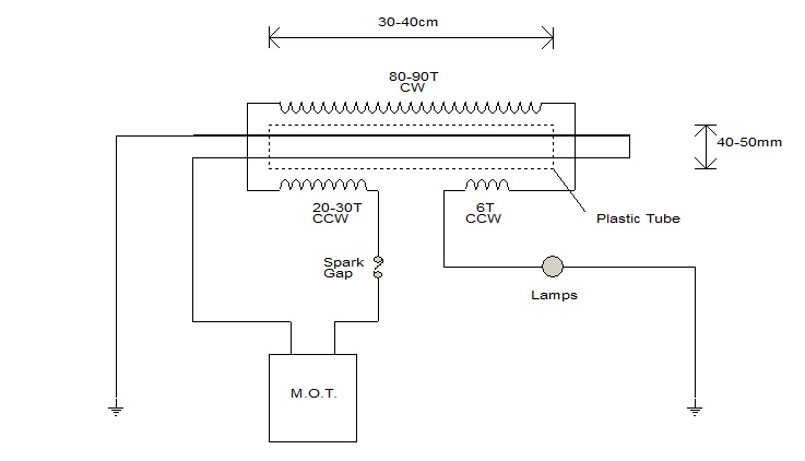
So, while I first thought he wound these coils counter-clockwise in order to kill the magnetic component, I now think it is because the two shorter coils are connected in the opposit direction compared to the main coil, so he apparantly wound these short coils CCW in order to prevent killing the magnetic component! Oops.
So, my conclusion for now is that all you need to do in order to get a current out of an oscillating coil is to make a coil a whole number of wave-lengths for the chosen frequency and to make sure the end of the coils are at a current hot-spot. Since, as you know, current and voltage have a phase difference of 90 degrees, it seems obvious that this is the way to do it:
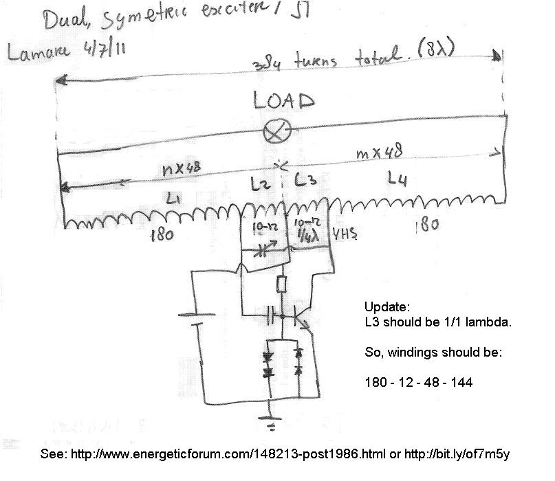
Since Slayer's long coil has a 384 turns in total and his short coil is 12 turns, we have 12 turns for 1/4 lamda/wavelength. Since the central tap is connected to the positive power supply, that point is a current hot spot, since it cannot be a voltage hot spot because it is connected to a fixed potential. So, every 24 turns away from the central tap, we have a current hot spot which are the points to try and tap current.
So, if we make a long coil such that a whole number of wavelengths fit in it, and we make a tap in the middle for the positive power supply and two more taps for the transistor feedback and driving connections, we should be in business.
In theory, L2 and L3 should be 12 turns if we take 180 turns for L1 and L4. Then, the tuning cap ( a few pF) should not be necessary. However, if you take 10 turns for L2 and L3 and add the optional tuning cap, you can tune the circuit for maximum output.
Have fun if you want to experiment with this!
Update: For more information about the negative resistance properties of a spark gap (oscillator) as used in the Kapagen device, as well as references to a modern negative resistance device known as a "lambda diode" as used in modern oscillators, see this part in my 'article' over at Pes:
Article:Free Electric Energy in Theory and Practice - PESWiki
Note that oscillators using a negative resistance device do not need a feedback signal as needed by a transistor operated device. In other words: with a spark gap or lambda diode you can oscillate a single coil, while for single transistor oscillators you need some form of feedback signal to the base of the transistor.
Update 2: Link mentioned in the image about coil windings: http://www.energeticforum.com/148213-post1986.html
Because of my disappointing results when trying to use a counter-clockwise sliding coil over the long coil of my variation of Slayer's circuit, it looks like you need a pretty tight coupling between the coils. In my setup, I did not wind the short coil on top of the long one, but next to the long one, so my setup has a much weaker coupling between the coils, which is probably why I cannot light a fluorescent tube with my setup.
So, when I looked back to my idea of how to make a solid state Kapagen-like device (link above) and given that Kapanadze drives his coils directly and not trough a transformer, I think this may be a better design for a solid state Kapagen device:
Looking at this, it occured to me that Kapanadze's spark gap draws a considerable amount of current from the coil, while he has a 3/4 lambda CCW coil at the left, and a 1/4 lambda CCW coil at the right:
Update: This is not completely accurate. The number of turns given leave room/variation for 20 turns in total, significantly more than the 12 turns that represent 1/2 lambda/wavelength and also more than the 18 turns that represent 3/4 lambda. When I posted the analysis linked above, I thought you needed an odd number of 1/2 wavelengths in total, while now I come to the conclusion you need a multiple of full wavelengths over the total length of the coils in series in order for the terminals you want to tap the power from to be in phase current-wise.
So, while I first thought he wound these coils counter-clockwise in order to kill the magnetic component, I now think it is because the two shorter coils are connected in the opposit direction compared to the main coil, so he apparantly wound these short coils CCW in order to prevent killing the magnetic component! Oops.
So, my conclusion for now is that all you need to do in order to get a current out of an oscillating coil is to make a coil a whole number of wave-lengths for the chosen frequency and to make sure the end of the coils are at a current hot-spot. Since, as you know, current and voltage have a phase difference of 90 degrees, it seems obvious that this is the way to do it:
Since Slayer's long coil has a 384 turns in total and his short coil is 12 turns, we have 12 turns for 1/4 lamda/wavelength. Since the central tap is connected to the positive power supply, that point is a current hot spot, since it cannot be a voltage hot spot because it is connected to a fixed potential. So, every 24 turns away from the central tap, we have a current hot spot which are the points to try and tap current.
So, if we make a long coil such that a whole number of wavelengths fit in it, and we make a tap in the middle for the positive power supply and two more taps for the transistor feedback and driving connections, we should be in business.
In theory, L2 and L3 should be 12 turns if we take 180 turns for L1 and L4. Then, the tuning cap ( a few pF) should not be necessary. However, if you take 10 turns for L2 and L3 and add the optional tuning cap, you can tune the circuit for maximum output.
Have fun if you want to experiment with this!
Update: For more information about the negative resistance properties of a spark gap (oscillator) as used in the Kapagen device, as well as references to a modern negative resistance device known as a "lambda diode" as used in modern oscillators, see this part in my 'article' over at Pes:
Article:Free Electric Energy in Theory and Practice - PESWiki
Note that oscillators using a negative resistance device do not need a feedback signal as needed by a transistor operated device. In other words: with a spark gap or lambda diode you can oscillate a single coil, while for single transistor oscillators you need some form of feedback signal to the base of the transistor.
Update 2: Link mentioned in the image about coil windings: http://www.energeticforum.com/148213-post1986.html

 I was just looking through my dad's box of components and I managed to find another 2N2222. But what's also frustrating/disappointing about this is that jonnydavro was using a 2N2222, but mine won't work. I know it CAN work because it did briefly with the BC182, so I see no reason why I shouldn't be able to get it going with the 2N2222
  I have yet to try it with the joule thief SEC circuit though so we'll see shortly, and I haven't tried the Darlingtons yet, that will be done within a few minutes too. On the Darlingtons though, the only place I've ever tried it so far was on my SSG, and it didn't like that at all, just kept coming to a halt. So I'm hoping it will be a bit more successful in this circuit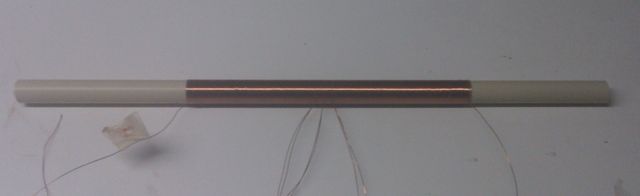

 The brighter the LED, the stronger the wireless field and how well it is all working.

Comment