
-
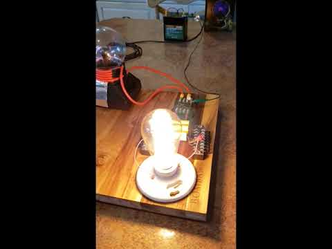
That bulb is illuminated in daylight, not a dark room. But whether it did or didn't, isn't the point. People expectations of some magical circuit to produce OU is not the right direction nor is it easy, or everybody could light a 10W bulb with a plasma globe emissions run from a 12V battery. I did it to show that Don Smith wasn't fake.
Last edited by ilandtan; 03-21-2022, 04:49 AM. -
Don Smith's devices are NOT too good to be true. They are actually working theories but have been bent so you can't get them to work. You won't find the answer here.
This is my replication and nobody can deny this is not working.
If you can't do this simple example, it's on YOU!
XRIXLeave a comment:
-
Hi Everyone,
"When resonance occurs in a parallel RLC circuit, a local current circulates between the inductor and the capacitor. This current can be very high, while the circuit current as seen from the source can be low."
Now I have made the first schematic of Hermes RLC-amplifier: It has a squarewave adjustable frequency generator and a constant current transistor. The transistor will be on when 4 is high and off when 4 is low. The 2k2 resistor is a current limiting resistor. The 100k potentiometer adjust the frequency. C Hertz capacitor alternativly charge and disharge. A big capacitor lower the frequency, while a small capacitor increase the frequency.
The transistor can be any small signal transistor with a safe output power of 625 milliwatt. The 22 ohm is a current limiting resistor limiting the transistor collector current to 0.75 Volt/22 ohm = 34 milliampere. The potentiometer that is connected between the 22 ohm resistor and the transistors emitter can be of any value. The higher value the less collector current. The transistor maximum output power is 9 Volts*34 milliampere = 300 milliwatt. The primary output between the collector and +9 volt source can be short circuit without burning the transistor. Also the secondary of the transformer can be short circuit without burning the transistor.
I see that Hermes RLC-amplifier can be used for three things. First find out if there is any larger current circulating between the capacitor and transformer in the RLC circuit. Second a frequency generator for free energy studies and third as a tester for suspected malfunctioning transformer.
Best Wishes, Hermes
Leave a comment:
-
837 Pages ??? wow thats huge !! I doin't think it has an equal - That Tariel bollix perhaps is the closest, remember the hands around the world bollix? Do they work ? can they possibly work? just m.h.o you understand - but overall and through the fog - Yes
why go there? OU has been achived over and over again -- why you want to tourture it some more ?Last edited by Duncan; 09-15-2021, 12:07 PM.Leave a comment:
-
Hi all,
I was researching Parallel RLC when I found this interesting page:
https://electricalacademia.com/basic...l-rlc-circuit/
"When resonance occurs in a parallel RLC circuit, a local current circulates between the inductor and the capacitor. This current can be very high, while the circuit current as seen from the source can be low. This phenomenon is used in induction heaters (in the industry for heating metals when necessary, e.g., heating bearings for mounting or dismounting) and in induction cookers (for domestic use).
In such an application a high current is flowing through an inductor, whereas the current provided by the power line is small. This means that the rating of the wires and breakers are much smaller than the current in the inductor.
The current in the inductor creates (induces) local currents in the piece to be warmed, without even touching it. In the case of an induction cooker, the body of the cooking pan becomes hot owing to local currents created by induction. This is shown in Figure 2.
The efficiency of induction heating is very high, and the process is very fast compared to conventional heating in which a great part of the energy is used for heating air and the intermediate media between the source and the body to be heated."
"In such an application a high current is flowing through an inductor, whereas the current provided by the power line is small"
The problem is the resistance in Parallel RLC. If it is small - the current in the inductor becomes less and I wonder if the current in the induction coil becomes less? if you add something to be heated? My idea is to replace the inductor with a transformer and somehow load it with a high impedance transformer? Can the transformer be loaded on the secondary without increase of current on the primary from the frequency generator?
I think I have solved the problem with the load on the primary side of an Parallel Capacitor-Transformer. Has anyone of you built a constant current pulse transistor as a primary for free energy generators? I am writing this idea, because I don't want anybody to file and be granted a patent on that idea.
The constant current pulse transistor does exactly as it sounds. No matter how much you load the secondary. The primary current does not change:
https://www.electronics-notes.com/ar...ent-source.php
Best Wishes, Hermes
P.S I think Don Smith used both parallel and series resonance in his resonance amplifer.
P.S these are the additional links I came across:
https://electricalacademia.com/Last edited by hermesatar; 09-15-2021, 12:33 AM.Leave a comment:
-
I am grateful for the info Zila shared about her success, but almost nothing she wrote is new as she admits herself and she made number of small mistakes some of which she's been called out for some of which not (listed below).
Core does not saturate at higher frequencies, it is the exact opposite, inductive reactance rises reducing current and flux density falls off with frequency, both reducing saturation.if u feed 35khz to iron core then core will saturate and heat up
You cannot calculate the RC cutoff frequency using time constant formula for a cap, notice she just swapped the time constant T with frequency 120. RC cutoff is ƒc = 1/(2πRC).if we desire frequency 120 cps(60 up and 60 down) then R =T/C =120/.008 =15000 ohms =15 Kohm(15 kilo ohm) wattage to be calculated by finding voltage and amperes. Since P=VxI
How? First what has the driving circuit have to do with resonant frequency of the Tesla coil. She is suggesting just use 80 turns of thin wire and it will resonate. Why would it. Of course it wouldn't. She first went with Don's advice, just make secondary 4x the primary and it should resonate, then she said ignore the wire length and just use turns ratio 1/4. Finally she admitted she had to "force resonate" it with caps. You could if you got very lucky.since ur custom made nst oscillating at 30 khz u dont need to use resonating length of Lpt=length of primary tesla coil just use 80 turns of thin wire 4000/80=50 volt per turn as primary it will oscillate at 30 khz
This makes no sense unless she is using a tiny cap on the primary side, like 30 nF. But i think she's using like 1uF microwave caps, that cap fed by output from a NTS or flyback at ~30mA can charge/discharge few times a second max. So what is then there to tune, primary rings ~10,000 times for every cap discharge. She says herself in other place NTS frequency is only for faster cap charging, of course, more peaks per second faster will cap charge to max V.when ur nst frequency matches ur primary coil spark gap fires else it wont fire
She also says in one place NTS frequency has nothing to do with your primary and secondary and in another she says it's a must they resonate.
Don't interpret this as defamation, i have respect for Zila, for a girl to make such success is great, it's just that she made some mistakes that needed to be pointed out.
However when it comes to scalar waves (misnomer since they do have a direction-vector) aka non-herzian waves or neutral waves, her knowledge in this area is very basic and flawed in some details. But more is not to be expected, it took me enormous amount of digging and correlation to come to more less complete picture (altho not fully complete, of course) of the phenomena. Let's just say truth is found inbetween Tassel, Zirbes, Keely, Hollingshead, Denaerde, Rota and Fry, all being key parts of the big puzzle + number of others of somewhat lesser import.Last edited by nix85; 09-18-2021, 06:20 PM.Leave a comment:
-
Hello ilandtan ..
in an attempt to find the correct geometrical device that linked directly to Tesla work i think we finally succeeded
image widget
the ETBC is a magnetic capacitor that combine both of Tesla system, a magnifying transmitter and a Tesla bifilar coil ( in case of 2D perspective )
building a large capacitor coil is a difficult stuff so there's a method that make it very easy and can be upgraded please see this video :
i think the drawing explain itself , when making such magnetic capacitor it's very important to make the inner turns smaller than the outer turns as explained in the presentation .
such device has a resonance frequency the point for maximum energy production, it's possible to use 3 coils , the input after that the magnetic capacitor and finally the output
this look like Tesla magnifying transmitter in local place..
about standing waves this device produce standing waves naturally due to the combination of capa / coil ..
some friend test show good result when using the ETBC as a secondary without resonance point ( i see it very important ) but still no huge gain !
thanks
regards
Leave a comment:


Leave a comment: