Announcement

Collapse
No announcement yet.

Gray Tube Replication

Collapse
X
 
  • Filter
  • Time
  • Show
Clear All
new posts

  • Aaron
    replied
    HV discharges out the diode

    Originally posted by geotron View Post
    Aaron, you're saying that the polarized capacitor bank is breaking
    down in reverse and releasing its energy though the anode? I'd like
    to give a non-polarized capacitor bank a try only to observe any
    noticeable difference.

    It seems as though I'll be able to tap the output of my voltage generator
    coil charging the CDI cap into a CW multiplier for boosting the LV side bank.
    Upping the number of transistors in the coil pulser will likely happen in
    this case to allow the additional current to speed things up.
    When the HV jumps into the diode (because it is completely open and
    is a path to ground for the HV), the reverse rating of the diode will be met
    and then it will close. The HV jumps the only other path to ground (gap
    to the rod/grid/point to the inductor). When it does that abruptly, it causes
    a strong negative suction on the diode's annode that pulls the positive
    charge from the LV cap out of it faster than an "ambient" discharge.

    You get that suction on that LV cap charge + the gap is ionized from the
    HV sufficiently to conduct that LV over the gap.

    The moment that happens you get the effect and the inductor charges
    and repels or attracts a magnet on a rotor depending on the polarity of the
    inductor.

    Leave a comment:


  • Aaron
    replied
    separate power supplies

    Originally posted by pranav2010 View Post
    is getting so much heated please tell me why this is getting heated

    and while triggering spark doesn't coming in tube its sparking in primary of the MOT

    i attached circuit diagram

    are you using two different power supply for HIGH VOLTAGE & LOW VOLTAGE

    and if i connect a dotted diode circuit doesn't work can you tell me why its happening
    My resistors got hot too. But you're working at 240v probably around
    the same amps so twice as much watts as me - maybe.

    The best way around that is to get an off the shelf CDI and power it
    with a 12v car battery and add diodes - will be an automatic plasma
    igniter for the front side.

    I saw the sparks in the video. Are you able to use an isolation transformer
    to isolate your MOT from the ignition side? I don't know if that is the
    problem.

    What is the rating of the diodes leaving the MOT? I used 2kv even though
    I used an output max of up to 1200-1300 volts or so but usually
    around 800. I used 8 diodes that were each 1000v 6a to make my bridge
    and that solved a lot of problems.

    I have used a common power supply on both the hv and lv side in smaller
    ignition tests and it worked fine, but I found that when upscaling this
    for these purposes that I really needed separate transformers.

    I used wall power direct thru diodes to charge the cap on the CDI front
    side system and I used a MOT on to charge the LV cap, which was
    4000v 2uf. But only charged that up to 1300 max.

    By the way, I fried 2 MOT's by melting the insulation on the wires - it isn't
    ideal but works great if you don't push it too hard.

    The dotted line - should work but may have interference by not isolating
    your MOT from the front side - have to think about it.

    Leave a comment:


  • Guest
    Guest replied
    opposing voltage suprise!

    Aaron, you're saying that the polarized capacitor bank is breaking
    down in reverse and releasing its energy though the anode? I'd like
    to give a non-polarized capacitor bank a try only to observe any
    noticeable difference.

    It seems as though I'll be able to tap the output of my voltage generator
    coil charging the CDI cap into a CW multiplier for boosting the LV side bank.
    Upping the number of transistors in the coil pulser will likely happen in
    this case to allow the additional current to speed things up.

    Leave a comment:


  • Guest
    Guest replied
    pranav - from your diagram it doesn't look like you've connected the grid
    onto a pathway to Ground. This might explain why the sparks are on your
    transformer...

    Leave a comment:


  • pranav2010
    replied
    testing of circuit

    hi aaron

    now my circuit is working its triggering very well but resistor 100 ohm 100 watt

    is getting so much heated please tell me why this is getting heated

    and while triggering spark doesn't coming in tube its sparking in primary of the

    MOT

    you can see this is my test video

    YouTube - VID 00008

    i think i am very close to your three point system

    please suggest me what to do

    i attached circuit diagram

    are you using two different power supply for HIGH VOLTAGE & LOW VOLTAGE

    and if i connect a dotted diode circuit doesn't work can you tell me why its happening

    have wonderful day
    Last edited by pranav2010; 02-26-2011, 03:22 PM.

    Leave a comment:


  • Aaron
    replied
    @Geotron

    Geotron,

    Good work! Saw the vid and from the pic looks like you're getting it!

    I have modified your diagram to be closer to what I have done.


    Basically, you're HV CDI side looks good.

    The difference I made is that I'm showing the HV rod
    is forced to go to the LV rod first to slam into the LV
    cap charged from a separate power supply.

    That LV is what I was cranking up to 1000v with a
    variac powering a microwave over power supply to
    charge that cap.

    Anyway, the HV CDI small plasma discharge from the HV
    side is forced to hit the LV side first. Then when the HV diode
    from the diode leaving the "LV cap(s)" closes shut, the discharge
    has nowhere to go but that third rod where the inductor is.

    When it does that, that LV cap is forced to follow over and the
    inductor charges creating a field that repels (or attracts) a
    magnet on a rotor depending on the polarity of the coil.

    Just as long as the HV CDI plasma ignition side has its negative
    connected to the negative of the LV cap and the negative of the
    inductor, you're good to go!

    Let me know if you have any questions - you're RIGHT THERE!

    Leave a comment:


  • Guest
    Guest replied
    tea laser on my list

    I'm understanding now a little better - that is very interesting to me the
    way in which to use a normal ignition coil with the diodes going from the primary
    into the output for generation of plasma. Its like using electrical leverage
    from the capacitor to propel the transformed voltage output.

    I've got a 500Mohm + 5.1Mohm voltage divider that I could hook up to the
    coil output, although with the nature of the burst being so violent I'm
    hesitant, thinking it might either destroy the resistors or my DMM.
    Otherwise I am uncertain what the value of my capacitor bank should be
    on the LV electrode. In order to find the ratio of input to output,
    I'm thinking I could possibly transist a signal through the ignition coil
    and measure both the voltage of what's going in VS the hv-output and use
    this to calculate what I would obtain with a certain voltage input from the
    capacitor of the CDI module.

    Aaron - In your video for the 3-Point Circuit I see that you max out your
    LV side cap bank to around 1000V, causing me to think that in this
    particular area, matching the output from the coil with 20KV or whatever
    in capacitor value is not necessary with the diodes sitting there to
    snap shut when their voltage limit is exceeded protecting the caps from
    damage. In truth I'm not yet certain in this area.

    I've captured a bit of action on my silent camera, and some stills as
    well. The following video [link] is set up exactly as shown in the diagram
    shown above. The electrode sitting on top is connected to the coil and
    is charging up the capacitor to around 1KV.

    After shooting this my signal generator was damaged for the transistor
    circuit driving the ignition coil into the HV end. It has since been replaced
    with one of my older models, of which I'm still getting the hang of. With a
    new version on the way and an old mot and extra 12v wall plug sitting around
    I'll be using this as my input to charge the capacitor.


    Anyhow, this is my newest illustration - with luck I've put your excellent
    tips to good use. Shown attached to the LV-side capacitor is something I
    thought might prove to be of some practical value... the diode going in
    reverse allowing flow in both directions even with the polarization. I've
    heard many times about the energy of this cap bank being drawn out into
    the spark gap and onto the mesh to power the coil, although how this could
    happen with polarized caps?

    Leave a comment:


  • SuperCaviTationIstic
    replied
    so no takers on the T.E.A. LASER analogy?

    Leave a comment:


  • Aaron
    replied
    Gray replication

    Hi Geotron,


    That is a post to that lawnmower setup for reference.

    The top black wire you have a question about is simply the negative
    of the ignition coil primary going to a bolt on the body of the engine for
    ground.

    The lower part you are asking about is indeed a resistor array. A bunch
    of series and parallel 100w 10ohm resistors I believe.

    To do it over again, I'd use an off the shelf CDI module from MSD or
    someone and hook it to the ignition coil and trigger it with a reed. With
    the diode string attached from ignition coil primary to HV of course.
    So you can convert any off the shelf CDI module to a plasma ignition with
    only the diodes.

    Anyway, in your diagram, the scr looks like it is pointing in the wrong
    direction - it is inverted. We actually had ours in the normal direction
    I believe.

    Also, we had a resistors on the gate.

    If you use this method, you'll get a basic plasma ignition.

    Then, simply use a separate power supply to charge a cap to a few
    hundred volts and a few hundred uf's. Make the ground common of
    course.

    Have that plasma ignition circuit jump to the positive of the other cap
    that is charged up over a gap then another gap to ground. On the way
    to ground, have the inductor there and that will run a motor.

    If you want to draw up the diagram, I'll comment on it.

    Anyway, I STRONGLY believe that anyone should focus on making a
    plasma ignition work first then go from there.

    Can you post any videos or pics of your plasma ignition?

    Anyway, I'm excited to see your results and hope Pranav is also getting
    some results!

    Leave a comment:


  • Guest
    Guest replied
    cdi unit

    I'm seeing now some interesting results Aaron with a few
    different configurations. I've felt a couple of small thumps
    on my electromagnet from 720V cap discharges to ground against
    the HV rod from which it was charging, and would like enhance
    my system with one of your nifty cap charger units.

    The following is a preliminary diagram I've drawn out to the
    best of my understanding - I'm not yet sure if it is a true
    representation.

    Leave a comment:


  • Spokane1
    replied
    The need for Lead-Acid Batteries in E.V.Gray Technology

    Originally posted by lamare View Post
    How does that explain the need for the batteries to be present, as Mark McKay said? :
    Dear Lamare,

    The Marvin Cole Engine was primarly an electrostatic device, at least as far as how the energy was extracted from it. Now there may be an RF process like what you are proposing to generate that OU in the first place, but once the non-classical energy gain was accomplished it was harvested using variable capacitors built within the motor. Three are three sets of variable capacitors that are composed of the three plates (that the electromagnets were mounted on including the cores of the electromagnets) on the rotor and nine similiar plates on the stator. The rotor plates were used in common for the three sets of three stator plates. Recent discovery of the EMA0 model has shead some interesting light on this wiring issue. It appears that the "Major" electromagnets were wired in a delta fashion on the rotor. I suspect the same system was used for the rest of the engine.

    Consider just one variable capacitor. In the position of maximum capacitance copious low voltage charge carriers are introduced into the rotor's common conductive assembly with its huge mass. It takes some mechanical energy to rotate the rotor out of this location of maximum capacitance to minimum capacitance. In doing so the voltage potential between the stator base plates and the rotor increases dramatically. At a certain time this much higher voltage is tapped off the staor plates to recharge the storage capacitors. Now, the low energy current carriers contain a much higher level of charge and therefore much more energy. This energy was provided by some non-classical event that is associated with the arc that is drawin across the surface of the dielectric inter-pole blocks.

    This approach is used in the construction of electrostatic motors. It also requires the use of blocking diodes. Since the charge carriers have to return to the source battery then the storage battery can't be eleminated until another solution is found.

    Another interesting discovery is the Delta circuit disclosed by the EMA0 model is that the topology is arranged so that each of the three control arcs in the commutator section of the EMA4 engine are operated with "Bidirectional Currents". This means that the arcs are supplied with current traveling in both directions. This dosen't happen in metalic conductors, but it can in an arc because both negative and positive curent carriers are avaliable. There is not much in the professional technical liturature about this kind of process, or at least not much that I have found in my extensive technical library. I have not yet built the apparatus to test this layout, but I shall report what I find (after I finish all the documentation I'm doing). It certainly is an interesting layout and one I would have not thought of on my own had I not had the model to look at. I would like to thank Mr. Ron Hammar for making this interesting and important piece of hardware history avaliable to me for study. This might prove to be the Rossetta Stone for this technology - at least from my standpoint. But, don't hol me to it. I alwasy get worked up when a new tid-bit like this comes along in this technology.

    I'm writing this all up [The Secrets of the EMA0] with several dozen drawings and photos (60+ pages I'm about 40% finished). Peter Lindemann will make it avaliable (I hope) for a small fee in a pdf format from his web site.

    It has now become apparent to me why Cole had to have so many unit power supplies with half-wave rectification. It has to do the with the isolation requirements needed to charge 3 storage capacitors that are wired in a delta configuration. At each apex of the delta is where the arc electrodes are placed to strike arcs to the delta connected inductive load of the rotor. Delta circuits are used extensively used in 3-phase AC systems, but it is certainly novel that it is being employed in a pulsed DC system - most interesting. Of course the patent doesn't breathe a hint about delta topologies, but the EMA0 sure tells its own story.

    I have also finished a 53 page report on the entire timeline of the developemt of all the Cole/Hackenberger Motor/Engines including a lot of circumstantial history and of course my personal speculations (which I have a lot of). Peter is editing this document now (since he is a writer and I am not) and will also offer it on his web site.

    This year has proven to be very productive. At last we have some techincal meat that we can explore experimentaly that actually has some relationship to the hardware that Cole was using.

    Spokane1

    Leave a comment:


  • lamare
    replied
    Originally posted by lamare View Post
    So, according to Patrick J. Kelly Grays technology did originate with Nikola Tesla, which we can speculate may have been the plans for Tesla's famous Electric Pierce Arrow:

    Tesla's Electric Car
    Another interesting reference to Tesla's car here, where JB also gives some hints about two different kinds of energy:
    John Bedinis' EV Gray power conversion tube - 06/05/01

    Received the following from John Bedini regarding Grays coils, the power conversion tube and what is going on with the motor;

    [...]

    Can anybody answer Me as to how these tubes work,,, NO BECAUSE YOUR LOOKING FOR THEM, YOU WON'T FIND THEM, and no one can make them if you do not understand them. TESLA USED THE SAME TUBES THAT RAN HIS CAR!!!!!!!!!!.

    I have also said that the school girl motor gave all the answers to the problem of free energy. Their is not going to be any kit that somebody can buy at radio shack, Research into this field takes real hard work. The Swiss machine uses the same tubes, WHY BECAUSE THIS IS THE ONLY WAY TO CHANGE THE FORM OF ENERGY TO SOMETHING USEABLE.

    Splitting the Positive what does this mean, it means that one lower form of positive energy is transformed into a higher form, but they are the same potential energy except useable now to do work "REAL POWER IN WATTS" or if you would say AMPS times VOLTS.

    I have made he statement to you before about the way everybody gets the FLUE the stuff that makes you sick, you just don't just get it, takes "TIME" Time is the key factor in pulsed motors(""" GRAY""")....

    IT TAKES TIME TO STORE THE CHARGE TO SOME POTENTIAL BEFORE YOU CAN USE IT FOR DISCHARGE into something. Into something meaning a storage battery or some load that the meters can measure. Closing the loop YOU CAN'T, free energy does not work this way, loops are never closed in any machine that's over unity.

    THE TWO ENERGIES ARE DIFFERENT because the two POSITIVES ARE DIFFERENT they are at the same potential but one weak, one collected and strong in discharge . Stored charge, Time, discharge to something , no closed loop, these are the keys to free energy , and it's not free you must work to get it. By the way the motor runs without the tube, just a little stronger with it and time delayed.
    More by JB here:
    Bedini advanced motor - 06/08/01
    Our engineering deals with electron movements this is "current". In a Free Energy system you must learn to use the opposite pure Voltage (pure potential), after it's working you must convert this into what are instruments see (ELECTRONS) to do this you must be very intuitive. But explaining all this just makes us one day older.

    Anyway I finally got a picture of a very high voltage power pulse inside a battery and it is cold boiling I can feel the pulse in heat out side the battery 3 to 4 inches away, but this is what it looks like (Pictures sent with this post) another thing this battery does is gain voltage under load, Haven't figured this out yet.

    [...]

    John refers to forward conversion, likening it to developing a pure potential which must be sent into a battery and cut off before actual current flows. Pure potential means a pure electric charge much like Hoopers motional field which used a moebius to cancel the magnetic component. John says he finds a PWM (pulse width modulator) circuit works best and when looking at the pulses on a scope they are exactly 180 degrees out of phase, showing 180 of electric, 180 of magnetic, alternating pulses.

    Very interesting, one can feel the pulses that come out of Bedini's motors, exactly what Tesla reported in relation to what he calls "distruptive discharge".

    Once again, if we remember that it is the electric and magnetic fields that cause mass-based currents to occur, while both can also exist on their own, it is clear that what Bedini calls "pure Voltage (pure potential)" is nothing but the electric field, that what causes electric currents to flow. And Bedini also talks about cutting "it" of before the actual current flows, which apparantly can be done in the case of a battery, because the ion charge carriers inside the battery need some time to react.

    Leave a comment:


  • Guest
    Guest replied
    (gasp) gapping autonomous spark

    Results are finally in! I've got a preliminary setup as shown here -


    This is a screen capture of the video I took showing how it works with
    a 2100V microwave capacitor connected on the coil charging up to around 750V.


    I'll be repositioning the coil-charging electrode further away from the LV side
    in hopes that it will magnify the effect. How this is working without the use
    of LV-side diodes is not immediately apparent to me...

    I've not yet tried sensing the effect with magnets next to the test coil, being that
    my 12V battery is decrepidly old and won't hold a voltage for long, so that will be another
    thing once it recharges.
    Last edited by Guest; 12-31-2010, 10:12 AM.

    Leave a comment:


  • lamare
    replied
    Originally posted by Aaron View Post

    Actually, I am using polarized electrolytic capacitors for the LV cap banks.
    And you have it in series with the coil....

    If indeed the ions inside an electrolytic cap cause a delay for currents to flow, then you have the essence of what Gray was doing. A HV sudden discharge into a coil causing a magnetic field because of the changing electric field during a short moment where there is not yet a current flowing, which is possible because the other terminal is loaded with some device containing an electrolyte fluid in between metal plates: an electrolytic cap, a battery or a WFC.


    Update: If it is correct that the excess energy effects are due to the combination of a coil and an electrolytic cap, it should also be possible to get an excess energy effect by using one spark gap and putting the whole train in series: HV Cap - spark gap - diode - switch - coil - LV Cap. If you take a relay for the switch, you should be able to pulse-charge the LV Cap using very little current from the source and gain energy which is tapped from the changing electric field being converted to a magnetic field in the coil during the brief moment the electrolytic cap needs for a current to get flowing.

    This may be worth a try, because with this experiment, we can determine whether or not the excess energy effects are caused by a delay trough the LV electrolytic cap, or by mixing of the HV and LV discharge trough the spark-gap.

    Update 2: Oops, that won't work to charge a cap. There is no path for the charge to flow from one plate of the cap to the other So, everything put in series would just create a series oscillation circuit with the coil and LV Cap, which would just ring for a while and dissipate all energy.
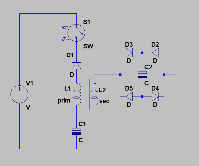
    However, if you would take the primary of a transformer instead of a single coil, you could a diode bridge at the secondary and use that to pulse charge a third cap.

    Update 3: See attached schematic for the idea. In this one, the switch acts as spark gap at the same time. When the switch closes, at some point you get an arc across the contacts, which should give you a sudden change in the electric field around the coil, even before any current can flow, which should give rise to a magnetic field in the coil, in proportion with the sudenness of the rise time of the voltage (see Maxwell, dE/dt). This magnetic field is then used at the secondary of the transformer to charge C2. C1 has no other purpose but to delay the moment a current starts flowing trough the coil and should be an electrolytic cap. Of course, V1 would be a high voltage source.

    Update 4: here's a high res version of the schematic:
    Attached Files
    Last edited by lamare; 12-31-2010, 08:54 AM.

    Leave a comment:


  • Aaron
    replied
    gray circuit comments

    Originally posted by geotron View Post
    Aaron, I am seeing now most of the things that have been confusing me, although
    in your following illustration there is something that remains a mystery.

    In some videos and images I've seen the use of polarized electrolytic capacitors,
    while you have clearly included non-polarized banks C1 & C2 for unidirectional
    flow. This tells me that I will have to build or obtain new ones that would allow
    this, with my current stock of those designed to only flow one way.

    My graphical interpretation is below - as can be seen I have included a second
    spark gap to give distance between them, while uncertain whether or not this is
    truly acceptable or not.


    Geotron,

    Actually, I am using polarized electrolytic capacitors for the LV cap banks.

    That diagram is a bit tricky as c2 is charged from the HV and when at a
    high enough voltage, causes the effect when HV hits it - again only when
    the c2 is charged from the HV. The inductor doesn't interefere with HV
    potential blasting thru it to charge c2.

    Anyway, c1 is even optional as well.

    If you have a capacitive discharge ignition as the HV and discharge
    that across a gap into c2, which is charged from a separate power
    source, you will get the effect. I'd just make the point going to ground
    closer to C2 than to C1 so c1 (CDI) is forced to hit C2 before going to
    ground.

    The inductor, I'd move it to the line going to ground. It works in either
    place though.

    Leave a comment:

Working...
X