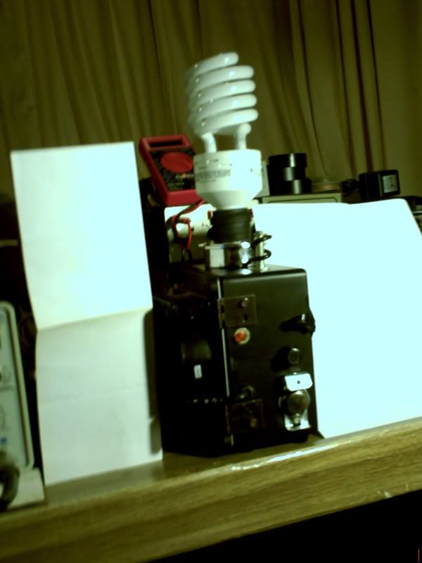
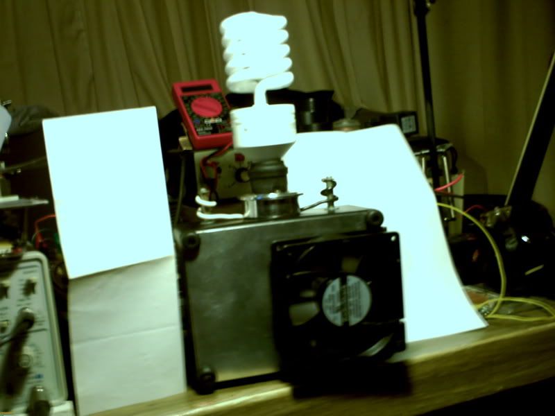
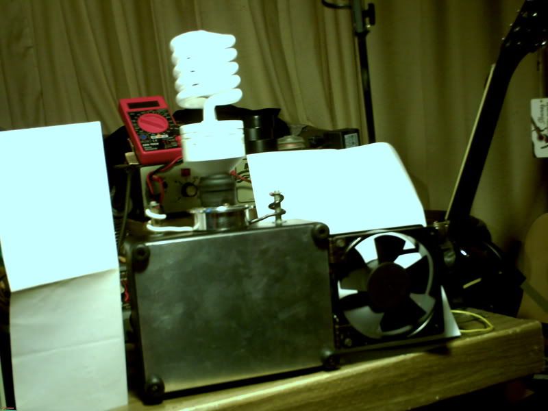
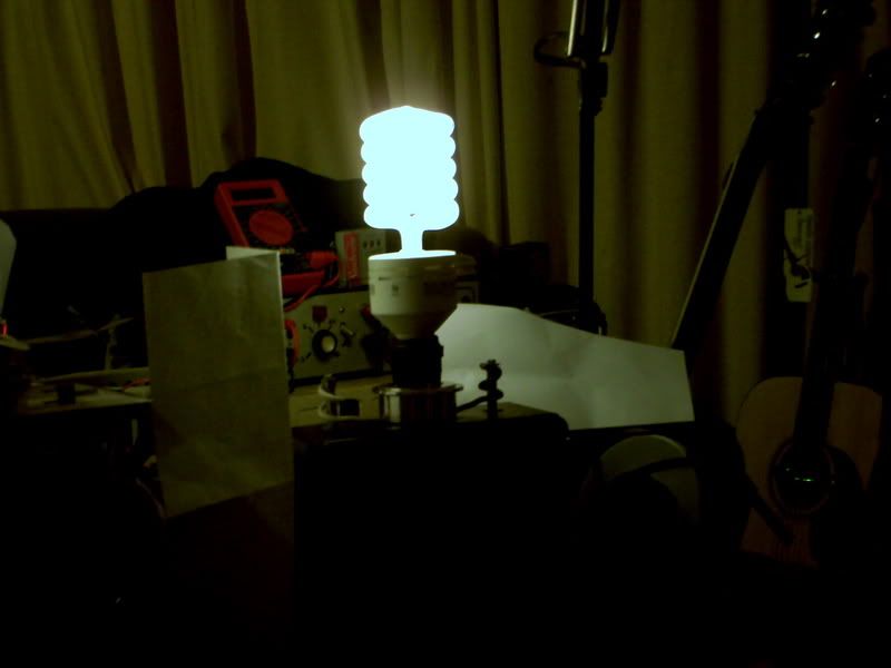
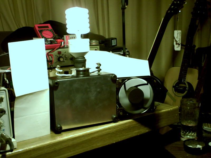
My setup is easily interchangeable for different circuits. I am going to Incorporate a flasher I already accomplished this before and got the part to do it. It can be used for signaling or Halloween..lol. I also will be including the solar panel for daytime charging as well. And coming up with a casing for the bulb so it wont get damaged in transit. Lots more work to go
Announcement
Collapse
No announcement yet.
Imhotep's Radiant Oscillator Video
Collapse
X
-
The globe is the ge 150 watt equilvant 2700 lumens. I run it at 2 light levels hi and low. Im still using the relay for high level light. But you cant hear it inside the box. i will be trying Ren's setup next.
My setup is easily interchangeable for different circuits. I am going to Incorporate a flasher I already accomplished this before and got the part to do it. It can be used for signaling or Halloween..lol. I also will be including the solar panel for daytime charging as well. And coming up with a casing for the bulb so it wont get damaged in transit. Lots more work to go
-
You are changing the inductance of the coil by placing iron/steel inside
You can actually tune it simply by sliding it up and down, kinda like a trombone
Check some of Tesla's patents, he used this to tune some of his devices. Your right Carl, air core is faster, because it doesnt have any steel to magnetize. Could be some interesting experiments with that. Multi tapped could be a little trickey. Id try making a couple of different coils, all around the 400-600 turn mark. Use different gauges for different models. The thicker gauge power wire will probably draw more, but charge better.
@ Agongon. Good work! Very neat diagram, I see you have been studying
(Please if you can repost the schematic including a note that its actually John Bedinis mostly, I dont want to take any credit for that.)
There is only on correction I might add at a glance. You are missing a 1uF cap in the 555 I believe. The 1uF you have marked should be 10uF and it smooths out the voltage to the 555. The 1uF comes off R2 to ground from memory, R2 is also 20k + 150k pot for varying dump frequency. Oh and you have draw a triac in place of the SCR, which I have never tried, but I believe will work fine. My model actually uses a MJL21194 there, seems to work better. Oh and there is a voltage regulator for the 555, so you can run up to 36v without damaging it.
A few changes Ive made since then.
Both coils on the main oscillator now meet at the collector, that is, there are two power coils now paralleled to the same transistor. Diode is off the collector in traditional SG fashion and goes straight to bridge after that. There is no bridge over the ignition coil, because it joins to the collector I saw no need for a second bridge there. There is a second bridge, but that is for the fan and its cap.
I now have two ignition coils, primaries wired in series and the light between the two HV outputs (center plugs). Light intensity increases and amp draw decreases. The other way the high voltage was allowed a path to ground via the CFL, now the only path that I can see is through the transistor, and thus the diode
@ Lid, that is a decent size cap. Maybe even double its capacity? You should get decent charging off that.
I did a charge test last night to see how well the back end battery held its voltage. With just the charger running (no light or fan):
Start Run:12.60 Start Charge:12.20
Finish Run:12.20 Finish Charge:12.82.
Drawing 250ma (lower than the batteries c20). Charge battery loaded up with a 300ma globe afterwards and it held its voltage remarkably well
Definately not a static charge
Good work people
Leave a comment:
-
Coil
The Mighty Ren,
Who got my SG going a while back, which kept me going, .....posed the question....... :-
.........What happens when you put iron in your air core?
So I tried it, and it lowered the freq from 3K to 1K.
Now I would like to determine what effect the turns ratio has on the air coil in circuit.
So I think I need to build a multi tapped air coil.
What say you all?
Carl
Leave a comment:
-
The BIG PICTURE CIRCUIT DIAGRAM
Thanks Agongon,Originally posted by Agongon View PostThis is my interpretation of Ren's setup using 12-volt sytem. I uploaded this schematic as a guide to beginners in electronics like me. Anyone can correct errors in this diagram. Only one coil is used here.
Like Bodkins, this makes a big difference for me to be able to see what is happening with that sort of a circuit diagram.
Imhotep,
Great build!!
Now that this is really taking on a usable look to it, more people are going to want to build it. I like the way you did yours with the fold away fan. With that CFL bulb sticking up in the air with those two "coil towers", it takes on a kind of Dr. Frankenstein's lab look. Put the bulb in flash mode and it would be great for Holloween. lol
Ren,
The cap I'm using is a 1000uf 50 Volt. I tried several like you and Bodkins advised and this one just seemed to be the one that worked the best with my simple pulser. As far as the caps on the coil are concerned, I tried taking the cap off on the Bedini Fan unit and it didn't work. It might be just my particular circuit. Carl has been playing around with it also. As far as building the 555 pulser circuit, thanks for the tips. I didn't have the right parts.
Waterhouse,
Miniaturization is where I'm at also as soon as I get this cap pulser figured out. I'm going to try a motocycle ignition coil when I can find one to cut down on the size and weight of the unit. I really like the Lithium batteries that I'm using now. Way to expensive though unless you can get them like I did on sale some where. The back end charging aspect of them is still to be determined however. I think Bedini says lead acid only if you really want his design to work right.

Cheers,
Lidmotor
Leave a comment:
-
thanks agongon i love the little picture it makes a bid different for me personaly.Originally posted by Agongon View PostThis is my interpretation of Ren's setup using 12-volt sytem. I uploaded this schematic as a guide to beginners in electronics like me. Anyone can correct errors in this diagram. Only one coil is used here.
one question what the duty cycle on the 555 and pulse rate?
Great work Sir
Leave a comment:
-
Coil
If we are getting better results by raising the drive voltage (24/36v) then getting more out of the coil in the first place would mean we could continue to use 12 volts.Originally posted by hh1341 View PostCoil overload............
The reason I bring this up, is........in an 8 cyl ITCE at 5000 rpm, the coil fires 333 times a second.
In my SS IROL replication, the coil fires 3000 times a second. I don't think the coil can keep up with this rate. I very much suspect the coil is not giving out it's 40,000 volt, rated voltage.
What say you all?
Carl
I would build a coil, if I had some specs. Or maybe try a voltage doubler.
Carl
Leave a comment:
-
Interpretation Of Ren's setup-[ 12-volt system ]
This is my interpretation of Ren's setup using 12-volt sytem. I uploaded this schematic as a guide to beginners in electronics like me. Anyone can correct errors in this diagram. Only one coil is used here.
Please proceed to post # 592. Thanks.
Leave a comment:
-
Great compact unit Imhotep!!
The only thing I have tried new is using 2 small 9v batteries in series to make a bright light with less bulky equipment..
Miniaturisation is my next mission
Lee
Leave a comment:
-
Preliminary operational emergency fan/light combo.
Its a 6 inch by 8 inch by 3 inch case. This first version can be ran off the fan electronics and relay. Pulser circuits to follow. More work to do.


The fan folds in for storage. On low light level it draws 400ma @ 12 volts. (SS) Fan and light running with 12 volt charge. High light level 700ma @ 12 volts with 12 volt charge. (Relay).
Leave a comment:
-
lol Ash.
Lidmotor, good work, you thought outside the square and figured out a way to pulse the cap. It can be frustrating trying to put together a small 555 circuit, but if you take your time and get the proper parts you may have more luck.
Look for a prototype solder board made specifically for IC's. The one I got is great. Room for 18 pins and it spreads them all out to make attaching simple. You can see it on my pics. The cap pulser isnt something you can just build and it is gaurenteed to rock straight out of the box. Im still finding out new tricks.
Whats the capacitance of your cap Lidmotor? And also, have you tried removing the caps off the Ign coils? I found that they smoothed out power to the light, but dramatically took away the charging ability.
Leave a comment:
-
Thankx Ren and Lid, et all. At the rate you guys are going your gonna solve the energy crisis by the end of the year
Leave a comment:
-
Cap Pulser
Ren I wish that I had a shed!!Originally posted by ren View Postmaybe not Carl, its enough to work with though.
I guess this thread is a little quieter because people are busy in the shed
I changed my setup to have two Ign coils and got better results again
I have it setup now like others have shown previously, where the lamp is between the two central plugs. This way it doesnt flow straight to ground. I start the charger and it draws 300ma. When the light is put on after warming up (10-20 sec) the draw drops to 270-80 ma. Charging isnt as pronounced, but still does charge. The way I had it arranged before with it flowing to ground it would start on 300ma and jump to 400 or so when the light was on.
Pic is 12v. 20w globe. Fan I adjusted too (Thanks JKoorn
) and it goes HARD now.

All I have is a dinning table and a kitchen countertop. Anyway I have been working on the cap pulser and have been very frustrated. I tried to make a simple 555 timer circuit yesterday and failed terribly. I didn't have the right parts, big hands ,bad eyes, wrong circuit board, a total disaster. So today I just threw together a crude pulser using a little motor thing that I got at a surplus store. It worked well enough to catch the principle. Sounds like everybody is busy. Here is a video of my very simple cap pulser that I made today.
YouTube - Imhotep Oscillator Fan/Lite--Pulse charging
Cheers,
LidmotorLast edited by Lidmotor; 09-09-2008, 01:46 AM.
Leave a comment:
-
maybe not Carl, its enough to work with though.
I guess this thread is a little quieter because people are busy in the shed
I changed my setup to have two Ign coils and got better results again
I have it setup now like others have shown previously, where the lamp is between the two central plugs. This way it doesnt flow straight to ground. I start the charger and it draws 300ma. When the light is put on after warming up (10-20 sec) the draw drops to 270-80 ma. Charging isnt as pronounced, but still does charge. The way I had it arranged before with it flowing to ground it would start on 300ma and jump to 400 or so when the light was on.
Pic is 12v. 20w globe. Fan I adjusted too (Thanks JKoorn
) and it goes HARD now.
Last edited by ren; 06-13-2009, 12:40 AM.
Leave a comment:
-
Coil Overload
Coil overload............
The reason I bring this up, is........in an 8 cyl ITCE at 5000 rpm, the coil fires 333 times a second.
In my SS IROL replication, the coil fires 3000 times a second. I don't think the coil can keep up with this rate. I very much suspect the coil is not giving out it's 40,000 volt, rated voltage.
What say you all?
CarlLast edited by hh1341; 09-08-2008, 03:28 PM.
Leave a comment:
Leave a comment: