
Excellent
Jetijs,
Very good. So, my predictions were pretty close.
From the scope shot it looks like we have this information:
Inductive rise-time = 1.5 divisions
Total ON-TIME at top speed = 3 divisions
Maximum current = 13 divisions
Total wave length at top speed = 17 divisions
Current wave-form at top speed occupies at least 75% of the area defined by 3 time divisions and 13 amplitude divisions. This area is also defined by the ammeter reading of 1.48 amps.
So, with the settings on your scope, we should be able to quantify these readings, even though we do NOT know the value of the resistor we are looking across. Also, we can cross-check your tachometer and scope time-base since the RPM should equal the frequency of the wave-form divided by four, since there are 4 pulses per revolution.
After reporting on this data, please move the ammeter to the negative side of the output (between the negative terminal of the battery and the group connection to the three output coils) and run the test again. This will show us how much energy we are recovering. In terms of current, it looks like you are getting about 1/3rd back, or about .5 amps, but at a higher voltage. So this time, please report the voltages of both batteries as well so we can compare WATTS in and out, not just current.
Great work!
Peter
-
Peter, I made the scope shots.
Here's where my amp meter is hooked up:

And this is how the current waveform looks like:

This is at full speed, drawing 1.48 amps at 24V.
And here's how the waveform looks like when I load the motor down:

As the motor is gaining speed again, the flat top of the wave gets shorter and shorter Last edited by Jetijs; 01-18-2008, 01:04 AM.
Leave a comment:
-
Making Progress!
Jetijs,Originally posted by Jetijs View Post
Very good. I'm glad the motor is stable in the new configuration and is operating the same with both output circuits.
The reason your transistors get hot when only one is hooked up is probably related to a combination of ON-TIME per cycle in relation to heat dissipation rate. When only one transistor is used, the magnetic field strength across the gap is probably under 400 ampere-turns. This turns the rotor slowly, so the transistors are in the ON-TIME window for a long time, drawing maximum current. With no heat sink, the heat builds up quickly. When all three transistors are used, the motor can speed up to the rise-time maximum quickly so the time the maximum current is across the transistors is very low. Your amp meter is sampling at a certain rate and since the RATIO of ON-TIME to OFF-TIME is always the same for the motor, no matter what speed it is going, it looks the same to the meter but is very different in the transistor.
Now, I'd like you to connect your scope probe across your amp meter. It has a low resistance shunt inside that it uses to produce the meter reading. We can use this also to look at the current on the scope. Then you will have both the AVERAGE current reading on the meter and the current wave form information on the scope, generated from the same source. The meter reading should be equivalent to the area under the curve on the scope in relation to the full cycle time. From this we can determine what the true peak current is that the transistor is switching.
The wave form should be a straight ramp up with a vertical drop-off. It will also have a flat top at start up which will get shorter as the motor speeds up. At full speed, the flat top may (or may not) disappear completely leaving the simple ramp or "saw-tooth" wave.
Let me know what you find.
PeterLeave a comment:
-
Yes Peter, you are right. I just tried the isolated output circuit again and with three transistors it works just the same. The battery on the output charges just as fast with both circuits and the RPM is the same. But why is that when I am using only one transistor for motor to run, the transistor heats up quickly, but when using three transistors, they get barely warm althought the total current draw has risen?
Thanks,
Jetijs.Leave a comment:
-
Next Test
Jetijs,Originally posted by Jetijs View Post
Excellent. Thanks for going back over everything and getting the motor running on all three transistors. 2383 RPM is pretty good speed for now.
Of course, I still recommend adding heat sinks to the transistors when you can and your idea of bigger batteries is also a good idea.
Now, I would like you to go back and hook up the isolated output on the other three windings. You will find that the second battery charges just as fast with this alternate set-up and that the motor operation is not significantly different. You can leave the current output arrangement in place, but disconnected. That way you can run comparative tests back and forth with each system to see motor speed and charge effectiveness with both ways. If you do go back and forth between these wiring set-ups, MAKE SURE that it is wired correctly each time you make the change or you can blow your transistors.
There is a reason I want you to understand this isolated output system because it makes certain other things possible later.
Great work,
PeterLeave a comment:
-
Hi elias
No, I have not measured the torque yet althought I have all I need to do this the way Peter showed in his DVD with those two little scales First I must be sure that I have everything right, I mean the rise/fall times and so on, only then I will measyre the torque. Also we need to measure how much power we are getting back in the charging battery, because when I see how fast the voltage rises on the charging battery when the motor is running, I am certan it is A LOT I guess this is why Peter says I need to get a large capacity capacitor
Also this motor wont have very much torque, because the air gaps are not as small as they should be, also the startor is attracting the rotor only 1/3 of a revolution, all the rest time the rotor is moving by its inertia and starts to slow down. Afterall this is only a conceptual design that shows us the principes and lets us learn
Edit: I made a new video:
YouTube - Lindemann attraction motor video3
Thanks,
Jetijs/Last edited by Jetijs; 11-25-2007, 06:14 PM.Leave a comment:
-
Congratulations
Jetijs,Originally posted by Jetijs View Post
Well done
Indeed you will be able to offer us a good estimation of the mechanical efficiency of Peter's designs and give us insight how to squeeze more out of it.
Your motor uses about 35 watts of electric power which means about one twentieth of a horsepower in conventional terms. Have you got any crude estimation of the mechanical power produced?
EliasLeave a comment:
-
Goodmorning everyone
Peter, as for the reedswitches, I am sure that the problem was the offcenter comutator, because when I could get only three pulses per revolution, I turned the comutator where the fourth pulse should be, and then if I pressed the comutator towards the reedswitch very hard, the whole thing bent a little bit, just to overcome the offcenter ( a half of milimeter or so) and the reedswitch did switch. Anyway, this is not important anymore, althought the reedswitches are good and easy to operate if you have your comutator right and everyone should start with them.
I did some experimenting. At first I disconnected and completely isolated all three outputwindings from each other and the circuit. I hooked everything up like in previous circuit without the isolated output. Also I put a computer fan near the transistors for cooling purposes. Again, I firstly tried to run the motor with only one transistor. Rhe RPMs were bad - only some 200 or 250 (i did not measure them) also the transistor got very hot fast and the fan could not handle that heat, the amp draw was about 0.8A at 24V (just like when isolated output was used). So I stopped the test.
Now I tried to run the motor with all three transistors. This time The RPMs were rising very fast and stabilized at about 2383 The amp draw was 1,48A at 24V. But the interesting thing is, that when using all three transistors, they did not get hot, only warm, nothing the fan couldn't handle. In the short test (a minute or so) the charging battery went up from 24.8 to 25.4V
Both batteries consist of two 7Ah 12v batteries in series. I should upgrade to bigger batteries, because this amp draw of 1.49A is not healthy for these little the batteries. Also the charging of the output batteries is happening to fast. I should charge and discharge them at C20 rate. But its good for short tests
Thank's
JetijsLeave a comment:
-
Deriving relationships
Aaron,Originally posted by Aaron View Post
This is very interesting, the only problem I see in it is the middle sliding part which may wear out over time and also waste some of the energy (I later on saw that it is claimed of no wearing out). I want to truly see if can an optimum geometry be derived using mathematical models, before attempting to construct something.
I'll keep posting as I find other interesting results.
EliasLast edited by elias; 11-25-2007, 01:14 PM.Leave a comment:
-
Thank you Peter,Originally posted by Peter Lindemann View Post
This was only a misunderstanding between us and its over for sure.
I am starting to read the book you recommended more carefully (Solenoids, Electromagnets, and Electromagnetic Windings) to understand how electromagnets behave exactly, to be able to derive more precise relationships.
I was thinking that there must be an optimum geometry for rotary motors as well as piston operated motors which utilize the most out of the electrical input applied to the solenoid.
By the way, can a motor cycle engine be modified to replicate Bob Teal's motor? I mean is it wise enough to buy a small motorcycle engine for modification?
Regards,
EliasLeave a comment:
-
possible optimum piston design for Bob Teal piston motor
Hi Elias,
I think both piston and rotary have their advantages and disadvantages like everything else. Certainly rotary is much more simple to build and 1 moving part... a shaft in bearings.
The most simple AND most highest torque motor per size that I know of with ONLY 2 MOVING PARTS... is the Bourke Engine:
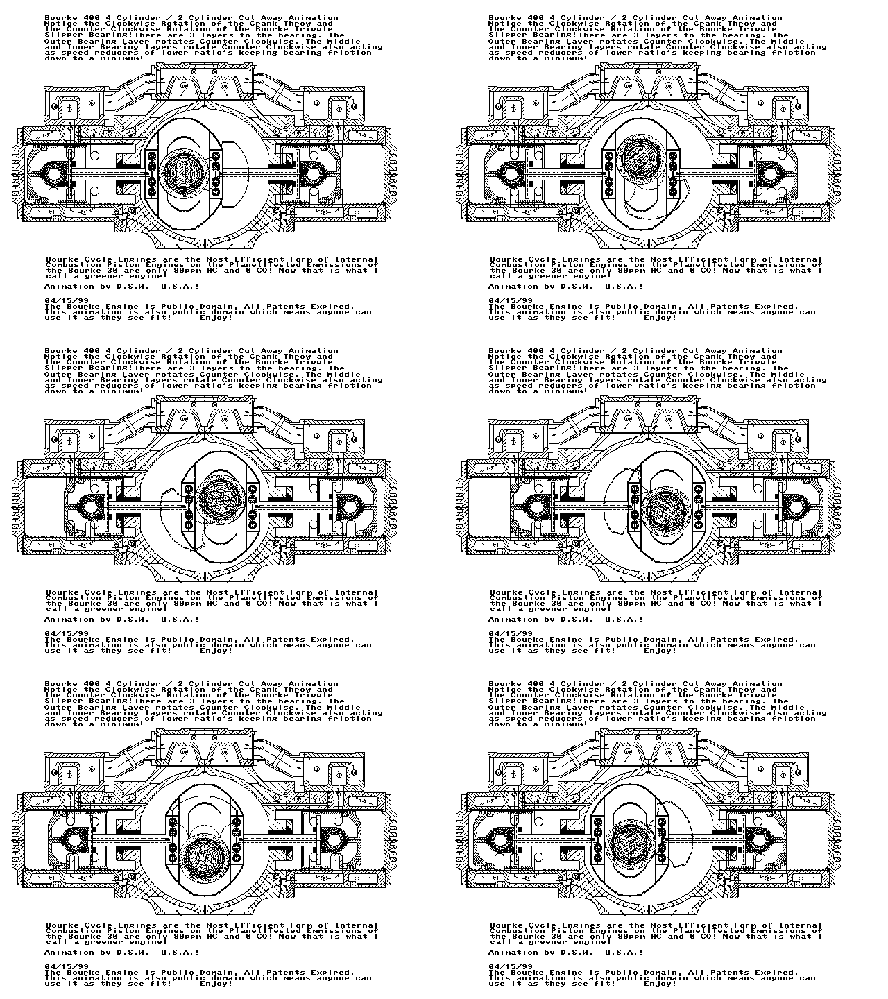
Check out this video clip, you can obviously see how the rods could easily be sucked into a bifilar solenoid coil like in Bob Teal's patents.
Here are a bunch of pics/clips of the Bourke project:
Project Bourke Engine! Now We're Gettin Somewhere!
The Bourke Engine! A Step In The Right Direction!
How The Bourke Engine Works by Bourke-Engine.Com
There are obviously some very capable people here with mechanical ability that could make this style of 2 piston engine for a Bob Teal setup. It could probably be much more mechanically simple as far as the fact goes that there doesn't need to be a combustion chamber, etc... Anyway, that has been what I thought would be the ideal Bob Teal piston setup.
Elias, maybe you can do a torque comparison to this concept compared to a regular piston/rod/crankshaft setup.
This of course isn't a comparison to rotary vs. solenoid, but since both can utilize Bob Teal's concepts, we might as well see what is truly the optimum solenoid/rod/shaft arrangement for maximum torque per input.Leave a comment:
-
Stay With the Experiment
Jetijs,Originally posted by Jetijs View Post
Its an honor to work with you. Hopefully we are building an archive in this forum so that others can duplicate your success.
Please leave the 6 stranded coil on the core and do not change this out yet. We moved on without discovering WHY the magnetic reed switch didn't work. We must stay with what we are doing so that we learn EVERYTHING that is happening and WHY. Then we can decide to either fix it or replace it, but always with KNOWLEDGE GAINED!
The wire isn't melting, so the wire is not the problem.
Please heat sink the transistors.
Also, start looking for some low OHM resistors, between .05 and .01 ohms. In the near future, we are going to need a few points in the circuit where we can measure currents accurately with your scope. Also, please locate a 10,000uf capacitor rated for at least 50 volts. We are going to need that soon as well.
You are doing just fine. Keep up the great work.
PeterLeave a comment:
-
You Are Right
Elias,Originally posted by elias
I apologize for my earlier post. At this point, I don't accept my objection either. I edited my original post and thank you again for running these tests. ANYTHING that increases the mechanical torque in these motors due to geometry improvements instead of extra electrical input is VERY ON TOPIC here.
Thanks again.
PeterLeave a comment:
-
HiOriginally posted by Aaron View Post
Larger rotors require larger stators in my opinion to make use of the pull force more effectively. Actually when the length of the rotor decreases, RPM of the motor increases. The torque may decrease or not decrease, but the overall horsepower will increase, because of using more of the Pull force.
As Peter said it is not exactly about increasing the tangential vectors of the forces on the rotor, but utilizing more of the PULL force.
What I was saying that electromagnets PULL much stronger than SLIDE, which I did not realize before I saw the effect on Naudin's website. But longer the rotor the more it uses the sliding force and less the pulling force. Pistons utilize the pulling force more effectively.
Actually I want to understand which type of motor has the capability to produce more torque: Pistons or Rotors? I will do some calculations and post my results later.
Other geometries which can maximize the utilization of both the pulling force and the sliding force is appreciated. What else can be done to utilize the direct forces of a coil more effectively especially the PULL force?
EliasLeave a comment:
-
Ok, thank you Peter
I get it now with the LED resistor
I will try all this out tomorrow, because it is already late and I have spent all day in my shop at work. You are right, I am acting too fast and should slow down a little bit. I must learn to be more patient. Also thank you for your patience guiding me through all this. Many things I leadned only by actually doing them by myself. I am honored and proud to be your student
Thank you!
JetijsLeave a comment:

Leave a comment: