
Originally posted by wantomake
View Post
-
All mine have an 8mm shaft except the MY1020. I never had to look for other sizes of bearings, so not much help. I will try to look and see if I can find some somewhere. -
if this is actually the setup you are running and the boost module is located where you show a “UPS”’ in the schematic, my first thought was “I have no idea how that would provide ANY extra energy to the setup.” According to this schematic all you are doing is putting the UPS in series with the charge battery so the energy from the primary goes through both. Yes, the battery should charge, but NO additional energy is brought into the circuit because the output of the boost is being “used up” by the load. It is not being sent “through” the load to the charge battery.Originally posted by BroMikey View Post
HoweverI thought about it ALL NIGHT and couldn’t sleep! I realized that since the GROUND on the boost module is a THROUGH connection. (- in is connected to - out) the positive out of the boost module is going through the load and to the - out of the boost module (which is coupled with the - in) and the - in is going to the + of the charge battery. So you are actually running the load between the output of the boost and the positive of the charge battery also, and it is working without the two diodes I recommended, or they exist inside the boost module.
I am not sure you could run it this way with other boost modules, but now that I understand what is going on, I see why it is possible to get the results you are getting. I thought the output to the load was being WASTED in this schematic, so I could NOT understand your positive results. It is NOT wasted. But be aware that it might not work this way with EVERY boost module. They are not all the same circuit, so a missing diode or one in the wrong place could prevent this from happening.
Leave a comment:
-
Turion,Originally posted by Turion View Post
Still searching for ceramic bearings for the motor I have.
MY-1016-B
The front bearing is:
ID 10mms OD 25mm
The back bearing is:
ID 6mm OD 20mm
Been searching for long time daily. Any particular company besides Amazon? Or maybe I have the wrong motor? Lol for sure!!
I've a very good micrometer in the shop and even used my desk mounted magnifying glass with lights.
There's no hurry, but when I'm ready I'll purchase some. Are all the motors different shaft bearing sizes?
Leave a comment:
-
Last picture. Had to stop the charge battery is full again and the run batteries have 40% left in them. Going to bed, nite
Edit add 3WH to the 9WH to cover the idling energy burning over a 5 plus hr run. Each pack only runs 3 hrs max by itself delivering 6 WH

 Last edited by BroMikey; 08-01-2022, 07:13 AM.
Leave a comment:
-
If 100 watts goes THROUGH the primary side of the inverter that is 85% efficient (to the charge battery) the secondary "generates" 85 watts. You only have to "recover" 15 watts of the 100 you put in to get a COP>1. You may be recovering MORE than that, plus your inverter may be better than 85% efficient. The gains have always been there if people would just BUILD it and look. The more efficient the boost module, the higher the gains, because the MORE you recover and the MORE you generate.Last edited by Turion; 08-01-2022, 06:21 AM.Leave a comment:
-
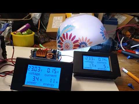
Yes of course. I waited 4 hrs. Here is the rotated packs running again and BTW I am over 18 WH as of 1:00am Each pack only took 5-6wh charging and no more than 6 WH straight discharge yet I have more. It will never go dead like this. See the bowl in the back ground?Originally posted by Turion View Post
I have already burned up going on 10 WH. WTH is going on? I'll be up for days. The run pack is at 22.45v as of 18 WH
Leave a comment:
-
You need to wait and see if battery 3 holds voltage after you quit all your testing and after it has rested, and where your primary pack ends up. Once battery 3 is FULL, you are wasting energy if you keep trying to charge it. If you then rotate your batteries, you should be good to keep it going.Last edited by Turion; 08-01-2022, 05:44 AM.Leave a comment:
-
9.6v and it is tanked. Yes I keep saying X number of ah but I mean WH not AH then yes I say inverter when I mean converter.Originally posted by Turion View Post
The thing is still running and yes I have a bowl over the big light but don't forget all 3 back lights for the watt meter panels plus all 3 watt meter circuits are burning power plus the bright lights and digital readout lights on the inverter plus the inverter internal circuit. That is a bunch and it looks like I may get another 6 WH before I switch? I am having fun Dave thanks. I'll post the circuit.
Oops the charge battery has a cap. Remember these li ion batteries run from 11v-10v the entire run and then bottom out in 3 minutes.
The new run shows over 14WH and the run pack is still 22.65v. That is amazing. I have never seen battery 3 charge right up till today.
 Last edited by BroMikey; 08-01-2022, 05:25 AM.
Leave a comment:
-
What is your circuit for this video? You keep talking about an inverter in the first video. I see what looks like a boost module, but NO inverter, and it sounds like you are running the light off the boost module, so there is still no pulse going to the batteries as far as I can tell. In the second video I see no light, so is it still there? Not knowing exactly what the circuit is makes it hard to know. Anyway, have fun! You always learn something when you start running experiments. Li batteries aren't supposed to be discharged that low, are they? So it will be interesting to see how it responds after that kind of discharge. Started at 9 volts???Last edited by Turion; 08-01-2022, 05:07 AM.Leave a comment:
-
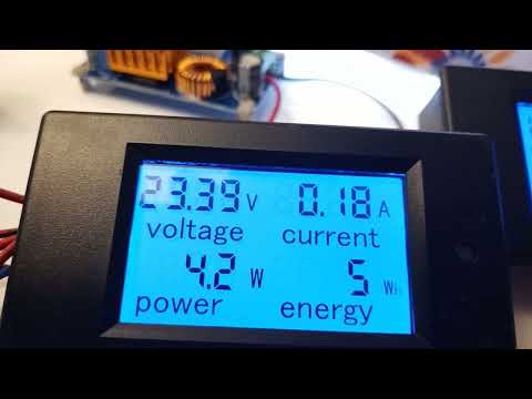
More coming. Cap is 50vdc 2200uf. Four hours later I have started test run 2 due to excess energy still in pack 2. Pack 3 is charged at 12v and pack 2 is over 11v. Battery 1 is dead.
This video is in the middle of the first test run BRB

Leave a comment:
-
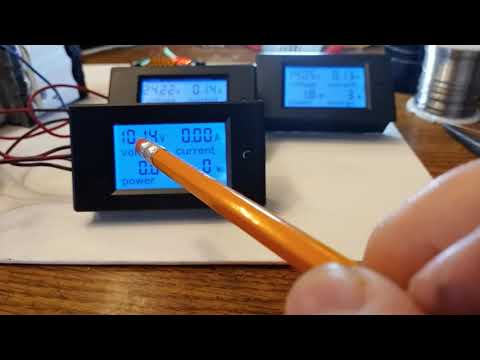
It finished in another video, this is the beginning. I used 11wh from the source batteries, the loads consumed 6 wh and battery 3 recharged using 5wh.
Leave a comment:
-
Here’s why high speed ceramic bearings. 8mm
You can buy a new car for the cost of some of these bearings
Last edited by Turion; 08-01-2022, 02:30 AM.Leave a comment:
-
The BatterySaver model takes the remaining low-voltage output from dead batteries and raises the voltage to a usable level by discharging the remaining energy at a high rate. It does this by operating at a lower voltage than standard voltage regulators, allowing it to extend the life of almost any battery type, capacity and chemistry.
This unique approach avoids expending energy when boosting is not required, as this technology uses low power switching to autonomously engage the boosting circuitry only when necessary. No other boosting method can recover this remaining energy in a dead battery without sacrificing response time or power output, both of which make other methods unusable in most electronic applications.
How does this work? It is essentially rewiring a circuit board that can fit on top of an existing battery or inside the battery casing; It’s small, low-tech, and cheap enough to be retrofitted or built into a device from the get-go, and smart enough to tap into energy stores that regularly go to waste.
After completing four years of prototyping, the team has bootstrapped $100,000, and is exploring licensing offers.
At Udell’s location in the Santa Rosa hills, he shows me a working prototype, about the size of a penny, a strip of wires to connect to a battery terminal. BatterySaver prototypes are small, inexpensive, flexible, and can be attached to terminals or housing, installed on the battery itself, or retrofitted after manufacture.
Gabriella Hasbun
Udell removes a dead battery from a radio, connects the prototype, reinserts, and the machine comes to life.
“We have an electronic solution to a chemical problem,” Bill Seidel, 75, a longtime Udell collaborator with a gray ponytail, tells popular mechanics, Seidel is QVC turned out to be a hit, Developed a US military product, and now serves as Vice President of Marketing for BatterySaver.
Udell says the cost to manufacture is just 12 cents per unit, with retail plans to package two BatterySaver units for 99 cents per package.
https://biz.crast.net/this-91-year-o...to-30-percent/
Last edited by Turion; 07-31-2022, 06:28 PM.Leave a comment:


Leave a comment: