
Three schematics bro posted above.
orion,
look at post 3448. My theory on batteries. Also look at my recent post where I state that a boost module, run between the positives, is a free energy device because you recover some of the input energy in the lower potential side plus you ge the “generated” energy of the module output. The same goes for a buck module. The same goes for a transformer wired to used pulsed DC to mimic AC. Run EVERYTHING on potentials.
-
I've been mostly gone for years and still the argument rages. Without even reading anything but the last couple of posts here; I can say that Turion is mostly or completely correct. "They" say that electrons are transformed into heat or magnetic fields. Total BS!!!
No electrons are harmed or lost.....ever....period!!!!! The only thing lost is potential (Voltage Drop, hello!) which can be recovered and exceeded with great efficiency using an active clamp convertor. If using another lower potential battery to capture the electrons you have to deal with the battery charging limitations.
Because the methods we were taught and that most believe; systems are made to simply throw away those electrons instead of re-use methods that are possible.
Prove me wrong.
OrionLeave a comment:
-
Just to prove I am not a complete ass, here are the issues I see. And remember, we found this stuff out by accident. Things worked and we didn't know WHY. It is hard to teach how to do something correctly when you don't know WHY it is working. We just had "working" setups. Anyway, to get to the three schematics you have just shown.
Pulse charging methods has been developed as one of the fast charging methods for Lithium ion battery. This technique applies the continuous constant current and pulse with certain pulse width until the battery fully charged.
Post 3484
Runs the inverter between the positives NO DEVICE PULSING THE BATTERY. CONSTANT CURRENT ONLY
Runs Boost between the positives NO DEVICE PULSING THE BATTERY. CONSTANT CURRENT ONLY
Post 3487
Output of the boost (which is run between the positives) is run DIRECTLY to the battery without going through a load. WASTE
The motor is run directly between the positives with NO VOLTAGE CONTROL TO ADJUST THE PULSE.
POST 3488
Load run between the positives NO DEVICE PULSING THE BATTERY. CONSTANT CURRENT ONLY
Leave a comment:
-
Yes. Years ago I had the schematic Turion sent me and was able to use two Matt modified motors with two boost converters built the system, then posted on YouTube. Posted the proof of concept here.
So fast forward to fear-demic present and I was encouraged by people around me to find cheaper electricity for them. Solar I answered them. Since my shop has low powered solar and began converting over to lithium batteries.
I can't find my schematic drawings from those times. Therefore I watched Turions video, drew another schematic and used the Carlos Benitez 4 switch battery setup minus Peter L. Lenz free motor. It's the same setup as Turion is using in the video minus the 4 switches. It works now with minimal heat and charges.
I want to add another "resting" bank of batteries as Turion instructed some years ago. But resources and my hard head gets in the way.
I want to use my lithium banks(per Yehu Garcia videos and products) but don't think the BMS on each pack will work in this system. My lithium banks are 24 volt system charging with 24 volt solar setup. But only 2k watts of backup with a ups in emergency times. Really small but good gain of knowledge.Leave a comment:
-
I'm not nervous. I know what will work and what won't. It's your build and your problem. You make fun of me for saying the same thing over and over and over again. And then you post several schematics that leave OUT what I have said over and over and over is necessary for SUCCESS. So good luck. You are going to get exactly what you deserve. But you will get there if you work on it long enough. I did. Wantomake did. Others have also. People who pay attention just get it faster.


Leave a comment:
-
Here is one of my bigger boosters so if I can make these tiny ones work I can get bigger batteries
flyer.thenetteam.net/3batterygen/DConvert1.jpg
flyer.thenetteam.net/3batterygen/DConvert2.jpg
flyer.thenetteam.net/3batterygen/DConvert3.jpg
flyer.thenetteam.net/3batterygen/DConvert4.jpg
..........

Leave a comment:
-
I'll probably use this one by substituting the inverter for a converter circuit. No luck needed. Dave is nervous again

Leave a comment:
-
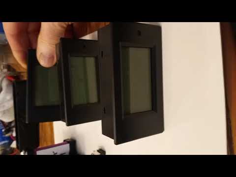
Here are the stat's on my watt meters. The picture I posted is wrong I will only be using a single boost converter that will be powered up split positive arrangement. The second boost could be used to keep me from switching batteries round. This diagram was produced from coaching from you Dave, years back. Are you taking it back?
I was looking to see how much these watt meter eat at the circuit. I will assume 25-50ma- 1. Electical parameter measurement function(Voltage, current,active power, energy)
2. Voltage alarm function(over voltage alarm threshold, backlight and voltage flashing to alarm)
3. The reset function of energy key.
4. Store date when power off.
5. Large-screen LCD (display voltage, current, active power, energy at the same time)
6. Backlight function. - Display interface
Display interface is large-screen LCD (display Voltage, current, power, energy parameters at the same time) - Display format:
1. Power: test range: 0-2KW
Within 1kw, the display format is 0.0-999.9W;
1kw and about, the display format is 1000-2000w.
2. Energy: test range: 0-9999kwh
Within 10kwh, the display format is 0-9999wh;
10kw and about, the display format is 10-9999kwh.
3. Voltage: test range: 6.5-100v
Display format: 6.50-99.9v
4. Current: test range: 0-20A
Display format: 0.00-20.00 - Precautions:
1. This module is suitable for indoor, please do not use outdoor.
2. Applied load should not exceed the rated voltage, current.
3. Wiring order can't be wrong. - Specifications:
Type: PAEM-031
Working voltage: 6.5-100VDC
Test voltage:6.5-100VDC
Rated power: 20A/200W
Meaurement accuracy: 1.0 grade
Size: 89.6*49.6*24.4mm(Length*Wide*High)
LCD screen: 51*30mm(Length*Wide)
Color: Black
Leave a comment:
- 1. Electical parameter measurement function(Voltage, current,active power, energy)
-
Here is my very basic free energy device without the motor as a load. I will burn LED lights

Leave a comment:


Leave a comment: