
To make it simple, think of it this way. There are five rows of copper strips. Spaced evenly around the pipe. With five batteries you need five rows. To use four batteries you need four rows. For 6 batteries, six rows.
The length of the strips depends on the diameter of the pipe. You want enough space between the rows that your "contactor" cannot touch two rows at the same time. As long as there is ENOUGH space, a little extra doesn't matter. There are 12 strips in each row. That's one for each terminal of each of your five batteries plus one at each end to connect to the two sides of the load.
Because you have only 4 batteries (8 connecting points) and 2 load connecting points NECESSARY in each row, two of the strips in each row WILL NOT BE USED, so I just leave them OFF. That means one battery is always disconnected. By changing what the wires inside the pipe connect to, you change which battery is disconnected. You also change which two are in series and which two are in parallel. That's all the wires do. The two load connecting points on the end of each row connect to the + of the two batteries in series, and the + of the two batteries in parallel. The other wires connect the two batteries in series and the two batteries in parallel. In each row, there are different connections that rotate all five batteries through those four positions plus one resting position.
You can fill in between the strips of copper with little pieces of plastic and epoxy and sand it down so there are no "bumps" as the contactors (brushes) move around in a circle. I don't think I would use brushes because that spring uses more force than I would like. If you remember the old slot cars that had contacts on the bottom to electrically connect them to the track, I use something that looks a lot like that. Its weight makes the connection, and you can even glue on a washer or a nut if you don't like how the connection is made.
EDIT: You could rotate this thing constantly, or every 20 minutes or so. I wouldn't run it at 1,000 rpm, but you can have it constantly rotating. How fast you spin it will kind of depend on how well the LOAD runs, since you are constantly breaking the contact with the load. Now a cap across the load will definitely assist in keeping constant current and voltage, but I would speed it up enough to keep the load running. The bigger the cap, the slower you can run it. But there is NO NEED to rotate it more than once every 20 minutes.
-
Thanks Dave, you are right I missed that video and now I get the whole physical layout with the wires inside plus keeping sections of stripes on the tube. I watched some videos where wood was used.
Is it better to have it machined so the brushes don't jump so bad or are we talking 100 rpm? Either way glad you are a fluent typist, it is so clear now except for the chartLast edited by BroMikey; 09-02-2022, 07:29 PM.Leave a comment:
-
GLUE. like I SAID in the video.Originally posted by BroMikey View Post
You need about 4" minimum around the outside. That's a pretty BIG dowel, and you couldn't put the wires "inside because it is not hollow. That's why I SAID use PVC pipe with caps on both ends. I NEVER said wooden dowel. Perhaps you need to watch the video again and listen. I made an even MORE detailed explanation in the first video than I did when I remade it.Originally posted by BroMikey View Post
Glue some foil on a toilet paper roll. Incomplete info as usual. AFTer I build it you will simply say "not like that"[/QUOTE]
Did I say toilet paper roll?
No. I CLEARLY said a piece of 4" or 6" diameter PVC pipe with END CAPS. Last time I used 6" PVC pipe and I have both 6" and 4" but this time I am building with 4" diameter because the end caps for the 6" pipe are ridiculous in price now.
I CLEARLY said drill a hole in the center of both end caps to put a shaft through and attach the cap to both the shaft and the pipe. This couldn't be more simple.
Yes, I will, because YOU don't pay attention when you watch the video in the first place, or you wouldn't ask questions about "wooden dowels" or bring up toilet paper rolls.Originally posted by BroMikey View Post
You can drill a hole through the center of both end caps to put a piece of all thread through to act as a shaft. That is what I did. Then I put a nut on both sides of ONE of the end caps and tightened it up with all-thread on the threads BEFORE I glued that cap onto the pipe. I made SURE I had enough all thread sticking out to go all the way through the pipe and out the cap on the other side. Now when I turned the all thread, the whole pipe turned. The other end cap I did NOT glue on to give me access to the wires. This time I may just glue the PVC on a shaft. WHY? because all-thread does not fit tightly in my bearings. I use skate board bearings, and you can find shafts that will fit them at Lowes or Home depot. The caps can just be GLUED onto the shaft because there is no torque or resistance (to speak of) that would break the cap free of the shaft once they are glued together.
I CLEARLY said the wires would all be INSIDE the pipe. How you attach the strips on the outside is up to you. I simply glue them on with epoxy. BUT, between the pieces of copper I glue little pieces of plastic that are the SAME HEIGHT as my copper. What I actually did is cut my pieces of copper about 3/4" longer than I wanted them, then bend 3/8 at each end at a 90 degree angle. I drilled a small hole in this bent piece to put my wire into and solder it in place. I drilled holes in the EXACT place that I want the copper to go and the bent end with the wire soldered on ends fit into the holes and is epoxied in place. I drill both holes just a bit bigger than the copper because I want to be able to adjust it so that all the pieces align, and so that the wire will feed in easily.
With transistors, you have to make sure that the ones on each side turn on at EXACTLY the same time, which is why you need optocouplers. With this setup that is not critical. I can put the glue on one end of the copper that is going into the hole, then put my square across the pipe and push the pieces of copper against the square. I glue one end in place (the end with the wire) and let it dry before doing anything else. They make a super glue that is more like a gel than a liquid, and that is what I used so it would fill in the hole around the copper. without dripping inside the tube too much. That's as detailed as I am going to get. Probably NOBODY will use the same size copper as I use, so every build will be different.
Here is the copper I am using: https://www.amazon.com/dp/B00HHCT46A...roduct_details
It's a little more than 1/8 of an inch wide. That means I really only need enough PVC pipe to hold the two end caps, because when you push them together, you have enough length to put 12 of the 1/8 inch strips with space between them. This is NOT the copper I used last time, but I have no more of that. It was 1/2" wide strip, but this will make contact too. That's all I need.Last edited by Turion; 09-02-2022, 05:48 AM.Leave a comment:
-
$100 bucks and learn to collect the back spike today, not in 5 years, See Bob Teal magnipulsion
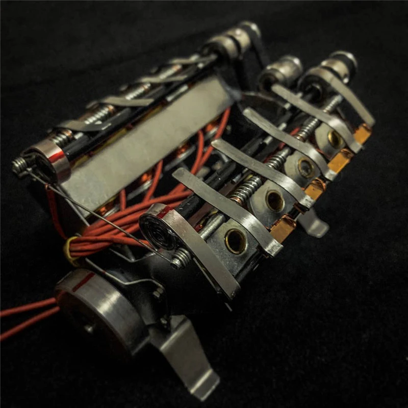
See video switching 8 solenoid pistons on aliexpress
https://www.aliexpress.com/item/2255...xx__1662093514
https://ae01.alicdn.com/kf/Ha63121f3b79845eca553b89d6c924f8aq/V8-Electromagnetic-Generator-Model-High-Speed-Generator-Model-Electric-Start.jpg_Q90.jpg_.webp
 Last edited by BroMikey; 09-02-2022, 04:49 AM.
Leave a comment:
-
Yeah it was a joke, why lie on meOriginally posted by Turion View Post you dog, I just can't find the time with everything going on, my cement, you understand maybe this weekend
That is a cool circuit. On the mechanical version, do you make grooves to glue your copper stripes? Or how are they attached even after they are all chopped in segments? What approx Dia of wooden dowel and is the distance around the circle mean anything? How does the duration change?
Glue some foil on a toilet paper roll. Incomplete info as usual. AFTer I build it you will simply say "not like that"
EDIT I built a $1000 plus ozone machine and hooked to pure oxygen, it cleans every smell you might have like smokeLast edited by BroMikey; 09-02-2022, 03:09 AM.Leave a comment:
-
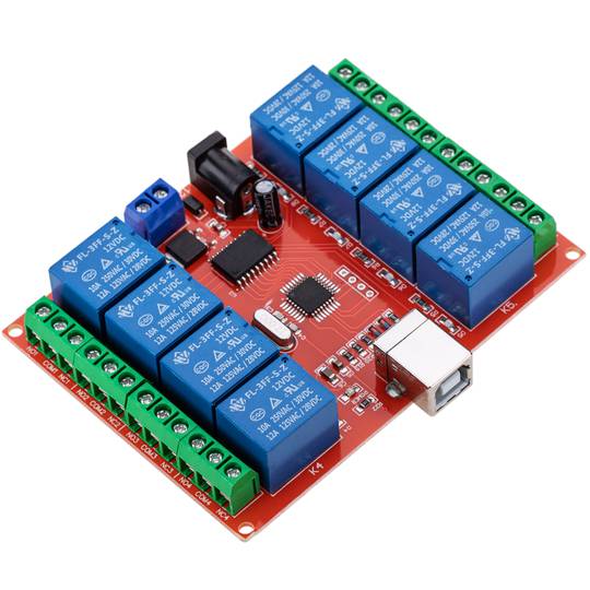
If you are building an electronic version of the Tesla Switch, one thing John B said is ALL the transistors on one side and ALL the transistors on the other side must turn on at the same time. He recommended opticouplers to control that. Now I haven't found an "off the shelf" circuit board that will do that with transistors, but here's something for those who have some extra cash lying around and have a computer on their bench.
Leave a comment:
-
The Turion picture shown here is the electronic version I'm setting up now. I don't have a suitable transformer therefore I'm building my own. I too have budget of "0" since retirement . Lol!!Originally posted by Turion View Post
Turion did the MJL21194 transistors work out ok? I can't know they do until the transformer is finished. The transformer is a larger beast sized one but will see.Leave a comment:
-
I made a pretty serious mistake in what I said in the following video, and I don't have time tonight to redo it. The piece of metal on each end that the load connects to must go all the way around, but it must have the BREAKS in it also, or it will short out the whole thing.
Here is the video. THIS IS AN UPDATED EDITED VIDEO TO CORRECT THE MISTAKE I MADE
Last edited by Turion; 09-01-2022, 06:28 AM.Leave a comment:
-
Talk about handed it to me. This is a brain teaser, like a crossword puzzle. My weakness. you hate math, I hate crosswords. 
 Still thinking. Well it is less boring than solar.
$13 is going to break the kitty? Sounds like me.
PS I'll bet smoke damage sucks. Use an OZONE MACHINE
EDIT I am not sure how to physically arrange the rotor. My bad.
Last edited by BroMikey; 09-01-2022, 02:20 AM.Leave a comment:
-
On the bottom of this schematic are five batteries, but only FOUR are connected at the same time.
Above the row of batteries are the five sections that would be on the rotor.
If you look at the first section, if the batteries were connected directly to it, the two batteries on the left would be put in series. The two batteries on the right would be in parallel, and the series batteries would be placed in parallel with the batteries in parallel, and the load would be between the positives.
Attached FilesLeave a comment:
-
-
The proof I WANTED SO BAD? Is that a joke? YOU are the one who insisted you wouldn't build it without proof!Originally posted by BroMikey View Post
I've built MULTIPLE versions of the Tesla Switch, and have one on my bench RIGHT NOW that I am playing with.
I am also building the mechanical one turned by a motor just to prove the point. I have to wait until midnight tonight to order the parts because I am on a monthly budget for this kind of stuff, and I ran over budget last month by $13.00 so not going to push my luck.
I use this to make both the contacts on the roller and the connectors, as it is stiff enough that it can be bent into the proper shape.
SInce these strips are a little over 1/8 of an inch wide, and you only need 12 on the rotor, it doesn't have to be a very long rotor. 4" long piece of 4" pipe with caps on both ends wide is plenty. Leaves you lots of space between strips.
Leave a comment:
-
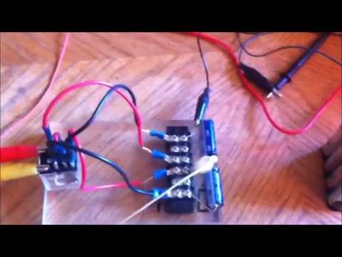
there is your proof you wanted so bad Dave and it stays charged without costing much 1/4 watt and you got 10-20watt. 1 panel gives 50watts knocks them both out twice, for peanuts. hook up a cap pulser, sssg and run panels like you do. Some need more than an experiment they need power like you get from panels. Why not do a video using all your experience showing the best way to solar charge batts. mppt? batts and panels? no kiddin
 Last edited by BroMikey; 08-31-2022, 06:38 AM.
Leave a comment:



Leave a comment: