This forum is preserved as a permanent archive. The community continues at eMedia Press.

Announcement

Collapse
No announcement yet.

Interesting Motor

Collapse
X
 
  • Filter
  • Time
  • Show
Clear All
new posts

  • Interesting Motor

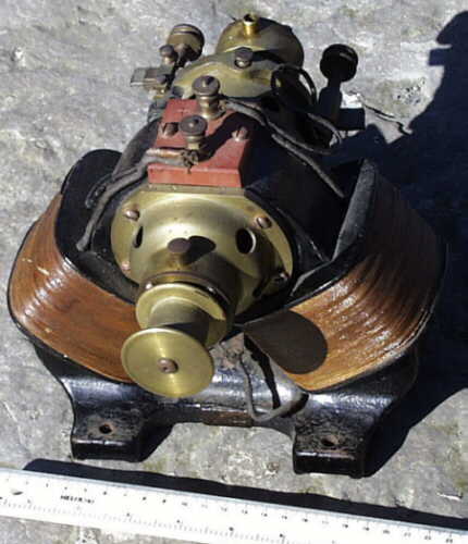
    I came across this picture on an antique website, I think it is some kind of motor but it could be a generator. I wondered if anyone knows anything about it?

    I find the geometry quite interesting as I have built motors with a similar looking geometry that have unusual characteristics.
    Attached Files
  • #2
    I believe this to be a universal motor so the pole faces cover almost half the armature at each side but could very easily be modified.

    Comment


    • #3
      Most Probably DC Series Motor

      Dear mbrownn,

      I have looked at the motor image you posted. There are a number of features present that I think would not be found in a Universal Motor, as you suggest.

      The first being that the base frame also seems to be the magnetic keeper between the stator coils. From the appearance, this frame looks like cast iron painted black. That would provide pretty bad eddy current losses for a varying field. The stator coils look like they are wound with a moderate sized wire covered with a plastic film of some kind.

      So, while the coils could handle AC or DC, the lack of laminations in the stator core suggests DC operation.

      The two main terminals on the Red Block on top appear to have wires that go to both the stator windings and at least one brush for the commutator on the back side. This looks like a series connection between the stator field and the armature. There is definitely a wire leading to the brush on the right. The wire from the terminal block to the brush on the left is ambiguous, but a wire definitely leaves the terminal block and goes somewhere. So, if the power supply was connected to the Left Brush and the other wire leaving the terminal block, that would produce a series connection.

      DC Shunt Motor operation seems unlikely, primarily because the wire diameter is the same going to the stator coils as going to the armature brushes. The large pulley on the front suggests significant torque available from this motor which would require high currents running in the armature. Since the wire size is the same for the brushes and the stator coils, series connection seems the most likely, with a moderate DC voltage (like 50 to 100 VDC) necessary for operation.

      That's what it looks like to me.

      That, plus the oiling features for the bearings and cleaned up condition, it looks like a sweet machine, probably built before 1940. It may still have been in good running condition when the picture was taken.

      Best regards,
      Peter
      Last edited by Peter Lindemann; 09-09-2014, 04:22 PM.
      Peter Lindemann, D.Sc.

      Open System Thermodynamics Perpetual Motion Reality Electric Motor Secrets
      Battery Secrets Magnet Secrets Tesla's Radiant Energy Real Rain Making
      Bedini SG: The Complete Handbook Series Magnetic Energy Secrets

      Comment


      • #4

        Comment


        • #5
          @mbrownn
          I love old stuff and it would seem to me in our modern age we have lost what I would call...character. Those old motors define an age when much was new and many of the hard and fast rules were yet to be written.

          I too have explored the benefits of linear motor action however some general rules still apply. It is not unlike a modern induction motor in that the magnetic field is coupled between two magnetic sources thus if the stator field change is greater it is a motor action and if it is lesser it is a generator action. It may be either the coil moving with it's inherent magnetic field or the magnet field expanding/contracting however the rate of change of the field is what matters most.

          I believe it may have been Faraday who said it does not matter how the field changes(physical motion or expansion/contraction) only that it does. Thus we are left with the notion that it may be up to us to imagine how we might cause a field change in a more efficient way. In any case I find something very attractive about oscillating motions and prefer them over spinning motion. It would seem to me oscillation is the universal motion and spin an after effect. Interesting stuff

          AC

          Comment


          • #6
            Originally posted by Allcanadian View Post
            @mbrownn
            It is not unlike a modern induction motor in that the magnetic field is coupled between two magnetic sources thus if the stator field change is greater it is a motor action and if it is lesser it is a generator action. It may be either the coil moving with it's inherent magnetic field or the magnet field expanding/contracting however the rate of change of the field is what matters most.

            I believe it may have been Faraday who said it does not matter how the field changes(physical motion or expansion/contraction) only that it does. Thus we are left with the notion that it may be up to us to imagine how we might cause a field change in a more efficient way. In any case I find something very attractive about oscillating motions and prefer them over spinning motion. It would seem to me oscillation is the universal motion and spin an after effect. Interesting stuff
            Correct, but in the case I put above we would be using DC and there would be no change in the intensity of the flux. I have put AC into my motor and got some very interesting results, but we will deal with the DC for now.

            Used on DC we have a motor generator with the usable torque and a DC output from a single input. No its not enough to self run even if we put a generator on the output shaft, but we have narrowed the gap when compared to a standard motor. If we had a donor motor with an efficiency above 50% before we modify it, we could be very close . I have not tried replacing the powered field coil with a permanent magnet, but it would be interesting to measure the results of such an experiment and I encourage people to try it.

            Remember that our generated output has to be less than our input but we also have the mechanical output available too. Normally in a universal type motor, there is BEMF in both field coils and both field coils are contributing to the torque, here the BEMF is in the generator coil and so is an output. the torque is also occurring in the generator coil.

            There is no reason why the output current could not be run through the armature before going to the load as the armature typically has a very low resistance, this additional current in the armature adds to the torque and so compensates for the load being drawn to some extent The output torque does not drop as much as you would expect and in some specific cases does increase, but for different reasons. Think about this one because there are further implications.
            Much about what I am proposing is counter intuitive.

            Comment


            • #7
              As motors like the one in the picture are no longer available, we have to choose a different donor motor. Any four pole motor similar in design to a starter motor would be good, preferably the armature has an even number of slots. This is because I propose a rewind of the armature. A standard lap wound armature with an odd number of slots can be used to achieve what I have mentioned above but has some characteristics that would work against us.

              I have used starter motors and highly modified universal motors but I have been told that starter generators like you find on golf carts are simpler to work with. These are not available where I live.

              The first step is to remove two adjacent coils and their pole pieces (I call them shoes), wire the armature and one of the field coils up in attraction by having the brushes in line with the powered field coil (this may vary slightly depending upon the winding of the armature). The motor may or may not turn at this stage, it just depends upon the shoe of the unused/generator coil. Adjust the brushes until the motor turns in a direction from the unused shoe towards the powered field coil.

              The most common reason I and others have found for not being able to get it to run successfully is if the brushes are too wide thus the motor reaches magnetic lock before disconnecting with the correct segment on the commutator. Another reason can be the shape and size of the generator shoe.

              Watch out for the current draw, it is likely to be high. I used 3v on a motor designed to run on 12v.

              Theoretically a permanent magnet could be used as the powered field coil although this is something I have not tried. If you are using a permanent magnet four pole motor, you will have to improvise making the shoe and generator coil.

              This is an attraction motor, so the shoe of the generator coil will have to be in position before it will turn to allow a return path for the flux. It is the angle of the flux passing through this shoe that causes the armature to turn, and if it were not in place the motor would just sit magnetically locked in position.
              Last edited by mbrownn; 09-14-2014, 03:27 PM. Reason: correcting an error

              Comment


              • #8
                Simple DC motor

                What I see is a simple DC motor where the brushes apply current alternating between the two coils. Only one coil is powered at any one time. The rotor consists of a soft iron bar that aligns first with the one coil and then with the other. This motor will run in either direction and needs to be unloaded and given a push in the desired direction before applying power and a load. This motor is not practical in today's environment. We expect much more of any modern prime mover.
                There is a reason why science has been successful and technology is widespread. Don't be afraid to do the math and apply the laws of physics.

                Comment


                • #9
                  Originally posted by wayne.ct View Post
                  What I see is a simple DC motor where the brushes apply current alternating between the two coils. Only one coil is powered at any one time. The rotor consists of a soft iron bar that aligns first with the one coil and then with the other. This motor will run in either direction and needs to be unloaded and given a push in the desired direction before applying power and a load. This motor is not practical in today's environment. We expect much more of any modern prime mover.

                  Comment


                  • #10
                    I will try to help you understand what is going on. This is how I see it, if you disagree then feel free to say so, then we can work out between us what is correct in a civilised manor.

                    We are using Direct Current

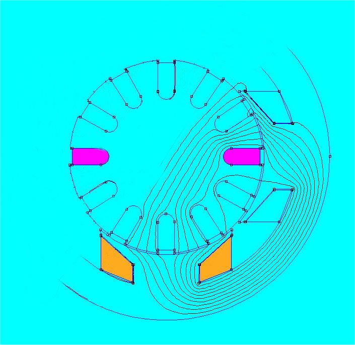
                    Both pictures use a simplified armature winding.

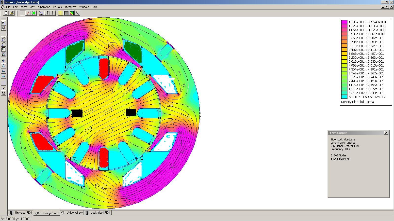
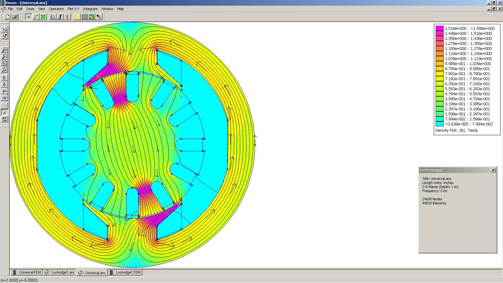
                    The second picture is set up in attraction, a universal motor is both attraction and repulsion depending where you look on the armature.

                    The first picture is a universal type motor showing the lines of flux and the areas of greatest concentration of flux. These areas of greatest concentration are also the areas where the flux moves and varies in concentration the most, this is where and why BEMF is produced.

                    The second picture is my concept. note that the powered field coil has little or no change in the concentration of flux, thus little BEMF. The armature does have BEMF just as in the universal motor as will the unpowered coil (generator). Because of this we do not need to apply as much voltage to obtain the same current in the windings.

                    Another reason for the dramatic reduction in BEMF is that the armature windings tend to be fewer turns than the field windings in these types of motor. I have only bothered to count one motor as I stripped it and the ratio was approximately 3 to 1. This was backed up by achieving similar speeds with my motor at 3 to 4 volts as would have been obtained with 12v on the donor motor. Hence I say little or no BEMF in the field coil.

                    As the field strength is proportional to the current flow then the torque will be the same. ie same mechanical power for less input power and we get a gain in efficiency. Not 100% accurate but generally it is true.

                    It is the bunching of the flux combined with how the flux prefers a straighter path that causes the torque, this is how we can get torque without repulsion. In a universal motor we get both repulsion and bunching of flux so the torque should be higher in a universal motor than in my design and this does seem to be the case, but not by as big a margin as I expected. I think the lap winding compromise is the cause of this. We need more replications to confirm this.

                    The performance characteristics under load was slightly worse than a standard universal motor, ie the speed dropped quicker under load than a standard motor but our input power was a lot less. I would say we had 1/2 of the power out for 1/3rd of the input but could not accurately measure it.

                    If I had put a lap wound armature in the simulation you would see a lot more complexity and many more areas where BEMF are being generated, in fact it is so complex that is much harder to see how the torque is produced. The truth is the sum of the positive torque areas is greater than the sum of the negative torque areas so we still have good torque but not as much as we could have. A lap wound armature is a compromise. I wont go further into this because I want people to understand the concept I propose and not get confused. A simple armature winding works best in this case even if it does arc a lot, this can be eliminated by other means.
                    Attached Files

                    Comment


                    • #11
                      As far as the brushes are concerned, it is difficult to generalise as there are so many different brushes and brush holders used on motors, and few are adjustable so you may have to be quite ingenious to make them so, but here is some general advice.

                      Carbon brushes tend to have quite a high resistance when compared to the armatures on these motors, I have measured some as high as 8 ohms while the armature itself was a very small fraction of an ohm. If you are going to replace your brushes then consider their resistance as you want it as low as possible. I like the idea of brushes similar to the ones in the picture I first posted as I understand their resistance was very low.

                      Generally speaking the contact force of the brushes with the commutator is made quite high which does introduce some friction, usually you can reduce this contact force considerably with little effect on the motor. Reducing the brush width increases the contact force on the commutator so we can reduce the brush spring force and still maintain good conductivity while lowering friction.

                      Normally a brush is wider than one segment of the commutator, this means that three segments can be in contact with the brush at the same time. this has several disadvantages but I will concentrate on three for now.

                      The first problem is the sweep of the powered coil across the generator shoe. If this sweep angle is too great, the motor will reach a point where it will want to reverse its rotation resulting in the armature stopping rotation while still connected to the supply. Obviously this will result in an armature burn out. Thinning out the brushes can help here to reduce the angle that the powered armature coil sweeps across the generator face. I cannot mention this without mentioning the commutator, some motors have the same number of commutator bars as slots on the armature, some have double that number. I found that having double the number was better to get the right sweep angle.

                      The second problem is having three segments powered at the same time introduces transformer interactions between the armature coils as well as coil shorting. This all effects the inductance of the armature and introduces a lot of transients going in both directions, narrowing the brushes to one segment width or less simplifies this condition especially if your using a lap wound armature.

                      Very high voltages can build up in the armature causing brush and commutator damage at an alarming rate as we have no compensation coil to minimise this. I will go into how we remove this power with a second set of brushes at a later date but some of you will be able to figure it out. Reducing the brush width has a positive effect here as far as we are concerned especially with a simple rewound armature. More on this later.

                      Obviously choosing a donor motor with brush carriers that can easily be modified is better. Again some of the Delco starter generators look a better candidate than the starter motors that I used.

                      Brush timing and sweep angle are very important in getting good performance out of this design.

                      Comment


                      • #12
                        When you have built this motor to this stage, it would be good to get some figures on it to add to what we already have. You will need to run at a lower voltage to prevent burning out the coils.

                        Assuming you run at the same amps as the unloaded donor motor, what is the input voltage?
                        what is the input current?
                        What is the output voltage from the generator coil?
                        What is the speed of the motor?

                        Now you will need to load the generator with a relatively low impedance load such as a lamp. you may need to experiment with different lamps to get full brightness.

                        What is the input voltage?
                        what is the input current?
                        What is the output voltage from the generator coil?
                        What is the output current from the generator coil?
                        What is the speed of the motor?

                        Now repeat the test with the output passing through a diode and through the armature or entire motor.

                        What is the input voltage?
                        what is the input current?
                        What is the output voltage from the generator coil after the motor?
                        What is the output current from the generator coil after the motor?
                        What is the speed of the motor?

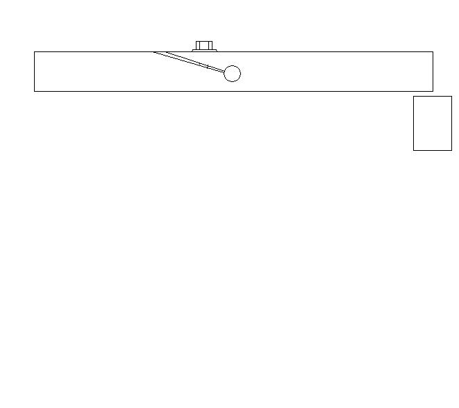
                        Now the tests can be repeated with a mechanical load added, so you will need to make a basic torque measuring device, see picture.

                        This is made from a hard wood and a set of weighing scales. for foot pounds cut the wood to 2 feet in length so you have a 1 foot radius and for kgm cut 2 meters in length. the reason why we have the wood 2 units in length is so that the weight of the wood either side of the shaft is in balance.

                        Slowly tighten the screw until the motor measures the rated current draw for the donor motor.

                        Your output voltage will be lower because of the reduced speed, so you may need a new set of lamps.

                        What is the input voltage?
                        What is the input current?
                        What is the output voltage from the generator coil after the motor?
                        What is the output current from the generator coil after the motor?
                        What is the torque and speed?

                        You will notice that your new motor is drawing significantly less power for the same amps, but your output power is lower too Has there been an improvement in efficiency mechanically?
                        What's the efficiency when you include the electrical output?

                        At this stage you will be well aware of the arcing at the brushes, If you place a scope on the input and the output you will also see spikes in voltage so the next step will be curing that problem and this is also a part of the efficiency improvements.
                        Attached Files

                        Comment


                        • #13

                          Comment


                          • #14
                            Efficiency improvement 3

                            Im sure you are all concerned at the arcing at the brushes so now is the time to address that.

                            Because of the way using a commutator rapidly and abruptly switches on and off the coils in the armature we get inductive kickback and transients in the armature coils, if we are using a standard lap wound armature, these currents are usually dissipated in the coils as they are wired in a loop, but the voltage in the armature rises causing arcing and heat is produced in the coils. This is normally minimized by having a compensation coil. In a universal motor this is the second field coil that is wired in series with the first field coil. Via transformer actions these spikes are transmitted to the field coil. We don't have such a coil fitted, and as we have changed the geometry of the motor, it will not work effectively.

                            The alternative I propose is a second set of brushes that follow the brushes powering the motor. They must be set to contact the commutator segment just as the power brushes disconnect. This way the spikes can pass to a second circuit away from the motor. We could just short these brushes out but to me that is a waste of energy, so I suggest we capture that energy in a capacitor via a diode.

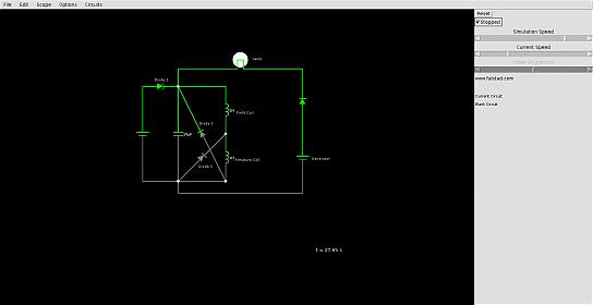
                            To make practical use of this energy we could use it as an output, but I suggest we use it to reduce the input. This is done by placing the capacitor across the source supply, but separating it from the source with a second diode. A third diode will be required to prevent a short circuit. Your circuit will look something like the picture but you will need the values of the components to match your device.

                            The recovery is small with a lap wound armature and may only be a few percent, but worth the effort.

                            If this effects your motor performance it is because the sweep angle of your armature is now two coils of the armature, so you need to keep your eye on that.

                            To be continued....
                            Attached Files

                            Comment


                            • #15
                              Efficiency improvement 4

                              Efficiency improvement 4 gives a dramatic improvement in both mechanical and generated output. You may have been wondering about the second half of the case, and why I did not do anything with it until now. It is because I wanted you to understand the concept of building a low BEMF motor.

                              All we have to do is put the coils in the second half of the case, but there is a problem. If we do this we get a magnetic short circuit and the motor fails to turn, so before this we have to slot the case longitudinally (along the axis) separating it into two magnetic circuits (see picture). Some of you may have seen a device with this feature before These slots need to be about 10mm wide and as long as you can get without the case deforming under load. Better still cut it completely in half and then braze it back together leaving the 10mm wide slots. This is assuming that the front and rear caps are non magnetic and will not cause the magnetic short.

                              Wire the field coil opposite our original power field coil in series and in attraction, the extra resistance will cause a very small drop in input power but the extra generator pole will almost double torque and generator outputs as well as BEMF in the armature.

                              The outputs of the two generator coils can be wired in series or parallel, either one or both being fed through the motor depending on your requirements. One coil could be solely for compensating the load on the armature i.e passed through the armature/motor and shorted on itself, with the other powering an external load.

                              It will run on AC but in this case we cannot have the capacitor across the source as the phasing of the recovery is wrong. There are advantages and disadvantages to AC use which I will cover in another thread at a later date.

                              By passing the generator current through the armature, we can also use this as a normal self exciting DC generator and not power the field coils. All we have to do is crank it.
                              Attached Files

                              Comment

                              Working...
                              X