If this is your first visit, be sure to
check out the FAQ by clicking the
link above. You may have to register
before you can post: click the register link above to proceed. To start viewing messages,
select the forum that you want to visit from the selection below.
Thanks Aaron. I will build it so that the bearing where the input shaft is coupled to the flat plate can either run free or be locked this way it will be easy to figure out which way works best.
I understand what you are saying about fixing shaft to the square plate, however please keep in mind what I am trying to say because the upper shaft is allowed to orbit it can let centrifugal force do the work because it is following the larger orbit centrifugal force wants to take this is why the input shaft does not have to do the work. These are just my thoughts and I will build it to see if I am right. Thanks.
I also show how I disconnect the translation coupler from the lower shaft.
It was almost 2 years ago when Peter Lindemann actually pointed it out to me that it looked like the input lever was moving around.
If you lock the lever to the square plate, then you make the input to the upper part of the lever directly proportional to the movement of that plate and that is exactly what we need to avoid.
By fixing the Input shaft solid to the square plate that the first wait is attached to, spinning the shaft will cause the wait to spin like putting it in a drill. Allowing the input shaft to orbit it can follow the out of balance effect caused by the wait, this will allow the centrifugal force to do the tipping of the lower shaft and not the torque put into the upper shaft to spin the upper wait. It is very clear to me that this machine uses centrifugal force to harvest gravity by using them against each other. I hope you can see what I'm getting at. Thanks.
First let me thank you for starting this thread
I do not want to contradict what you are saying about the back-and-forth motion and the whip effect It would have, but I believe it is moving in a full orbit if you look very closely at it. The way I see this machine operating is that the first wait is like an out of balance wheel this allows the Machine to harvest centrifugal force to do the work of tipping the lower shaft thus putting the lower weight in a state of being constantly lifted on a tilted plain so it will move to the new lowest point in its axis. Without the upper wait we would have to do all of the work to tip the lower shaft in relation to this direction of travel, but with the wait centrifugal force does the work instead. I am not saying this to contradict anyone, it is just the way I see it working I hope this helps.
Take a closer look and I think you will see that the input shaft is spinning in the x/y axis as well as orbiting. I looked at it very close this morning with the video expanded at that point and it was very clear to me that the shaft is rotating. Yes I am talking about the upper input shaft. If you look at the input shaft right where it enters into the x/y axis from the top you will see some marks on the shaft spin by as it rotates.
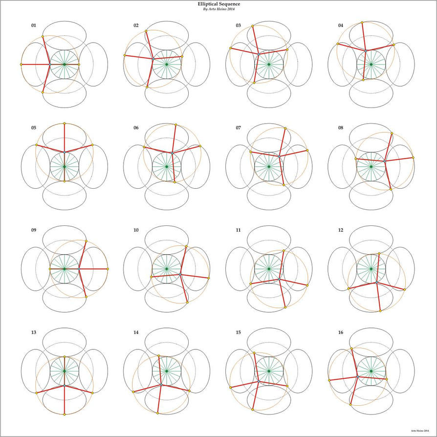
It is rotating but not spinning on it's own axis. And just like the paper coupler demo I showed, the upper part of the input lever is elliptical because the center that it is moving around is moving back and forth. It is the identical concept as the translation coupler.
Are you talking about the top of the input lever rod?
Take a closer look and I think you will see that the input shaft is spinning in the x/y axis as well as orbiting. I looked at it very close this morning with the video expanded at that point and it was very clear to me that the shaft is rotating. Yes I am talking about the upper input shaft. If you look at the input shaft right where it enters into the x/y axis from the top you will see some marks on the shaft spin by as it rotates.
If you look real close the top shafts are also spinning this means that they are fixed to the top pulley. The bottom end of the top shaft is fixed into the square plate that it drives with a set screw, so the X/Y pivot must work the same as a universal joint with a rod and bearing going through the center of it. I hope this helps.
Are you talking about the top of the input lever rod?
I did mention they are going in a type of circular motion, but didn't give details.
If you look at my explanation of the paper mechanism where the "back and forth" motion gets the coupler to whip around, it is nearly a straight line back and forth but with a bit of height to it. If it is 10 units long, at the center it is about 1 unit high. The mechanism works with straight back and forth but is better with the ellipse. The cause of the ellipse is right there on the video.
I need to do another final vid to tie up a few loose ends and I'll do a paper demonstration of the upper input lever mechanism. I'll also show the purpose of the copper tube on the lower shaft. That copper tube method is not what Skinner is using but it is an ultra low tech budget way to accomplish the same thing.
If you look real close the top shafts are also spinning this means that they are fixed to the top pulley. The bottom end of the top shaft is fixed into the square plate that it drives with a set screw, so the X/Y pivot must work the same as a universal joint with a rod and bearing going through the center of it. I hope this helps.
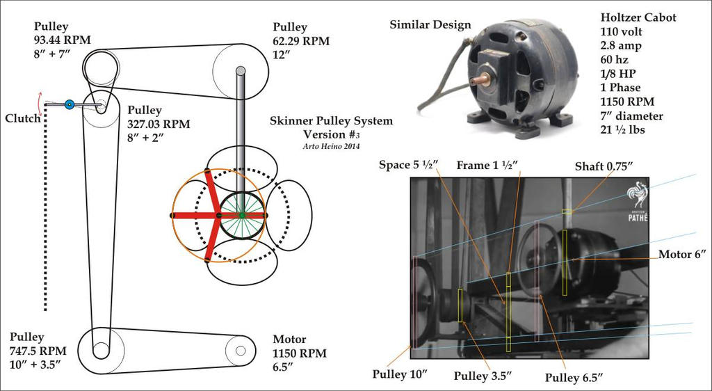
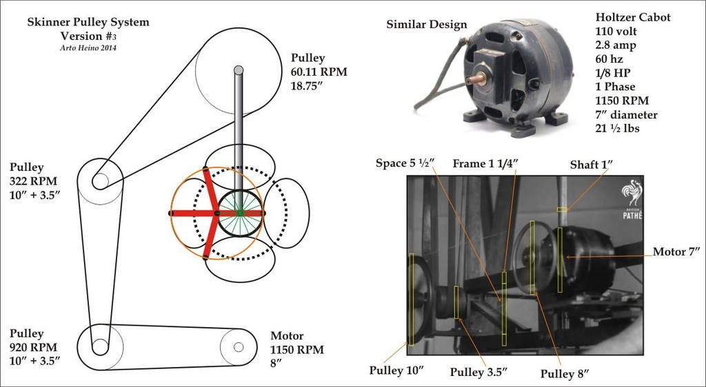
Here is more detail, I have drafted the bottom section and all the dimensions and pulley ratios, all the sizes are now listed and the bottom section (has 2 gears) is build-able. Regarding the top part, the explanations by Aaron was very clear and if you have toyed with these sort of mechanisms you will understand you cannot couple directly to each section, only by allowing the falling weight to drive the rotating lower sections. The top section is almost worked out, no mysteries left just a few more bits to draw and it will be completely replicable. Regards Arto.
It looks like the 4 lever shafts in the upper section are driven at their top end
by being attached to the gears. This would mean that the top end of the shaft is orbiting in a circle. then the shafts go through the 2 way, x/y pivot, then the bottom of them sticks out to drive the translation plate. If the top is going in a circular orbit then the bottom must be as well.
I don't understand why folks are saying it goes back and forth or an ellipse.
If the shaft is directly attached to the x/y pivots rods then it can't spin.
So the attachment at the top to the gear must be something on the order
of a universal joint but that can also pivot on the gear.
Both the top and bottom of those lever shafts seem to describe an orbiting cone shaped motion as drawn in the pics.
To me, both the top (coffee can) and bottom weights are sort of being
driven in a hoola hoop type motion.
It's leverage multiplied 3 times at least. first by the cone motion levers,
then by the coffee can weight, then by the large tall bottom weight.
all 4 large gears in the top and bottom sections (assuming they are gears rather than belts and pullies) are turning the same direction so that must mean that there is another gear between them (the large gears) and the central gear. This could mean there is more mechanical leverage from
the gearing.
The whole machine appears to be bolted together rather than welded.
I wonder if that was by design of maybe back then a welder wasn't too readily available in a home shop.
Does anyone know what those turnbuckles and cables are for on each upright.
there must be a clutch in the upper section. His left hand is on that lever.
this machine might take some time to fully engage the clutch or he might have to turn the weights by hand to help it start.
Thanks for posting this. I'm going to attempt to make a small version
using me meccano set.
"Where I want to go with it as time permits is to have a Scotch Yoke type assembly like in a Bourke Engine but the input is the shaft off centered and the output is the back and forth action moving levers."
Perhaps a hypocycloidal gear would be appropriate in this mechanism.


Leave a comment: