
Aaron
what would you say to this post over on ou,com
ok..the upper shaft may be rotating , but its primary purpose is as a lever. No rotary power is fed in from above. as i see it. Therefore my model achieves the same,. with my linear bearing taking the place of the gimbals..
To be very clear, within the limits of English, the top of the top section rod is describing a circle.
One can see the little driving arm, going around in the rod closest to the camera in the full video.
There is no linear back and forth motion at either end of the top section rod
Now in the one instance, just after the weigh swinging example, one can see the rod passing through the gimbal. Watch the left hand rod in particular. The top of the rod is tracing out a circle and so does the bottom of the rod. The rod does not bend or distort, when the top of this rod is outboard the inner end is inboard the bottom portion of the rod is at all times lined up with the top portion.
It is only three seconds, watch the full video and see the arc/circle that the bottom of this rod traces...
Here it is in a slow motion view...
I hope this helps
Ron
My model seems to work, in that at present it is decouplng the input to output...no current draw extra at total stall....
anyway since it will only take an hour or so i will make another top section this time without a slot or gimbal and try that out
-
upper leads the lower
The upper is ahead of the lower because the upper leads the lower one. Input lever kicks the translation coupler, which then kicks the upper weight, which kicks the lower shaft around.Originally posted by shylo View Post
However, with the momentum of them going, they reinforce each other so there are no bucking forces in the system. Everything is positive reinforcement - it is complete free of "back emf" that I mentioned before - not only is there no back emf that bucks the system, all reaction in the system helps to propel it forward.
But the upper weight definitely dictates what the lower shaft is doing. If you take the lower weight and spin it, it will spin freely around and will not necessary rotate the upper translation coupler at all.Leave a comment:
-
Thank-you
artoj, I was just wondering if there was such a joint.
The big bottom weight doesn't follow the upper, it pushes it.
The power input drives the upper weight only. The lower helps the upper, reducing input. I think?
I'm still trying to get the pendulum.
The bottom of the output center , I think has to be centered with the input when both weights are passing over TDC of " always falling" That is a very short time of equalibrium?
Also the upper weight is hard connected to the drive , where the lower shaft is free to spin, but when you run it , the upper always settles 90 deg. ahead of the lower.
It does spin alot of mass with very little input.
artvLeave a comment:
-
More Details
Hi all , I have lots of work to get all the sizes close to 95% correct, as this is more of a replication drawing, rather than a actual build, I will continue until I have all the parts working together. Here are 2 more drawings that should help those who are needing a few more ideas.
The isometric drawing needs an update, this is where I am at the present, The four 1/4" rods that wrap the lower wobble shafts, pull the top and the bottom bearing housing collars together, both upper and lower shafts are hollow.

This is the type of Universal joint that I was originally thinking it could be, after checking with about 300 possible sources in 1939, this would be the most likely design, and it fits great. Regards Arto.

Leave a comment:
-
latest videos
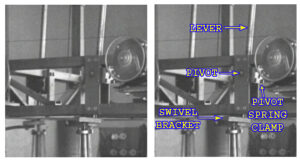
now over on ou.com they seem to think that the lever is a shaft.. to my understanding it is a lever ,
that levers , and it is not spinning.
anyway enjoy the videosLast edited by eltimple; 06-10-2014, 05:23 PM.Leave a comment:
-
Nice heavy work there.. i do the same on my model see youtube link above..But this part is all standard physics...and with a lot of mass you get a lot of inertiaLeave a comment:
-
Quick and dirty build out of 1/2 pipe to feel forces:

Total weights=25lbs.
There's no universal joint, so I just put the bottom pipe cap in a hole I had in my driveway, which has since been enlarged. You can see that at the bottom of the picture toward he left. There's so much torque bearings aren't needed for this type of demo.
When I stand this up and hold on to the top end that has the red cap on it, it is easy to feel the rotational force by moving it around in an upside cone shape, which is how I describe the path the main pipe length creates in the air after one full cycle. When holding on to the pipe at the top with my hand as hard as I can, it is impossible to stop the rotation.
There's no counterbalance here, but it's easy to lean back with an outstretched arm and walk around in a circle to counterbalance it. When doing this, it feels like you are just leaning the top of the pipe slightly to the right to make the bottom weight fall (if proceeding clockwise viewed from the top).
Thought this might be a useful way for others to play with the forces involved without spending a lot of time or money on builds.
Not sure if this is related, but the cone shape of the path travel and the forces remind me of the original Faraday motor, though in that case the wire is attracted upwards to be aligned with the magnet horizontally but is continually rotated around in the process as it tries to become aligned (but it never does!). See right portion of image below. It's like the wire is continually falling toward the magnet but is always being moved out of the way by centrifugal forces. Fascinating how the continual application of steady, unswitched, electrical forces results in continual rotation without the wire or magnet ever becoming closer to each other. Gravity is also a continual force so it's interesting to see a similar solution applied.

Leave a comment:
-
 not sure about the swash plate as i call it....the axis or central axle will bolt to a plate on linear bearings, allowing for up to 10mm back and forth motion

not convinced this is very good although it seems to replicate the plate, the smaller weight which is attached to the palte istelf does not wobble as far as i can see, it only shuffles back and forth to change the center of gravity of the large weight..
having trouble seeing were the gain is...since while a child could hold the effiel tower unside down , and could manipulate the weght over a small arc, the energy used to displace must be equal to the energy used to return something to its original position.. I will get this working in some fashion tho
update
ok i think i see this clearly now...gravity is only part of the solution...
In my previous post i mentioned how while a child could move the effiel tower if it were balanced on its peak, any input energy to move it off center is equal to the energy to return it to equilibrium..
Now while the device is chasing a continually moving center of gravity , how do we move the center of gravity without expelling the same amount of energy that is gained?
I believe that the secret lies in the centrifugal forces of the second weight. As it spins round and around, its centrifugal force is used to push the main shaft or axis back and forth in its slot..it is that "Extra Energy" that moves the axis, which allows a change in the position of the center of gravity..when you study the orbit of the smaller weight it is clear that it is creating a force vector in the direction of the slot, that vector reverses every 180 degrees..
the energy required by simply moving the center of gravity would cancel as per standard laws..but very little of the input energy is knocking the shaft off center , it is mostly centrifugal force doing the knocking..
I wonder if there are any springs on the sliding mechanism. since the centrifugal force could both compress springs and shift centers of gravity
see my progress on the build here
1939 Skinner Gravity Engine replication - YouTubeLast edited by eltimple; 06-09-2014, 09:18 PM.Leave a comment:
-
starting from the bottom and working up...m6 lathed down to 4mm for the universal joint running in 6mm bearings...4mm steel shaft may be replaced with 6mm brass threaded rod depends how well the weight stays put on the shaft arm
 Last edited by eltimple; 06-08-2014, 12:32 AM.
Leave a comment:
-
Update V#4
Here is the latest design form, the rest is just details and small adjustments, the top wobble design is sound and reliable, these are the sort of designs that a factory production machine designer like Skinner would have done. I have supplied parts to hundreds of old machines over the years many customers that used these types of set ups for bottling and such, by adapting old 1930's, 40's etc equipment they saved money. So if someone wants a accurate replication, these outlines should help. More pages for all the top, bottom and middle wobbler are in the works, looks like about 40 pages of details and engineering to finish. Regards Arto.

Leave a comment:
-
output shafts
Are the shafts not all connected to the single output drive? It looks like there is a sprocket at the bottom, I would assume they all connect to a central shaft.
Also the four weighted arms are offset evenly. Every other one is 180 degrees out of sync, when #1 is at the farthest point on the outside of the frame, #2 is at the farthest inside the frame, #3 outside, #4 inside.
The top connecting rod looks like it just has a rod attached to the side of it at the bottom which goes through the transition plate?
artvLeave a comment:
-
a small input at the top tilts the plate so that the small wieght searches for the center of gravity or equilibrium, and that is further enhanced by the larger weight......which adds to the amplification...
so if i take some of that energy at the output gear and run a shaft back to the top it will self sustain right?, ..well i can try lol
I think 4 are used in an effort to cancel the stray forces out, but that would imply that all four output shafts are linked via chain to keep in sync which gets complicated up at the swash plateLast edited by eltimple; 06-07-2014, 11:48 AM.Leave a comment:
-
spring
Hi All, This is very interesting ,I've watched the video over and over, at 29 sec mark when he grabs the lower weight and pushes the upper it seems to be spring loaded. Has this been discussed or is it just the action of gravity?
Also it looks to me like where the lower weighted rod goes in the transition plate that it floats freely in there?
Also the upper connecting rod is rotating as well as going back and forth ,looks like it is turning maybe a small wheel with a pin sticking out the other side and that is what is turning the transition plate? But this is just a guess.
Whats the reason for 4 why not just one ,or maybe eight probably to offset the wobble action ,to balance seems it should balance with any number?
Time to start gathering some parts.
 artv
artv
Leave a comment:
-
Thank you Aaron for bringing this forward and creating interest in it.
And thanks to the members who have started studying it.
I have examined the video to a certain degree and find this a very interesting device. As I see it, it creates a continuous falling action for the larger lower weight by changing the center of gravity.
Just a few observations.
I believe that the top rod is in an actual circular motion connected to a rotating arm at the very top where the power is being transmitted into the machine.
Just because the lower hinge point for this rod is moving backward and forward doesn't mean that the rod isn't going in a full circular fashion.
The motion can be seen best at the very top of the machine, at the start of the video.
I also believe the top rod is connected directly and securely to middle connecting plate, as a bolt can be seen on the side of the plate that would likely be used to fasten it.
Anyway just my take on some of the parts, hope it helps.Leave a comment:
-
would you say that the large weight, although appearing vertical , is probably leaning 10 to 15% into the direction of rotation?
also , i am trying to understand why the weight is fixed at its base and not at either end, unless of course fixing the weight at its end forms a mechanical moment or lever of sorts.. off to buy nuts and bolts and a lot of heavy washers since getting the weights right may be a challenge..
looking at the weights again
estimated at
5 and 3/4 x 7 therefore volume is 181 square inches
4 x 33 therefore volume is 414.69 square inches
suggesting that the larger weight may be around 2.5 times the smaller although the weight distribution is probably the black art here and not the values themselvesLeave a comment:

Leave a comment: