This forum is preserved as a permanent archive. The community continues at eMedia Press.

Announcement

Collapse
No announcement yet.

Newman Motor Finally Explained?

Collapse
X
 
  • Filter
  • Time
  • Show
Clear All
new posts

  • Vinyasi
    replied
    Oops. Corrected Simulation and Enhanced RPM with neon bulb.

    Originally posted by Vinyasi View Post
    The batteries power the circuit. They do not provide the over-voltage for the coil. That's provided by the spinning magnet.

    But the coil has to be charged up with voltage in order to acquire the magnet's energy. And the coil has to be massive so as to be able to hold a very large charge of voltage.

    The coil does not provide any power. It simply acquires it from the magnet.

    The capacitor, if there is one placed in parallel with the coil, helps suppress spikes. Spikes drain the battery pack without providing any gain in the coil. So, if the capacitor is sufficiently large enough, then the spikes disappear.

    With this approach, negative current manifests in the batteries, and both the current and the voltage in the coil is greater than what the batteries can supply it, because the spinning magnet is providing a very large AC influence that the coil responds to by acquiring it and transferring it to the batteries. The current, thus produced, neutralizes the current coming out of the batteries so that they can become recharged. And the coil retains a huge charge of voltage to engage the spinning magnet with enough feedback that the magnet is able to accelerate its rotation and thus give even more energy to the coil until the coil can't assimilate any more and finds its plateau of spin rate.

    From this assessment, it's possible to disprove any claims of overunity.

    On the other hand, it's impossible to ignore the massive importance of a spinning magnet.

    As Paul Babcock has said on numerous occasions: "Magnets have energy."

    Pray for Newman - Discussion on the talk page of Wikipedia for the article entitled: Decoupling capacitor.

    Chapter Six of Newman's Book plus additional material.

    ASC file for simulating Newman's Motor in LTSpice.

    My discussion of this simulation on YouTube.
    This was a flawed simulation which is evident in the zero input of V(in).

    The following attachment and videos are corrected and enhanced with a higher RPM and the addition of a neon bulb making possible the reduction of the simulated magnet's input voltage to a wee 255 micro volts using a mere 700 pico henries to transfer its spin energy to the coil. The total input from the spinning magnet is a mere 8 watts to succeed at negating the amperage on the battery pack.

    Despite this latest simulation requires a tightly coupled spinning magnetic field and the coil, it may be possible to build this using the design exhibited in the attachment below along with the latest videos.

    LTSpice file ...


    Hosted at ...


    Search for my videos on this simulation
    Attached Files
    Last edited by Vinyasi; 01-12-2018, 06:07 PM. Reason: updated schematic image

    Leave a comment:


  • vidbid
    replied
    Originally posted by Vinyasi View Post
    Lowering the capacitor's value helps to more fully suppress the spikes of amps drained from the battery pack. But it also makes it increasingly difficult for the simulator to process an increase of data points to trace.

    Lowering the inductance on L2 (representing the permanent magnet) helps increase voltage on the coil, L1, but at the expense of draining more amps from V3. I guess this implies a smaller magnet of super duper strength?

    I go with Dr. Hastings' analysis of Newman's 145 lb. coil with 14 lb. magnet described in chapter six of Newman's book. I've managed to simulate some of that data...

    16k H and 50K Ohms on the coil. 45 & 1/3 duty cycles per second. I rounded upwards to 50. 304 volts in. I rounded downwards to 300. 667 volts on the coil. I achieved 660. 1.2mA in. I achieved a baseline of 45-50 amps drained from the battery pack, at V1, spiking at 600mA twice per duty cycle at the start and end of each self-short on the coil. Newman's device had an average of 50 mA spikes on the coil. Mine has 21 mA non-spiking curved waves.

    The following are the two ASC files, saved from LTSpice XVII...

    The Energy Machine of Joseph Newman

    The Energy Machine of Joseph Newman, v2
    @Vinyasi :

    Very good post. Thanks for the videos. Very good content.

    Newman = one of a kind

    I also like your video on the Tesla Special Generator, Viz. a vintage watt-hour meter's use as a dipole.

    I appreciate your conversational style of videos, and the insights offered are very eye-opening.

    Allow me to return the favor: https://www.youtube.com/user/freeanergy

    Leave a comment:


  • Vinyasi
    replied
    Newman Motor is Powered by its Rotating Magnet, not by Batteries!

    The batteries power the circuit. They do not provide the over-voltage for the coil. That's provided by the spinning magnet.

    But the coil has to be charged up with voltage in order to acquire the magnet's energy. And the coil has to be massive so as to be able to hold a very large charge of voltage.

    The coil does not provide any power. It simply acquires it from the magnet.

    The capacitor, if there is one placed in parallel with the coil, helps suppress spikes. Spikes drain the battery pack without providing any gain in the coil. So, if the capacitor is sufficiently large enough, then the spikes disappear.

    With this approach, negative current manifests in the batteries, and both the current and the voltage in the coil is greater than what the batteries can supply it, because the spinning magnet is providing a very large AC influence that the coil responds to by acquiring it and transferring it to the batteries. The current, thus produced, neutralizes the current coming out of the batteries so that they can become recharged. And the coil retains a huge charge of voltage to engage the spinning magnet with enough feedback that the magnet is able to accelerate its rotation and thus give even more energy to the coil until the coil can't assimilate any more and finds its plateau of spin rate.

    From this assessment, it's possible to disprove any claims of overunity.

    On the other hand, it's impossible to ignore the massive importance of a spinning magnet.

    As Paul Babcock has said on numerous occasions: "Magnets have energy."

    Pray for Newman - Discussion on the talk page of Wikipedia for the article entitled: Decoupling capacitor.

    Chapter Six of Newman's Book plus additional material.

    ASC file for simulating Newman's Motor in LTSpice.

    My discussion of this simulation on YouTube.
    Attached Files
    Last edited by Vinyasi; 01-06-2018, 03:34 AM.

    Leave a comment:


  • Vinyasi
    replied
    Simulation of Joseph Newman in LTSpice

    Lowering the capacitor's value helps to more fully suppress the spikes of amps drained from the battery pack. But it also makes it increasingly difficult for the simulator to process an increase of data points to trace.

    Lowering the inductance on L2 (representing the permanent magnet) helps increase voltage on the coil, L1, but at the expense of draining more amps from V3. I guess this implies a smaller magnet of super duper strength?

    I go with Dr. Hastings' analysis of Newman's 145 lb. coil with 14 lb. magnet described in chapter six of Newman's book. I've managed to simulate some of that data...

    16k H and 50K Ohms on the coil. 45 & 1/3 duty cycles per second. I rounded upwards to 50. 304 volts in. I rounded downwards to 300. 667 volts on the coil. I achieved 660. 1.2mA in. I achieved a baseline of 45-50 amps drained from the battery pack, at V1, spiking at 600mA twice per duty cycle at the start and end of each self-short on the coil. Newman's device had an average of 50 mA spikes on the coil. Mine has 21 mA non-spiking curved waves.

    The following are the two ASC files, saved from LTSpice XVII...

    The Energy Machine of Joseph Newman

    The Energy Machine of Joseph Newman, v2
    Attached Files

    Leave a comment:


  • Vinyasi
    replied
    added links to his book


    Fourth edition, full text...
    The Energy Machine Of Joseph Newman, 4th Edition : Joseph Newman : Free Download & Streaming : Internet Archive

    Eighth edition, full text...
    This is a high quality scan of the out-of-print seminal work of inventor Joseph Newman. Unfortunately he passed away last year, so I feel it is important to...


    Originally posted by BroMikey View Post


    Leave a comment:


  • Vinyasi
    replied
    link corrections

    Originally posted by nilrehob View Post
    A few days ago I found out about this Ukrainian invention:
    404 Not Found
    Above link is dead, but archived here ...


    Originally posted by nilrehob View Post
    What if the rotating magnet where placed inside the coil?
    This might explain how Newmans motor works and why he is shorting the coil after each impulse?

    Also interesting in this context is one of Tesla patents nr 390721:
    Retrieving Patent from PAT2PDF.org - Free PDF copies of patents: Download and print!
    (BTW, its "best available copy")
    Correction to link by adding a leading zero ...


    Originally posted by nilrehob View Post

    Leave a comment:


  • pjotterkjen
    replied
    More Info and an interesting observation

    All,

    I was just reading a document that Patrick Kelly has on his website:
    http://www.free-energy-info.tuks.nl/DonKelly.pdf

    In this document on page 49, the following is written:
    "The project work in this area, to date, has already found that off-the-shelf -tinned-copper buss conductor wire produces approximately
    three times the magnetic field level compared to plain copper conductor wire." [emphasis added]

    The above would mean that, if true, instead of having to create a coil with N windings, we could achieve the same results using the mentioned type of wire but N/3 windings.
    Or, when having such a coil with N windings, we'd be able to increase the magnetic field by a factor three. (!)

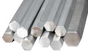
    The same occurs to me with the magnets used by Newman. The first models used circular ceramic magnets, but the he changed to the long models with the hexagonal placed magnets along the ax which were neodymium type magnets.

    Then, thinking ahead of my redesign, the commutator was used to obtain two requirements:
    1. each half revolution the input voltage over the coil should flip polarity to keep the push or pull on the magnet such that it would keep rotating;
    2. create an amount of DC pulsed inputs to the coil by the FIRE segment.
    The SHORT segment was eliminated by the use of the capacitors over the coil which suppressed the Back EMF.
    So, it is obvious this commutator could be improved on too.
    Sharp high voltage and supershort DC pulses should improve the alignment of copper atoms in the main coil.

    Also, the energy that goes from the coil into the capacitor when the magnetic field collapses could be used to be fed back to the input source using Bedini SG circuitry. Or, when using two battery sources, one would be the input battery and the other would be recharged, and after a while these two batteries could be swapped so that the system becomes a self-running device.

    Interesting facts and thoughts I think, while progressing.

    pjotterkjen
    Last edited by pjotterkjen; 10-12-2017, 02:34 PM. Reason: name correction

    Leave a comment:


  • pjotterkjen
    replied
    Other info on Newman

    All,

    for those that have interest in reading more about Joseph Newman, here are two additional links:

    1. RexResearch page Newman
    Joseph W. Newman: South African Patent Application #831296, "Energy Generation System Having Higher Energy Output Than Input"

    2. Patrick J. Kelly eBook edition 2017 Chapter 11, Joseph Newman's Motor.


    pjotterkjen

    Leave a comment:


  • wantomake
    replied
    Looks good

    Originally posted by vidbid View Post


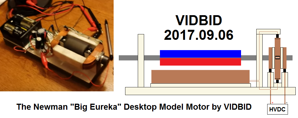
    Correct. My design is base on Newman's Big Eureka, only mine will be a desktop model. Initially, the HV-MOT will be lower and then an additional HV-MOT for upper level later.

    I thought about using an old monitor fly-back yoke HV transformer to produce the HVDC, but I'm not certain if there will be enough current to do that. We'll see.
    Vidbid,
    Good picture with diagram. Hope all goes well as you build.

    I will be making adjustments to get better results. The first machine I replicated long ago ran with just a single reed switch. One 9 volt battery. The coil was single wire winding of 38 awg from a MOT primary coil.

    It was a very crude build but very interesting as well,
    Back to coffee and thinking.
    wantomake

    Leave a comment:


  • vidbid
    replied
    Desktop Newman Motor

    Originally posted by wantomake View Post
    Vidbid,
    Thanks for reply.

    So you're planning the long motor build. That's were I got the idea to use two coil setup on top and bottom. Also from the videos posted here. That guy was using one MOT coil on the bottom of his unit. I see you must follow the established setups for this machine. The round "upright" machine must be built certain way different from the long or horizontal machine.

    Anyway just thinking while typing,
    wantomake


    Correct. My design is base on Newman's Big Eureka, only mine will be a desktop model. Initially, the HV-MOT will be lower and then an additional HV-MOT for upper level later.

    I thought about using an old monitor fly-back yoke HV transformer to produce the HVDC, but I'm not certain if there will be enough current to do that. We'll see.
    Last edited by vidbid; 02-15-2019, 05:58 AM.

    Leave a comment:


  • wantomake
    replied
    Long motor

    Vidbid,
    Thanks for reply.

    So you're planning the long motor build. That's were I got the idea to use two coil setup on top and bottom. Also from the videos posted here. That guy was using one MOT coil on the bottom of his unit. I see you must follow the established setups for this machine. The round "upright" machine must be built certain way different from the long or horizontal machine.

    Anyway just thinking while typing,
    wantomake

    Leave a comment:


  • vidbid
    replied
    Originally posted by pjotterkjen View Post
    vidbid,
    You may want to review the presentation of Geoffrey.

    Geoffrey states clearly that only 12-3 and 6-9 o'clock are interconnected with the small commutator rings, And that's all, he said. So, you may be right about the Big Eureka not having an internal commutator, but if Geoffrey is right (and I'll assume he is) then you need to adjust your drawing.
    The two pairs of copper segments were connected through the bridges you draw, but not all four. Something like this: A1-A2 and B1-B2.

    The voltage applied by the batteries when the rotor is in one of the FIRE segments will generate a big electromagnetic field which interacts with the magnetic field of the magnets on the rotor and create a torque, hence it starts turning.

    So, we would have four FIRE segments and four BLANK segments.
    The absence of SHORT segments is because Newman used capacitors that were helpful in suppressing the sparks. No need for complicated commutator design anymore. The capacitors are charged when the coil discharges its stored energy during the BLANK segments. Actually, the coil with the capacitors and the inductive reactance (or resistance when the rotor is not turning) represent a simple RLC circuit.

    pjotterkjen
    I shall give your statements consideration.

    Leave a comment:


  • pjotterkjen
    replied
    Originally posted by vidbid View Post
    The book is a good starting place, no doubt.

    I think a good finishing place is building a Newman motor based on Big Eureka, specifically, the Big Eureka commutator.

    There's only two rotating contacts, though, they are segmented. I think that there are about four segments per contact, but then there is the copper shorting band (so-termed by me,) and I see not mention of that in his book, and that would be because it came later, I believe.

    So, there's my two cents on it.

    vidbid,
    You may want to review the presentation of Geoffrey.

    Geoffrey states clearly that only 12-3 and 6-9 o'clock are interconnected with the small commutator rings, And that's all, he said. So, you may be right about the Big Eureka not having an internal commutator, but if Geoffrey is right (and I'll assume he is) then you need to adjust your drawing.
    The two pairs of copper segments were connected through the bridges you draw, but not all four. Something like this: A1-A2 and B1-B2.

    The voltage applied by the batteries when the rotor is in one of the FIRE segments will generate a big electromagnetic field which interacts with the magnetic field of the magnets on the rotor and create a torque, hence it starts turning.

    So, we would have four FIRE segments and four BLANK segments.
    The absence of SHORT segments is because Newman used capacitors that were helpful in suppressing the sparks. No need for complicated commutator design anymore. The capacitors are charged when the coil discharges its stored energy during the BLANK segments. Actually, the coil with the capacitors and the inductive reactance (or resistance when the rotor is not turning) represent a simple RLC circuit.

    pjotterkjen
    Last edited by pjotterkjen; 09-06-2017, 04:13 AM. Reason: correction

    Leave a comment:


  • vidbid
    replied
    Progress Report

    Originally posted by wantomake View Post
    Vidbid,
    How is your build going? I know your commutator is including the "shorting" segment. Any results would be good to read.

    Mine aren't encouraging so far. I wound my coil as two separate coils. Top and bottom of the pvc 4" union piece. I wanted to use one coil as motor and the other as generator. But no motoring yet. Using 17 9 volt batteries in series to power the machine. The timing is set. Good contacts on commutator. Only thing can figure is the coil needs to be re-wound.

    wantomake
    Hi wantomake,

    Not too much to report.

    I think that I'm going to use a flat copper disk as the commutator.

    For example: 3" Dia x 1" Thick Copper Round Disk Disc Rod Bar Stock 99.9% Cu

    3" Dia x 1" Thick Copper Round Disk Disc Rod Bar Stock 99.9% Cu | eBay

    I could center-tap it. Then, slot out the places for the contacts with epoxy holding the contacts and also providing the non-conductive material for the spaces.

    I'm still working on my design.

    Coils will be provided by microwave oven transformer high voltage coils.

    Not sure as to what to make the armature shaft out of. I was thinking fiberglass for its nonmagnetic properties; however, Newman said to use steel hex bar.


    For the slip rings, I'm still considering my options. Maybe I can find some off an old motor.


    For the magnets, maybe center-hole type Neodymium magnets could be attached to a hex bar shaft.


    Anyhow, that's where I'm at.

    Leave a comment:


  • wantomake
    replied
    Vidbid,
    How is your build going? I know your commutator is including the "shorting" segment. Any results would be good to read.

    Mine aren't encouraging so far. I wound my coil as two separate coils. Top and bottom of the pvc 4" union piece. I wanted to use one coil as motor and the other as generator. But no motoring yet. Using 17 9 volt batteries in series to power the machine. The timing is set. Good contacts on commutator. Only thing can figure is the coil needs to be re-wound.

    wantomake

    Leave a comment:

Working...
X