
Originally posted by Ufopolitics
View Post
-
Originally posted by Ufopolitics View Post
Mark,
I will just RE-QUOTE BELOW the ONLY PART I keep getting from you...No matter how many times I Insist You do NOT Add Switch Angle from Brush/Segment to Magnetic Interaction Sweep...JUST BECAUSE, THEY COEXIST, ROTATE, MOVE, TURN WITHIN THE SAME EXACT TIME/SPACE...Then You tell me I am "misrepresenting what you're saying!!!
Regardless, you keep adding this "brush angle" to Magnetic Interaction Angle,which happens to take place right WITHIN THOSE 36 DEGREES!!
...are you for real man?...
Let me guess...did you even see my previous post? did you read that?...am sure you did NOT...or maybe you did not understand it?
And, here I am ending my discussion with you Mark related if you do add or you don't...finished....We were supposed to end this argument way before getting again on the same boat.
I realize I am completely wasting my time every second I spent writing to you...
You have been so far the more stubborn person, that I have EVER dealt with...and the glass is full.
It is time for others to build and show...over
Now "transfer" all of your posted arguments with me here...and take them to your close friend Midaz the Hijacker of this Thread...like you have been doing lately...adding more fuel to the fire..
ASK ME IF I GIVE A "WHO"?
And last...If You have any Machines, which are based on a SINGLE COMMUTATOR...AM ASKING NOT TO EXPOSE RESULTS HERE...Last edited by Ufopolitics; 05-22-2015, 10:36 PM.Leave a comment:
-
Originally posted by HuntingRoss View Post
No need to guess. It was mentioned at the time...
Originally posted by Ufopolitics View PostI accept that it is not written in tablets of stone, that it is approximate. You should have noted that I have always stated that my method for calculating the 'OFF' time is an ESTIMATE...an approximation to enable the 'would be' designer a guide to setting the initial timing before winding the motor.Originally posted by Ufopolitics View Post
Despite the fact that the 'OFF' angle is an approximation, I didn't think we would want to actively fine tune the motor in that zone.
Notwithstanding, if this confused anyone...Apologies. It was unintentional.
On a better point. It can be seen (or it should have been noted) that my method of calculating the timing for the 10 pole motor agrees with UFO's method of calculating and achieves the same result. It seems futile to avoid agreement when the methods of calculation all point to agreement.
If we want to illustrate 'confusion', consider the following quote -
Originally posted by Ufopolitics View PostOriginally posted by Ufopolitics View PostLeave a comment:
-
Simple Geometry Applied to Asymmetric Motors
Hello to All,
This Post is related to previous debates about sweeping angles between Switching Area versus Magnetic Interaction Angles...since it seems there are still confusion about it...
A while back Veproject1 open a Thread called "The Two Circles Paradox"
The main video was "Aristotle's wheel paradox"
The solution was simple...however, many could not see where was the confusing concept.
The same exact thing applies to the way we "see" a Commutator Switch level circle and Brush, versus a Magnetic Interaction level circle which is always bigger.
Previously, on the Five Film Strips I have uploaded (shown below), We agreed that Commutator Segment sweeps TWICE its Circumference Size related to the Brush size, meaning the Coil being energized (ON) for twice the commutator arc segment circumference...
[IMG]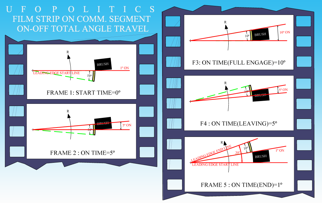 [/IMG]
However, this fact, when we compare same Angle to a larger Radius Rotor ...things "change".
So, I put together this Diagrams with "Circles Paradoxes" related to Commutator/Brush Angles, versus Rotor Coils/Stators Angles:
[IMG]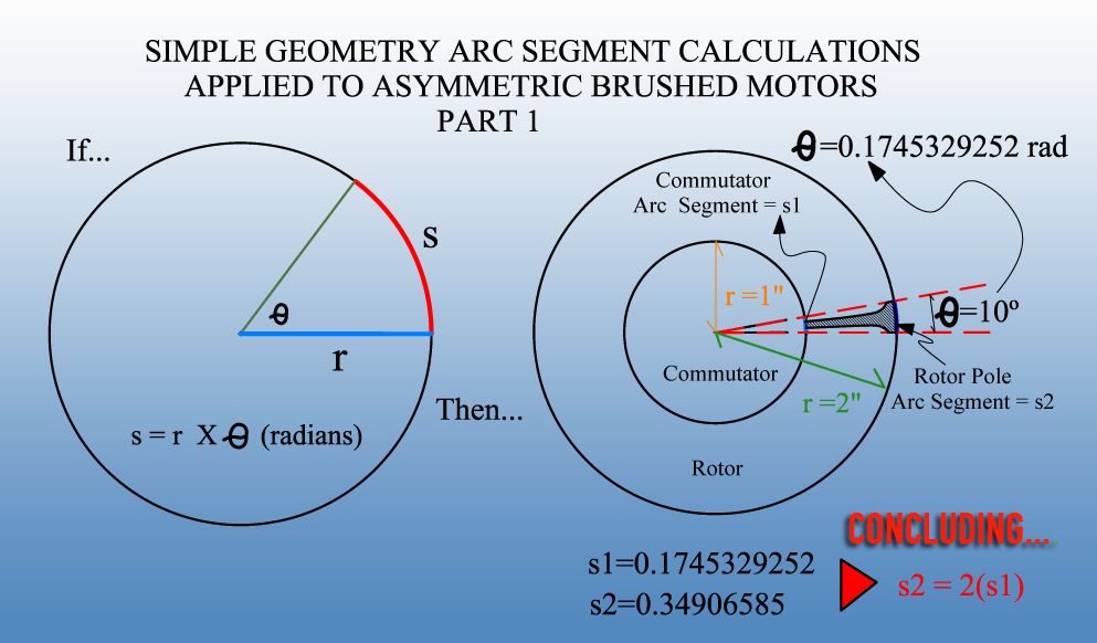 [/IMG]
On Part 1 above, Left Image, is shown the simple way we calculate an Arc Segment (s) based on Radius (r) and given Angle Theta.
On Right Image, we see the same application for a Motor where Commutator/Rotor Ratio is 1:2, so Commutator is r=1" and Rotor is r=2"
Then a Rotor Pole Arc (s2) would be TWICE the Commutator Arc (s1)
Then we have Part 2 Diagram:
[IMG]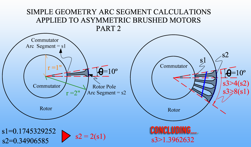 [/IMG]
On Right Image above we see a Four Pole Coil...of Arc Segment s3, which is greater than, Eight Times the size of the Arc Circumference from Commutator Segment.
I displayed "greater than" and not "equal to" sign, because we must add here the slot gap distance between each pole.
Which means that...No matter if a Brush of the same face/size as comm. segment, takes TWICE that sweep angle at ON Time at Commutator Circle Level...That Time ON only means One Eight (1/8) of the Total Magnetic Interaction Sweeping Angle taking place at that Four Pole Coil.
I have written here previously that ALWAYS a Commutator Radius will be Smaller than Rotor Radius...it is an established operating equation that applies to Symmetry and Asymmetry whenever designing motors.
Therefore, the Angles established at Switch/Commutator/Brush Segments would always take MUCH LESS TIME than the Time of each Magnetic Interaction angle takes to fully develop from that Switch ON-OFF sweep angle/time.
If we go by Bisectors on this example...then, Bisector from that Coil would be set greater than (>) Four (4) Times the Commutator/Brush segment sweeping area.
Setting the ON-OFF Time to be s2= 0.35 travel distance (which is TWICE the size of comm. segment based on Diagram= 0.175)...And Bisector being 4 times s1, or (0.175 X 4)= 0.7 which is exactly TWICE the ON-OFF distance traveled.
Regards
UfopoliticsLast edited by Ufopolitics; 05-22-2015, 02:44 PM.Leave a comment:
-
Mark,Originally posted by HuntingRoss View Post
What is NOT "basic Science principles" is that even being warned by many here, mainly from me about the wrong settings on your timing angles, by keeping ON the leaving coil passing south bisector...you STILL proceeded to test this known to be failed tests...and then post results which made look "your beast" as a very weak machine.
The Single Commutator would never, ever could be compared to dual commutator machines.But what I have said about the single comm build is this. It is a very simple way for novice builders to get into a new subject and learn without the added technical issues of chopping and joining the motors which experienced builders would be more comfortable tackling.
Single Commutator represents Symmetry, Dual Commutator represents Asymmetry...Night and Day difference!
In the very beginning of this Thread a member built the single comm three poles...at that time there were all the differences established between both types.
, not meaning it could NOT be less or it could NOT be more. However, any TOTAL Angles left between last coil bisector to South Stator Bisector MUST BE mentioned at all times!I also conclude that we still do not agree on the basis for estimating the 'OFF' times for motor design being you have not responded to my last post on the topic.
Happy Hunting
mark
UfopoliticsLeave a comment:
-
But that's the funny thing UFO. You see my exploits as 'constant personal failure' whilst I see my knowledge and experience growing in a new discipline. As the well known phrase goes, that's a hundred ways not to make a light bulb. The world would be a darker place if people were so easily discouraged by such negative comments.Originally posted by Ufopolitics View Post
You appear to be sensitive to my comment about the single comm. I make no claims that it is better or worse than double comm, simply the conclusion that was drawn was not derived from the question that preceded it. That is basic science principles.
But what I have said about the single comm build is this. It is a very simple way for novice builders to get into a new subject and learn without the added technical issues of chopping and joining the motors which experienced builders would be more comfortable tackling.
I also conclude that we still do not agree on the basis for estimating the 'OFF' times for motor design being you have not responded to my last post on the topic.
Happy Hunting
markLeave a comment:
-
Garry, you definitively have a good point there.Originally posted by GChilders View Post
And if we add the mechanical bouncing of a spring mounted brush...at every air gap...then we start complicating the "scenario" even more...
What I have done before and had excellent results is to install a 1K resistor from segment to segment...this, besides reducing sparking/arcing a lot...if we add them just at bottom commutator the output voltage increases quite some...
So far the "Clean CAD's" Diagrams could never predict the actual issues found in every real development...
We are working from neat and clean theories when it comes to designs...then find the unpredicted results from reality.
Regards
UfopoliticsLeave a comment:
-
Does electricity start to flow when brush initially touches com element?
@UFOPolitics
My question is does the electricity that is being fed to the motor coils begin to flow the millisecond that the brush touches the commutator element? This violates most electricity laws. Electricity always takes the path of least resistance. I do not think that there will be a very long period where two neighboring commutator elements will be energized simultaneously with the exact same amount of resistance between the coils brushes and wires leading into them. Just food for thought.
Cheers
GarryLeave a comment:
-
Is this Confusion?...or else?
Originally posted by grounded View Post
Negative Mark,Originally posted by HuntingRoss View Post
Dual Commutator Machines has been proven to be FAR superior to ANY single commutator designs, no matter how far you get into "trying" to make them better.
Just because of your constant personal failures on dual commutator machines...does not need to be "extended" into "General Comments" like above Mark.
Single Commutator KILLS by reversing polarity in every turn the collapsing field Radiant that tries to enter the system...this has been long time ago discussed/debated in my First Thread here.
Dual Commutator Machines generates a "One Way Flow" within rotating fields...this has long, very long implications that range from flux flows to electrical fields flow...besides no constant colliding of electrons/flux like a Single, old commutator does.
This effects can NEVER be reproduced with a Single Comm deal.
UfopoliticsLeave a comment:
-
-
Mark
Can you explain this? "And given the 5 frame agreement that a comm sweeps over a brush with an angle equal to twice its face width".
Its early for me but I'm just not following.Leave a comment:


Leave a comment: