
Howdy UFO, all,
RE: open to comments. Could the following explain your and HR's diff. views
due to a conflict of terminology?
Assuming a 1" wide comm. element and 1" thick brush. Also assume the dia
or circumfrence as such to require 10 deg rotation to cause 1" 'travel' on comm.
surface. It will take 10 deg rotation to bring brush's first contact to center the brush
upon the comm. element. It takes 10 deg more to turn the switch off. Thus the 'coil' or
pole is energized for 20 deg. of rotation.
Please forgive if I'm all confused also.
Also, UFO, I've sent you an email re: another matter.
Regards to all....jw
-
Misrepresentation
Hi UFO
I agreed to let other members respond and comment on this post, but I didn't agree to be misrepresented.
Being true to my word, I shall wait a day or two (longer if you advise) before commenting.
Happy Hunting
markLeave a comment:
-
About Angles of Interaction Facts...
Hello to All,
Mark (Hunting Ross) and I have been discussing lately on a very important issue, which directly relates to setting the correct timing on Asymmetrical Machines. The main side is that Mark kept adding the two angles involved at each interaction , which are brush/commutator segment Plus(+) Magnetic Interaction Angle taking place at energized coils and Stators Fixed Angles, all within the same rotation shaft, and taking place at the same exact time.
It is very well known that Symmetric Motors, which is where we base our Asymmetric Designs structures, always keep the Commutator Diameter smaller than Rotor Diameter.This is done in order that commutation sweep Time will always be contained within each interaction angle Time.
In very few motors I have seen a Commutator where its diameter is almost the same as the rotor diameter. However, they do exist and mostly are used as heavy torque motors.
In high speed motors the commutator is much more smaller than rotor diameter.
But, what I have never seen...is a Commutator which is much bigger than rotor size.
When we start analyzing the length of each coil circumference related to commutator segment circumference...then we see a major difference, where coils are always bigger than segments.
Above is something that must of Us know, however, I consider it very important at time to analyze deeper this topic.
Now, getting into the discrepancy issue between Mark and I:
[IMG]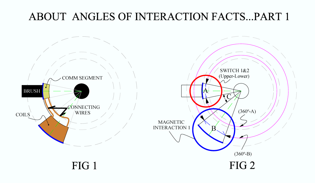 [/IMG]
Above we have FIG 1 which is a simple Rotor with just one Commutator Segment attached by connecting wires to the Coil.
On FIG 2 We see the same structure, but reflecting the angles participating in this single Interaction. I have encircled the Brush and the Comm Segment defined by Angle A, within a Red Circle, which is the Switch, (in our case with Asymmetrical Motors, is understood we have SW 1 & SW 2, one on top of the other when looking on a top view like shown).
Then we have the Magnetic Interaction 1, from Coil and section of Core, that is within Angle B into a Blue CircleSwitching Interaction Angle sweep within the Stators Angles of strength from center to center, just because carbon brush and copper segment-contact plate from commutator are not dependent from absolutely any magnetism restriction, nor magnetic interaction at all.
[IMG]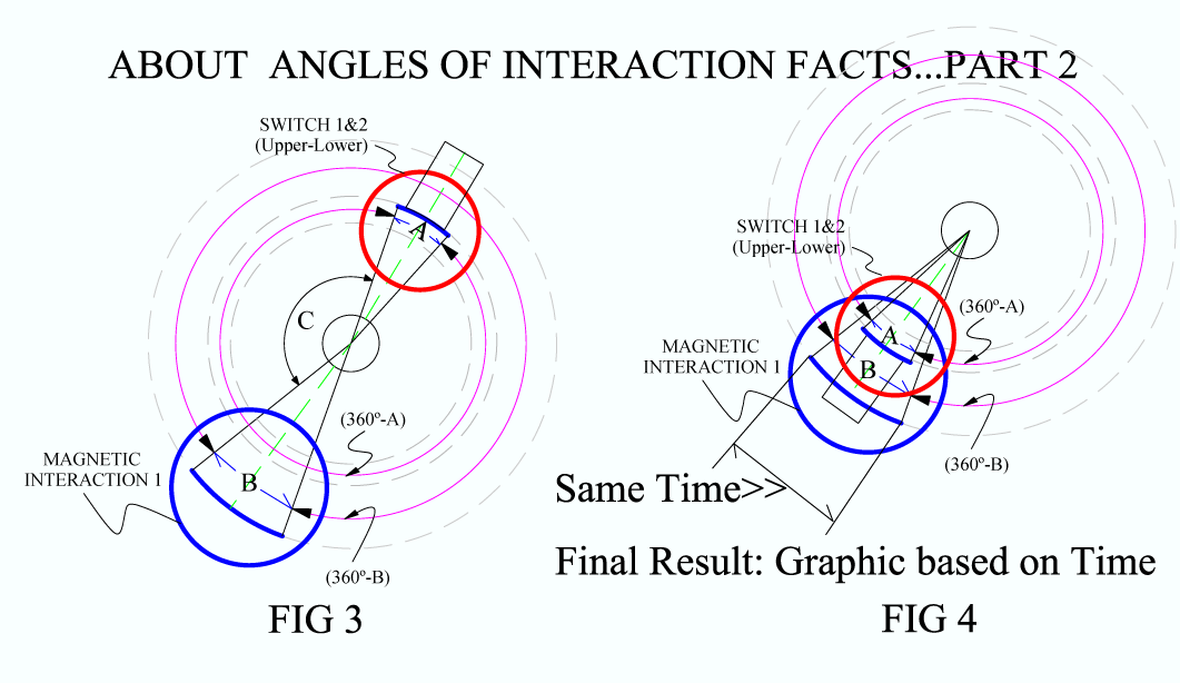 [/IMG]
On FIG 3 This Concept of adding Angles from Switch to Coils is absolutely wrong!!
The only thing that limits/dictates the positioning of our whole Commutating Switch is our Symmetric Motors designs and their Structures, as if brushes could be moved freely, or are completely fixed...and also dictated by our common sense to use less connecting wire length, when winding in order to search for the closest segment that allows Us to be within the structure spec's.
Finally on FIG 4 is the way we must understand the relation between Switching and Magnetic Interaction Angles, based on Two(2) simple facts:
1- The Fact both interactions take place within the same exact Time.
2- That Always Angle A is going to be smaller than Angle B (A < B).
Concluding here, I tell You that, regardless of the Switch positioning, the MAIN part that we must be sure off, check and re-check... are the Magnetic Interactions taking place between Energized Coils and Permanent Stators turn On and Off at the specified angles spec's displayed here by me all along this Thread.
The Switching Circuit, defined by the connecting wires from start coil #1, the Brush and the commutator segment connected to Coil 1 .. could be absolutely anywhere in its circumference as you guys please to do...and please, do not consider this angle for any means, except it just do its job of turning On and Off based on the proper Magnetic Bisecting Angles.
Finally, if We feel comfortable to do so...We could have each segment hooked within the Coils sweep Angle "physically"...just like we are looking in FIG 4, which case I have suggested on previous posts to Mark...asking him if now...would he 'still' add angles.
I know, I am sure off...that this Topic tends to a lot of confusion...I have been trying for the best way to explain/show with the appropriate Graphics this two Interactions relationship taking place...in the best of my ability to keep them as simple as possible.
I have previous experience of several years with Internal Combustion Engines...when it comes to set timing between several turning shafts and sprockets and chains with guide adjustment, etc,etc... where all must be aligned to reach the same exact point in time to fire the correct cylinder chamber at the right, perfect stage...Therefore, I really see this single shafted Machine, as not that complicated when we compare them. However, I can understand for others who do not have even experience with electrical motors... it could bring a lot of confusion.
If You All have any questions about above post, please do not hesitate to make your point, concerns or doubts.
Regards to All
Ufopolitics
EDIT 1:
Now, another thing I must add here, is the fact that after you have decided where to set your switch position...then by moving JUST the Brush, you will be either retarding or advancing the whole process.
So, one thing is to move the WHOLE SWITCH and another completely different is JUST TO MOVE BRUSHES.
The Switch Positioning is something we decide when we are setting our motor structure, before even starting to wind Pair Coils number one (1)Last edited by Ufopolitics; 05-17-2015, 04:34 PM.Leave a comment:
-
Hi UFOOriginally posted by Ufopolitics View Post
I understand your point and agree others should 'render their opinion'. It is disappointing to me that no one has done so.
For many, the timing issue is decided by the OEM brush settings and therefore deciding on the best wind to fit the circumstance and maintain close proximity to the NSB for the 'ON' time.
Timing has also been taken to mean 'tuning' where fine adjustment is achieved to look for the perfect setting.
It might not be obvious to onlookers that the discussion so far has focused on the 'timing' in order to establish the fundamental geometry of the chosen wind and thereby determine if there is any angle left for fine 'tuning'.
I look forward to your next illustration which hopefully covers both aspects and I especially look forward to anyone commenting on the same.
Happy Hunting
markLeave a comment:
-
Hello Mark,Originally posted by HuntingRoss View Post
I understand...that "we" have a disagreement on this subject/topic. However, I hope you understand this 'specific topic' refers to a very important part of Asymmetric Machines, which involves Timing, and as Garry Childers has proven through his latest testings, timing is of the complete essence to achieve a top performance operation on this kind of machines.
Therefore, I am hoping you understand I can not just leave it like this...meaning in a complete "limbo" or abandon it completely...without getting to the bottom of all this controversy that has led to so much fuel to fire the delusional guy on the Hijacked Thread from this one.
So, I took my time (once again) to render some CAD work where I will be posting to the whole Thread...so, please, since we have 'no agreement here'...allow others to render their opinion.
Appreciate that!
Sincerely
UfopoliticsLeave a comment:
-
As agreed UFO, we both have nothing further to add to this particular topic.Originally posted by Ufopolitics View Post
We will have to respectfully disagree.
Happy Hunting
markLeave a comment:
-
Mark, I have to start from the very beginning...Originally posted by HuntingRoss View Post
In your whole response, you deleted the essential part from my previous post:The coils are energised. The shaft with the commutator and the coils, all together, move from connection to disconnection. I understand that. The quantity of that movement is described by the width of the commutator segment plus the width of the brush. They all move together that distance together. And those coil bisectors (pairs and groups) move that distance because they all move together.
Originally posted by Ufopolitics View Post
Mark, I do not need to make pieces out of cardboard...I have 3D Animated CAD Software, transparencies, exotic materials, illuminations, textures etc...it all runs within the same time track...there is absolutely nothing better than this CAD and the Real Model to work on.
Respectfully
UfopoliticsLeave a comment:
-
I truly do understand the mechanics of this operation. It pains me that with all that has been written and drawn on this topic we can not come to understand each other.Originally posted by Ufopolitics View Post
Your comment above is agreeing with me, yet you think I still don't understand.
The coils are energised. The shaft with the commutator and the coils, all together, move from connection to disconnection. I understand that. The quantity of that movement is described by the width of the commutator segment plus the width of the brush. They all move together that distance together. And those coil bisectors (pairs and groups) move that distance because they all move together.
Originally posted by Ufopolitics View PostI agree that there is no more mileage in discussing this point. It seems neither of us are convinced by the others persuasion.Originally posted by Ufopolitics View Post
Correct. It wasn't as clear as it could be. In the context it seemed OK. Being I was talking about the connection to disconnection. If that confused anyone, apologies for that.Originally posted by Ufopolitics View Post
Keep Hunting
markLeave a comment:
-
Above you wrote "connected commutator"...but, connected comm. what?...segment?...or whole comm.?...think you missed the word right?your connected comm has to sweep approximately .
Related to Sampojo...please, do not tell him to add both angles Mark...he is enough confused here, because of previous attacks from this delusional guy...Let allow him to answer my previous post addressed to him first, to see if he understood everything I wrote....and if so...I rather wait to see His results after he test his ten pole motor.
Sincerely
UfopoliticsLast edited by Ufopolitics; 05-16-2015, 09:18 PM.Leave a comment:
-
Just for clarity. I have no argument with Sam or his motor.Originally posted by Ufopolitics View Post
My involvement on this specific topic is to tidy up unfinished business relating to incorrect comments relating to 4 pole pairs pertaining to one of my historic CAD schematics.
There has been to date, a robust discussion on the subject. And I'm certainly not 'falling out' with anyone over the subject.
In fact. With my last post on this subject, if this doesn't settle the matter there is no reason to go any further with it. It can not be put any simpler.
Happy Hunting
markLeave a comment:
-
[IMG]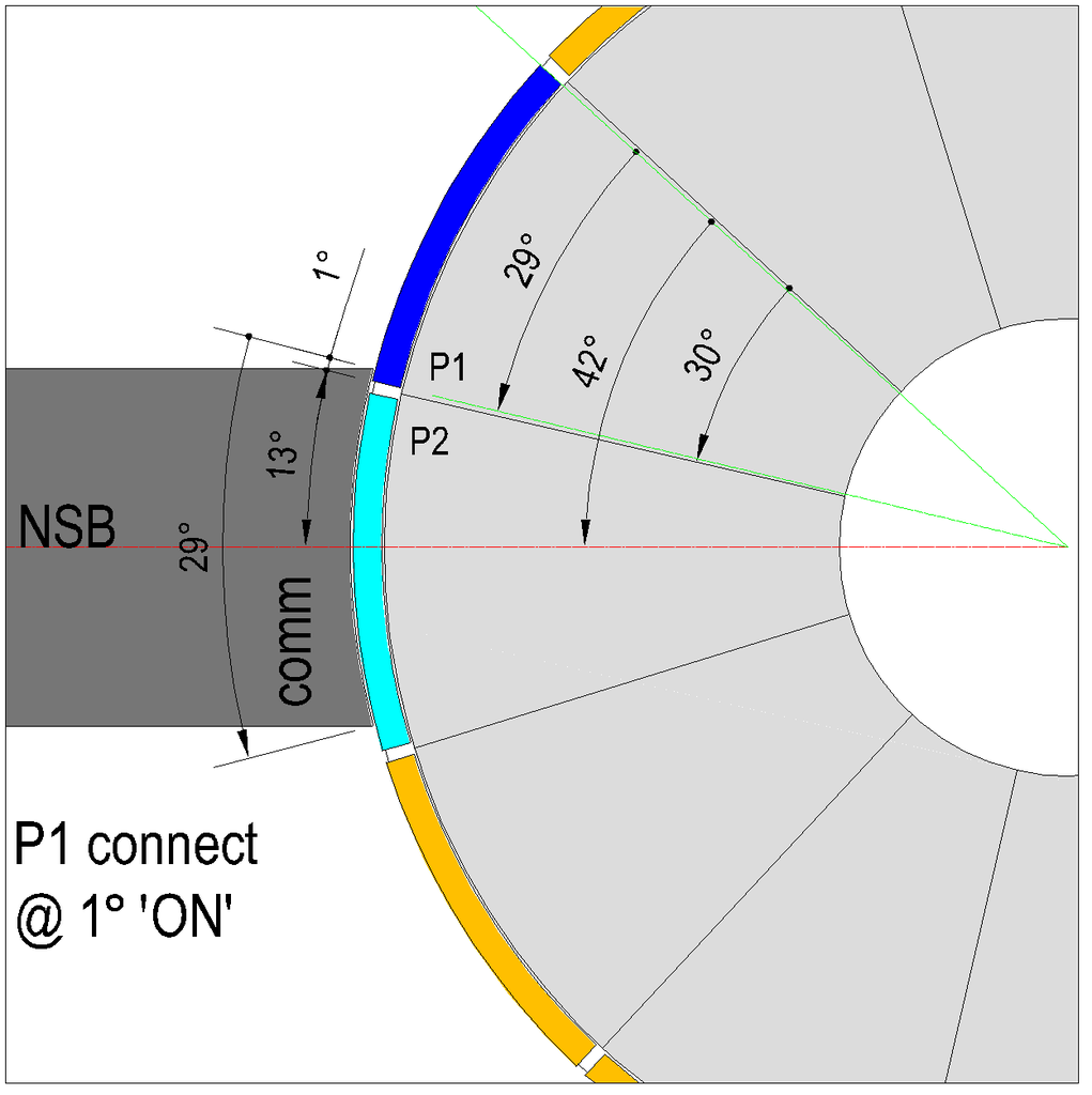 [/IMG]
Image 1 - P1 connecting.
[IMG]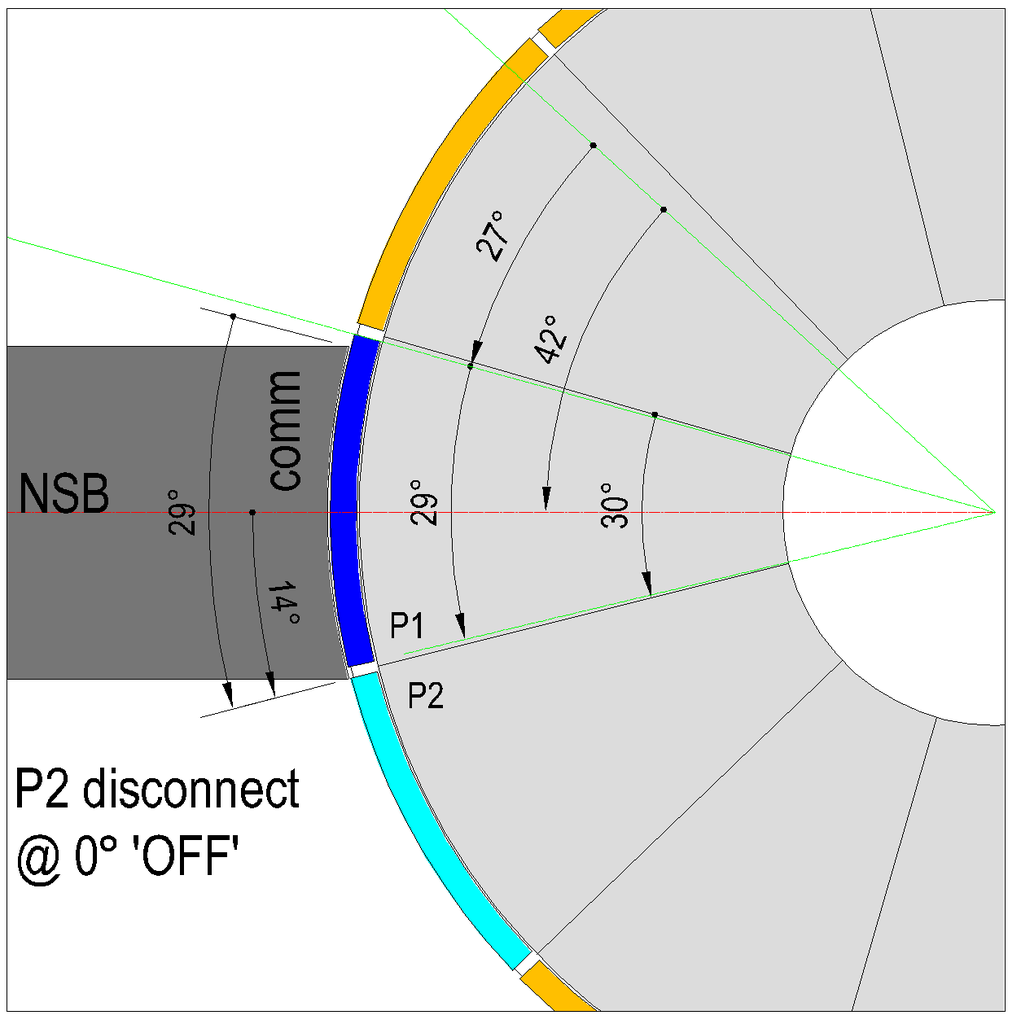 [/IMG]
Image 2 - P2 disconnecting.
[IMG]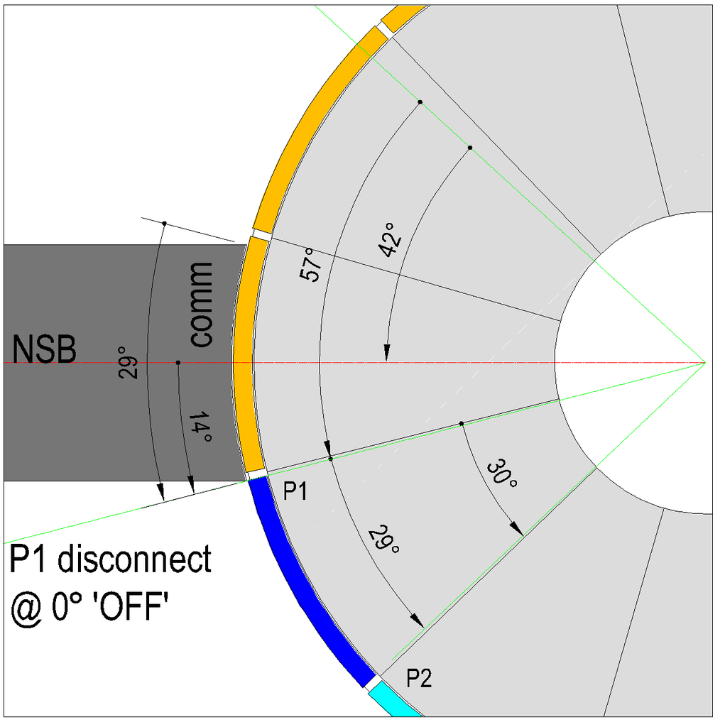 Image 1.Image 2.Image 3.
Leave a comment:
-
Originally posted by sampojo View PostWhat you really would have to make sure...(and this is the most important part) is about deciding between four pole or three poles coils...I suggested the four poles because it will deliver a much faster motor than the three pole coils...and the only way to find out if the four will work...is to wind two adjacent coils (C1-C2) and "mechanically" hand check if disconnection takes place from C2 before it reaches South Stator Bisector....that's all!...if it don't...then go for the three pole coils...simple enough?my brushes are about 3/4's the width of the comm segments.
Another thing that I suggest is to try position of your whole switch, meaning the contacting segments from commutator, the wires to connect to them and Brush... WITHIN the Angle between your C1 Bisector to C2 Bisector. This way you would be doing each 'switching' within each interaction magnetic angle...so no adding, no subtracting absolutely nothing from switching sweeping angle...because both angles (magnetic interaction plus switch sweep angle) would be contained within each others. In very simple description...use the CENTER Commutator segment for each Coil total number of poles (3 or 4)...as long as you could bring brush as well there, in order to establish contact related to stator bisectors.
I don't blame you to be confused and still not finding out the point of all this arguments up to now...about your unique creation...I haven't had time to digest your discussions here and previously, but in the end, is it an analysis on whether there is a potential for the "sweet spot"?
Thank you for all these analyses, as I plan my next moves...
First Midaz invaded this Thread with all his BS...
Then join the arguments Mr. Hunting Ross...
Plus all my other added comments related to the flames ...more CAD's and so much screaming...
Sorry about all this explosion about your ten pole...
I bet you never thought it would be that "famous"!!...
Hey, Sam, thanks!...yeap, it wouldn't happen (losing heart here) just because I have such a powerful card under my sleeve, my friend...that it makes me so sure about everything I am sharing here...PS: Ufo, my personal thanks for not losing heart in the tough situations we can find ourselves in dealing in public and finding the perseverance and dedication to share your engineering discoveries and to continue to help us...
Anyways...let me know if now you've got everything above clearer or not...please do not hesitate to say it out loud!
Your ten pole four stator is now the "Prima Dona" of the show...
Kind regards
UfopoliticsLast edited by Ufopolitics; 05-16-2015, 03:15 PM.Leave a comment:
-
Re: Post 7729 quad 10 pole analysis
Originally posted by HuntingRoss p7729 View PostUfo has remarked on the uniqueness of this design. Another way of saying they dont usually combine 10 poles with quad stators, and maybe for good reason, after all it is a product of my imaginationIf Sam can confirm the brush width then we will know for certain what is achievable with this motor.
Happy Hunting
mark Seems to run pretty nice though, if I don't say so myself!
If it helps to find out if this design has any inherent good qualities, my brushes are about 3/4's the width of the comm segments.
I haven't had time to digest your discussions here and previously, but in the end, is it an analysis on whether there is a potential for the "sweet spot"?
Thank you for all these analyses, as I plan my next moves...
PS: Ufo, my personal thanks for not losing heart in the tough situations we can find ourselves in dealing in public and finding the perseverance and dedication to share your engineering discoveries and to continue to help us...Last edited by sampojo; 05-16-2015, 04:57 AM.Leave a comment:
-
Hi UFOOriginally posted by Ufopolitics View Post
It is good to see you back working on your new motor. Thank you for all of
your efforts getting you ideas out into the public domain. A small note
on the trolls, these people want a free lunch, don't let them take yours
It's show time for you and personally I am looking forward to better things.
There are thousands of us and we all see how these trolls worm their
way in twisting everything around. Take no prisoners, don't pet the trolls
You are the best there is, thanks to all of the other guys too, I won't
name them ALL, you know who you are, standing with UFO.
We are with you UFO.
MikeyLeave a comment:


Leave a comment: