 Tweet
Tweet
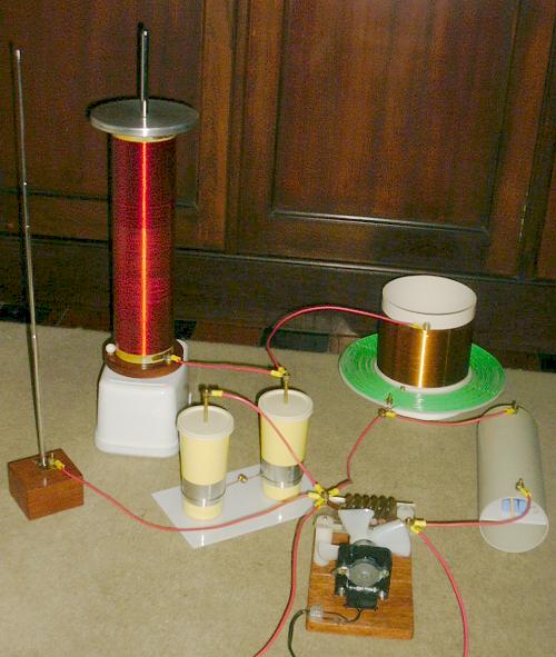
I see so the secondary is wrapped around the "fence like structure" right next to him and the primary is wrapped around the bigger but lower fence like structure in the backround ?
I remember Eric Dollard said that winding the coils on a solid form is bad and a slat type structure should be used. And that the secondary should be as round as it is high. Hmmm cool.
I will just wind another tower type coil the same as what I have and install some sphere's or toroid dome's while I read some more of this thread. I'll also try to mount the primary on a frame.
Then I will try some things wirelessly.
Cheers


Comment