Announcement

Collapse
No announcement yet.

Lockridge Device - Peter Lindemann

Collapse
X
 
  • Filter
  • Time
  • Show
Clear All
new posts

  • Blargus
    replied
    Originally posted by john_g View Post
    Hi Mike

    I'm surprised that the windings are not done to form poles - that could be the way it's meant to be, plus the seem commutators offset. Do you have a winding diagram you can post up?

    Regards

    John
    Hi John,

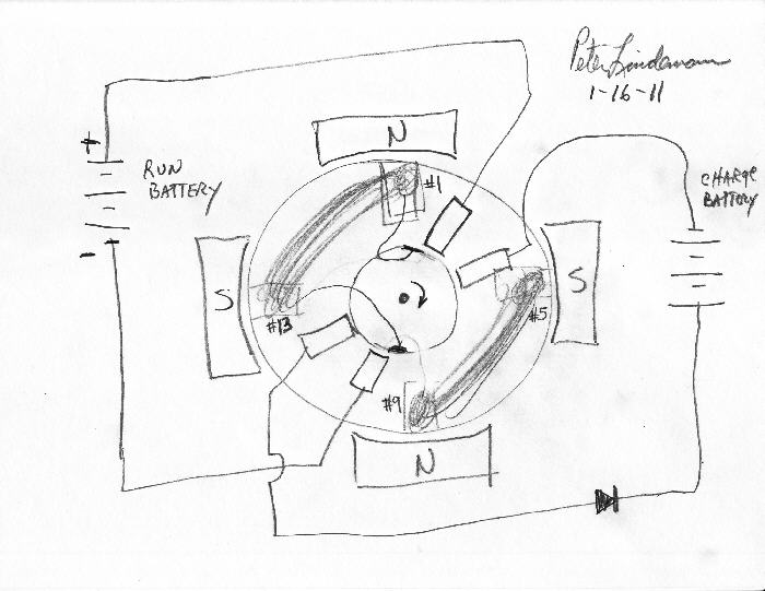
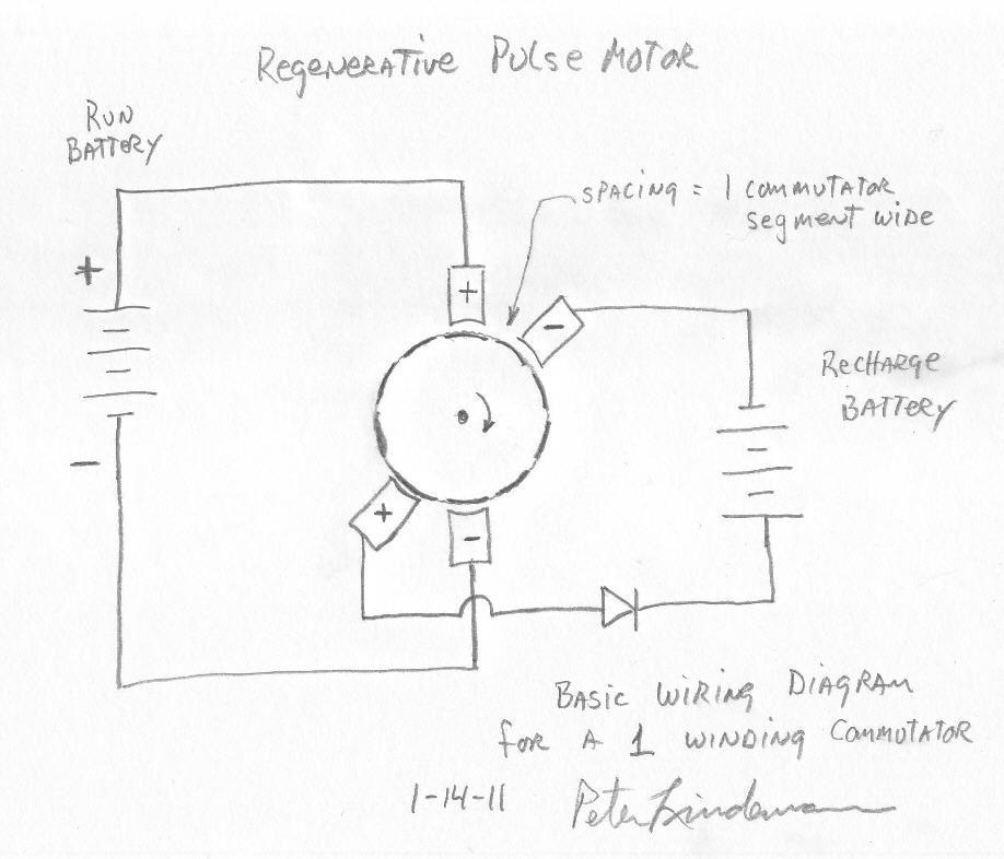
    Well I wound it like Peter Lindemann says earlier in this thread only I spaced the second set of commutator brushes slightly less than 1 commutator segment as per a suggestion that he said would be okay. I've never wound a motor before but it does spin a bit with torque, the problem I'm having is that it just blocks itself when it goes around a half turn, it seems when the commutator segments with the wire ends touch the power on the half turn:

    "Starting at the commutator side, lay your wire into slot #1. Coming out of Slot #1, lay the wire along the back edge of the rotor until you get to slot #5. Then enter slot #5 and come back to the commutator side again. Then go over to slot #9 and lay the wire down slot #9 and come out on the back side again. Then go over to slot #13 and come back over to the commutator side. Then, on to slot #1 again.... around in that pattern until the slots are filled. This is for a 16 slot rotor. The ends of the wires will terminate on two commutator segments that are 180* away from each other when the wire in the slots are sitting in the middle of the stator poles.Hopefully, you and everyone else can understand this. The commutator section is just arriving at the brush when the windings are in the middle of the magnetic fields. The windings on the back side of the rotor cross from #1 to #5 and from #9 to #13, assuming a 16 slot rotor.

    I hope this clears this up, once and for all.

    Peter"


    Thanks!

    Mike

    Leave a comment:


  • john_g
    replied
    Originally posted by Blargus View Post
    Hi guys,

    Matthew Jones is going to help me with this but I wanted to ask also--I put together this zig zag wound regenerative motor with the MY1016 scooter motor and 18 AWG windings. It goes a partial turn or one turn then it reverses itself and stops. My guess is that the magnet field from the windings are clashing with the permanent magnets when the rotor turns 1/2 way. But I'm not sure what to do about it or what's causing it. I know my winding is probably not great but is this the problem? Wondering if anyone can help. Here are some photos, thanks!

    Mike Swanson

    ImageShack Album - 17 images
    Hi Mike

    I'm surprised that the windings are not done to form poles - that could be the way it's meant to be, plus the seem commutators offset. Do you have a winding diagram you can post up?

    Regards

    John

    Leave a comment:


  • Blargus
    replied
    Hi guys,

    Matthew Jones is going to help me with this but I wanted to ask also--I put together this zig zag wound regenerative motor with the MY1016 scooter motor and 18 AWG windings. It goes a partial turn or one turn then it reverses itself and stops. My guess is that the magnet field from the windings are clashing with the permanent magnets when the rotor turns 1/2 way. But I'm not sure what to do about it or what's causing it. I know my winding is probably not great but is this the problem? Wondering if anyone can help. Here are some photos, thanks!

    Mike Swanson

    ImageShack Album - 17 images

    Leave a comment:


  • Robert49
    replied
    Hi guys.

    I'm working on a new motor design which is why I have'nt posted lately.

    I just donated $25 to help Eric Dollard.
    Tesla Round 2, The Mission of Eric Dollard | Indiegogo
    This is one guy who gave his life to advance free energy via Tesla's teachings.

    If any of you can help, please do.
    Thanks


    Robert

    Leave a comment:


  • mbrownn
    replied
    All three, I have come to the conclusion that the only way to get this info out is to do that. put it out there.

    Hopefully I will be able to make a little on it but if not, I don't care. Hopefully I might even get some credit too but that isn't what matters. Don't get me wrong I could use the money but as long as I have a roof over my head and can feed my family that is all that matters.

    Leave a comment:


  • relgub
    replied
    Originally posted by mbrownn View Post
    ... I believe if we can get it working it will win the minds of science.
    HI mbrownn.

    If you get a working OU device what are your plans?
    Will you open source it, produce it and sell it?

    I know it is too early to think about it.
    I just want to know your ideas.

    Leave a comment:


  • mbrownn
    replied
    Hi paul,

    I have tried switching with a relay in the past because I like the abrupt switch but unfortunately it is difficult to get the frequency and they do not last long. When we get around to commutative switching as in the original lockridge it will be a lot better.

    There is no reason why this cannot be done with modern electronics instead of a commutator but I expect we will have some issues burning semi conductors out on the way.

    At the moment, I am fairly sure of the motor coil and generator coil configuration, I am fairly sure of the armature too but we have to eliminate all other possibilities just in case something comes up with other configurations. As it is, something has come up with a lap wound armature and we are testing it. There are a few possibilities for the recovery circuit and a few for the trifilar coil and capacitor but we are narrowing it down.

    The thing is it wont work without all the parts being tuned. If someone has a perfect motor generator but the trifilar isn't right it still wont work. If the device was 100% efficient the COP would be greater than 8 but we know that the universal motor part is around 35% efficient and there are other losses too such as a cap being 50% efficient. Overall I am expecting around 130% or less when we have everything configured. I figure it will be running at about 800 to 1.2kw with an output of around 250 to 300w and it wont run for many hours without needing new brushes.

    No this isn't going to be the ultimate device but I believe if we can get it working it will win the minds of science.

    Leave a comment:


  • pault
    replied
    unmodified motor

    The motor I'm using is a 2-pole universal (probably from a hand drill).

    Here's a scope shot of the 400VDC spikes being generated in the motor before I modified the motor. The motor was being pulsed as above.

    The 2nd pic is that of the sparks inside the relay.
    Attached Files

    Leave a comment:


  • pault
    replied
    PWM circuit

    This is the PWM circuit I used.

    Pulse Width Modulation - Electronics in Meccano

    Instead of the TIP31C, I used a TIP122.

    I replaced the M (motor) with a 12V relay.

    The relay contacts switched 24VDC into the universal motor (unmodified and modified).

    Given that there are 400++V spikes being generated (at 12VDC, 24VDC and 36VDC pulses), it might be a while before I find something solid state to replace the relay...

    pt

    Leave a comment:


  • mbrownn
    replied
    Hi Paul, as you are using a 2 pole motor you might not get what we have. The device is simple but the interactions are complex.

    We have a great increase in voltage on the unconnected winding.

    what your trace does show is there is a transformer action. Put a low impedance load on the disconnected coil and shorten your pulses by 2/3rds.

    better still get a four pole universal motor and ill tell you what to do and the basics of this is in my previous post. We need replicators to confirm results.

    Remember this is just the motor/generator so don't expect great efficiencies yet. There is little BEMF on the motor so it draws high current.

    We are in a process of elimination at this stage testing different armatures to see what happens and our results were better than I expected.

    Take a close look at the FEMM drawing,there are a lot of clues in it. The red coils are the input and the green is the output. if the other two white coils are used' the 3 o'clock is powered and the six o'clock is an output. If you don't split the case you will only be able to use 2 stator coils and it will not perform as well. the black boxes represent the location of the carbon brushes.

    With my design we have transformer and generator action in our output coils but I have not seen a scope trace yet.

    Leave a comment:


  • pault
    replied
    2-pole universal motor, bottom coil disconnected.

    Pulsed at about 1000 RPM (16Hz) using 555's, 33% duty cycle and a relay. If I have time, I'll post all of the details to EF tomorrow. Otherwise, when I return in a week or so (remind me :-).

    Top trace is across the modified motor. 50V/div.

    Middle trace across the 2nd coil (disconnected, acting in transformer mode). 5V/div

    Bottom trace is the dual-555 driver circuit hitting a relay, switching 24VDC pulses across the motor (major sparking across the contacts of the relay).

    400V spikes on the motor side. 10X less on the 2nd coil side.

    I also did scope shots before modifying the motor and not much was different (400V spikes). The results were essentially the same as the top trace. (The 400V spikes are barely visible, but they are there).

    pt
    Attached Files

    Leave a comment:


  • mbrownn
    replied
    This is about making the motor/generator part of the lockridge

    Its quite simple really but making it happen takes a little work. You will need an AC or half way rectified AC or a pulsed DC supply for it to work although in the final device it will be pulsed DC

    You need a 4 pole universal motor, these usually have four brushes on the armature but we will only use twoat this stage.

    The 3 o'clock, 9 o'clock coils and the armature are powered in series through the brushes at the 3 o'clock and 9 o'clock positions. The motor is in magnetic lock when operated this way and will not turn.

    Now take the 12 o'clock and 6 o'clock coils and connect them to a low resistance load. the motor may begin to turn
    To improve motoring performance the 12 and 6 o'clock coils may have to be advanced or retarded to find the Ideal position.

    A varying supply has to be used or you will not get transformer action. The transformer action powers the 12 an 6 o'clock coils giving an electrical output

    As the motor is in magnetic lock, no BEMF is generated, even when the motor is turning little BEMF can be generated.

    The motoring force is caused by the flux being compressed at one side of the 12 and 6 o'clock coils.

    The motoring force is not good at this point as al the coils are interacting with each other and the flux is being shorted

    To further improve motoring action we have to split the case length ways, just as in the lockridge device at the 1.30 and 7.30 positions and with fine tuning of the position of the 12 and 6 o'clock coils good motoring action takes place.

    As the motor is now turning BEMF or forward generated current is occurring in the 12 and 6 o'clock coils.

    An amplification of voltage occurs in the output.

    See drawing of magnetic circuit
    Attached Files

    Leave a comment:


  • john_g
    replied
    Originally posted by mbrownn View Post
    The slow acceleration may be significant
    I think it is significant also - seems to me that the machine is only just about generating/reusing energy to just keep itself going, making only a very small energy gain with each revolution.

    Leave a comment:


  • mbrownn
    replied
    The slow acceleration may be significant

    Leave a comment:


  • Robert49
    replied
    Hi guys.

    I saw my friend Henry this Sunday and we talked a bit about the self-running generator "Lockridge device".
    You have to remember that he was born in 1938 so he was only eight years old in 1945.
    They had these in underground bunkers just for lighting.
    He did not interact with the machine but he remembers clearly that the device was started by hand with a pull cord. Then the device would accelerate slowly , he does'nt know the speed but he says it was running possibly between 1000 to 3000 rpm and would hear a clicking sound , not fast but steady.Then they switched the lights on.

    Not a lot of help but he confirms "it did work"

    Wish I could help more.

    Robert
    Last edited by Robert49; 12-10-2012, 11:48 PM. Reason: forgot something

    Leave a comment:

Working...
X