back to back observations
I tried several back-to-back experiments.
1) My modified motor coupled to an unmodified motor of the same kind acting as a generator. At 36V, the combination spun at about the sweet spot for efficiency for the modified motor (3750 RPM). The generator output was attached via a FWBR (UF4007's) to a 3300uF cap (400V). The cap charged to 12.9V and held.
E = 0.5 x C x V^2 = 0.5 x 0.0033 x 12.9^2 = 0.2746J
2) Same setup, but with the recovery brush pushed through a FWBR (UF4007's) ganged in parallel to the generator FWBR output, into the 3300uF cap. The cap charged to 20.78V. E=0.7125J.
3) Using thee combined E from (2), I calculated the capacitance which should have resulted in 36V of charge. C = 2 x E / V^2 = (2 x 0.7125) / 36^2 = 1100uF. I replaced the output cap with a 1,100uF cap (35V) and ran the machine.
The cap charged only to 20.94V.
Not what I expected. Comments?
4) I removed the stock armature from the generator and replaced it with my 1st modified armature (1 coil, 18awg, commutators lathed after previous abuse). The 1100 uF cap charged very quickly to 19.3V, i.e. almost as high as that for the unmodified armature with a full set of windings. The combination produced immense vibration, and I terminated the run quickly. Clearly, any further investigation of this kind of combination requires a flywheel to damp out the mechanical imbalances.
pt
-
shorting coil
Inspired by Woopy, I did a brief experiment with a shorting coil on my 3pm, reported here:
Yahoo! Groups
400V spikes (on the 'scope, which doesn't even capture half of what's going on), 100V into a 10uF cap in mere moments. More experimentation required...
ptLeave a comment:
-
Self Running Motor
"Soon" goreggie
"It can be built. We are discussing just that in this thread. Read through we are working not wondering."
MattLeave a comment:
-
Watch John's Energy from the Vaccum video and see Peter's lecture video plus do some basic reading and you will find the answers to all your questions. There is no 100% proof that it existed but all the evidence is quite good and there would be no point for all the people who owned one to lie about it.Originally posted by WeThePeople View PostLeave a comment:
-
Wow, ouch.Originally posted by Peter Lindemann View Post
In all of europe, and all the military personal returning to USA,
no one ever smuggled one home to toy with for gosh sakes ?
I thought I read somewhere someone had smuggled one home...
They made these in a factory too, no data about that even ?
This is a sad state of affairs, how do we even know it was real then ?
I'm not trying to be fickle here, but is there any confirmation available ?Leave a comment:
-
Hi mark I got it off of ebay paste, 4700uF 450V Hitachi capacitor TUBE AMP CAP
and it will come up. I paid $29.00 dollars each
On the 4 coils it was wound with one wire but it didn't run on 24 volts.. I think it needed higher voltage so I stopped. Waiting for the new one coil wound hopeful any day ReggieLeave a comment:
-
Hey Reg,
The 4 coil set up should have still worked. If you wound all 4 coils with 1 piece of wire it gets very confusing which way to wind. The first rotor I wound I wanted to wind 4 seperate coils with 1 wire but wasn't sure which way to wind so I just wound 2 seperate coils with 1 wire. All the rest of my rotors were wound with the "zig-zag" method.
Nice Caps! Where did you get them and how much. I cant seem to find a good place to get high voltage high capacity caps at.
Keep us posted.
MarkLeave a comment:
-
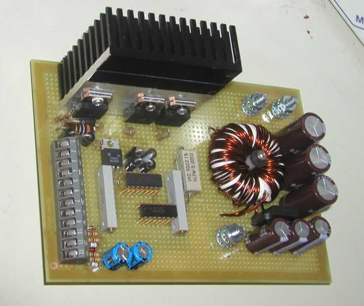
This is the new DC-DC converter used to drive the motor as well as the current control for the absorber. Both are controlled by the computer.
Leave a comment:
-
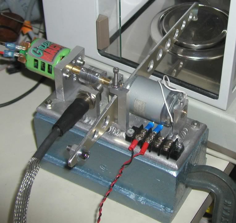
My small dynamometer with a range of less than 2 mNm to over 110mNm.
This dynamometer uses a small DC motor to act as the absorber. The motor to be tested is mechanically linked to the absorber by a series of driveshafts and a coupler. The absorber is mounted in such a way that it is allowed to rotate. An arm is then mounted to the absorber. As load it added to the absorber, torque is created in the arm. The arm pushes downward on a precision balance. A hall type sensor is use to measure the shaft rotation. A computer is then used to control and monitor the dynamometer as well as display the data.
Wiki is a good source if you would like more details about how a dyno like this works.
Dynamometer - Wikipedia, the free encyclopedia
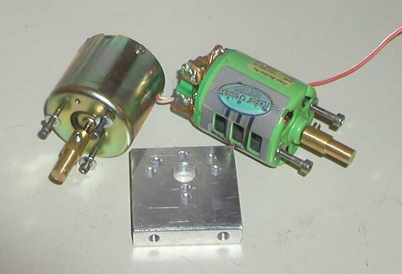
The following shows the two support bearings for the absorber along with the coupler. The coupler will have two small magnets mounted inside.
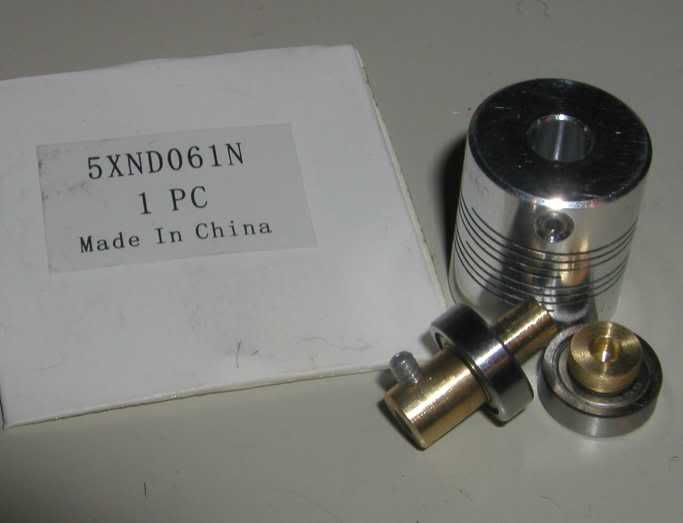
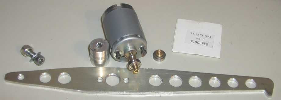
The torque arm, modified coupler with magnets, absorber and the counter balance for the arm.
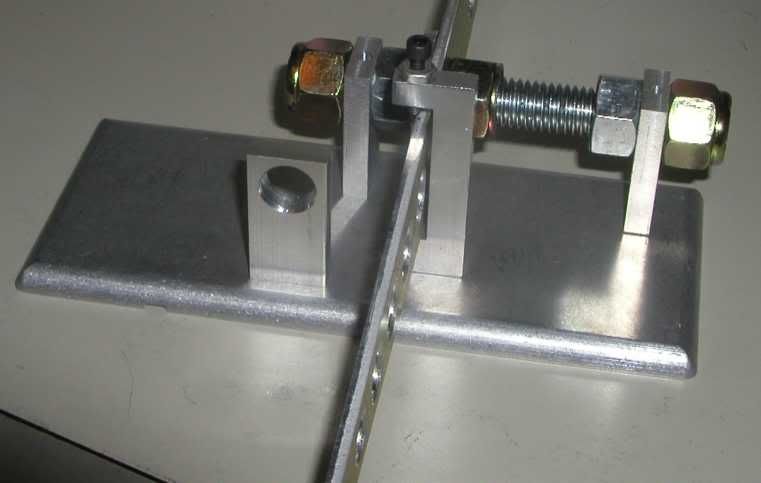
The base with the bearing supports, torque arm limiter and hall sensor mount. The threaded rod holds the bearing supports in place for welding. The bearing holes are undersized and line bored after welding.
These are two of the motors I plan to use to test the dynamometer along with the motor mount. The mount was not welded to the base to allow ease of motor change out. The motor on the left is from a VCR and was used to drive the tape spindle. It is rated for 6V operation and has very low torque. On the right is a hobby motor. It has much higher torque and capable of running at 20,000 RPM.
The dynamometer and balance with the hobby motor installed.
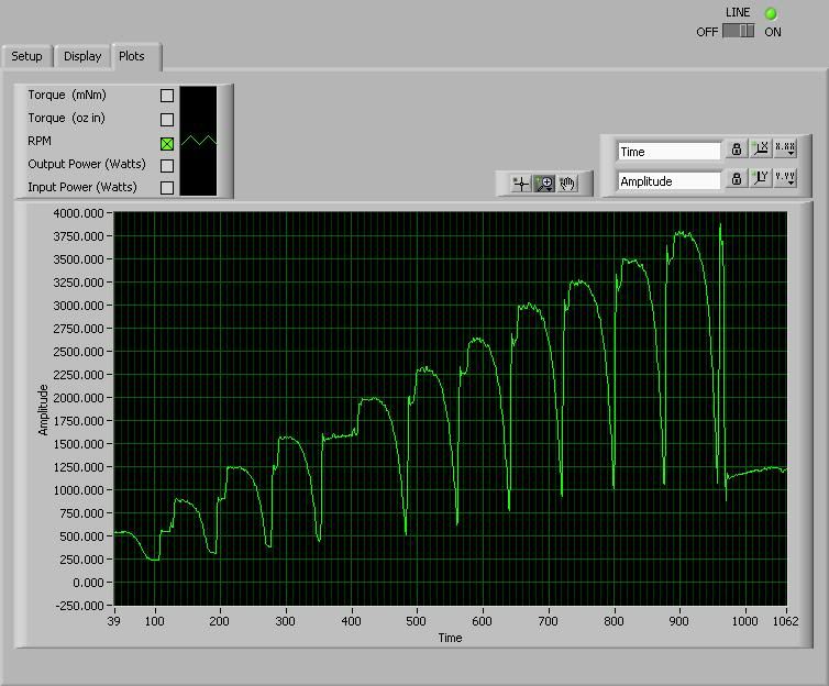
Looking at pulls with the 6V VCR motor. RPM is shown. Motor supply voltage was set to 4V then incremented in 1V steps to 14V.
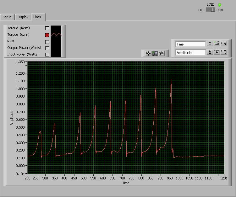
Looking at torque for the same pulls.
Here the data is overlaid to show each pull. Notice that the shaft speed increases at the end of each consecutive run as the voltage increase. The system is not yet closed loop.
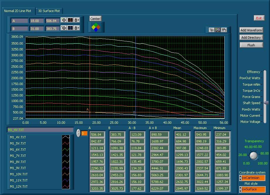
Showing motor output power in Watts for all 11 pulls.
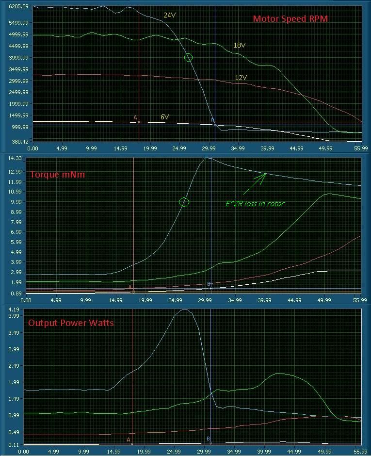
The 6V VCR motor was ran again at 6, 12, 18 and 24V. The following set of plots show the effects on the speed, torque and output power.
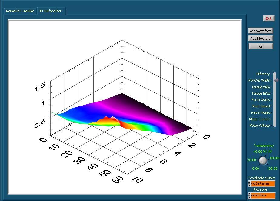
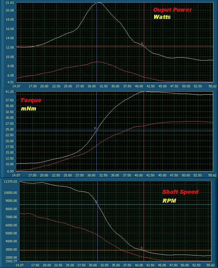
This data was taken from the green hobby motor. The ratio of output to input power shows that the motor is most efficient in the area left of the peak output power. This matches with the manufactures data. Currently I have not pushed this motor to its limits because of the vibration at these higher shaft speeds.
If your considering building your own dynamometer, I have created a list of my concerns with this setup.
1) Pick a better absorber, or make one from scratch. The rear support is just not stable enough. I had some ideas on what I wanted to measure so I sorted motors to find something in this range. The motor's bearings, the fact it has brushes, balance, etc all make this a bad idea. Designing something to do the job right would be better time spent.
2) Use better construction practices. While I knew the aluminum would warp during welding, I had left the bearing holes 10 under. After welding, I then borded them with a reamer. This is fine, but the small amount of warp in the base causes drag when it is clamped to a flat surface. IMO, don't weld. Machine the bearing support from one piece and then bolt it to the base.
3) Use C -clips to hold the bearings. The setscrews cause the bearings to distort and add drag. It does not take much.
4) Make sure that the bearings you use are up to the task. This dyno was made from scraps. This included the bearings that came from a small stepper motor I had tore apart. This was a poor choice.
5) With a 6" torque arm, make sure the shafts are near perfect. Any errors here are just multiplied by the arm length.
6) Figure out a way to balance the rotating parts. I have some ideas, but nothing proven.
7) I had tried to keep the rotating weight down. A flywheel may help to reduce vibrations.
8) The coil type of coupler I used may not be the best choice. Any missalinment adds drag.
9) Design a better mount for the test motor. The block is OK, but imagine drilling holes for all your motors. Maybe something with micrometers to fine tune the XY&Z.
10) Think about adding a closed loop control system. This system would have it, but I think it has enough problems that it does not warrent any more time spent on it.
11) The power supplies compensation lines need to be connected to the motor and the cable sizes need to be increased.
12) Use a larger heat sink for the absorber's FET drive.
13) Come up with some sort of air duct system for the motor and absorber as well.Leave a comment:
-
Ah. Something that is "obvious" and unspoken by people who have rewound motors in the past.Originally posted by Robbush View Post
Keep the windings tight.
If the windings don't look tight enough, unwind and start again.
I re-started my windings a few times, but I didn't record the fact (because it seemed obvious) ...
It doesn't need to melt, it just needs to become less stable due to heat.The motor was still warm when I took it apart but no signs of any melting.
My commutators don't require any soldering. Just crimping.
If you do achieve more even crossovers, please report the details.I have some smaller wire 24 or 26 ga. , will rewind it (differently- more even crossovers) and see if I can get the power up and the current down.
More windings = higher resistance = lower current draw for the same power (V x I).
My friend lathed my warped commuator. We found that high lathing speed was bad and resulted in a very rough finish.But first... to the lathe to clean up the commutator. Will post pics.
rawbush
Copper is soft. Use slow speed. Then, when done, use progressively finer grades of sandpaper to finish up.
And make sure that there are no shavings caught in between the commutators, shorting them out.
ptLast edited by pault; 03-09-2011, 04:49 AM.Leave a comment:
-
I think vibration and speed led to the wires coming off the commutator. The motor was still warm when I took it apart but no signs of any melting. I have some smaller wire 24 or 26 ga. , will rewind it (differently- more even crossovers) and see if I can get the power up and the current down. But first... to the lathe to clean up the commutator. Will post pics.Originally posted by pault View Post
rawbushLeave a comment:
-
Peter did not prescribe any overlap in the recovery brushes. He wanted them "close" to catch the back spike as soon as possible, but no overlap (overlap would drain power from the run).Originally posted by Robbush View Post
48.8V x 5A = 244W. I think you might have overloaded it. My current winding is running below 2A, more like 1A.
Did the solder look like it broke, or did it just melt (a bit) and fatigue from the power?
How warm / hot was the motor? (Watch out, I gave myself a huge blister once, when "testing" the heat of a slot-car motor).
When my recovery brushes weren't working correctly, I could see sparks flying in the hole through which the wires came out of the case.
In my first attempt, I used 18awg wire (only 30 turns) and got the current up to 8A before the thing deformed one of the run commutators. I had to get it lathed to put it back into line. My current attempt is using 90 turns of 23awg (iirc, notes not in front of me) and draws no more than 2A.
ptLeave a comment:
-
The dyno I built is like what Peter used in his first video, except mine has the spring scales mounted and one is adjustable to keep a load steady, much like you explained. In the first test I applied braking till the amp meter got to 5 amps then set the stop (nut on bolt) so all the other readings could be taken.
Also got the motor apart to see what went wrong- there are burnt commutator sections, the ones the coil connects to. I also found that three of the four coil connections to the commutator had broken off(solder), this is why motor stopped. My recovery brushes have no over lap in timing and I am wondering if this is causing the burnt sections? Or could the poor connections ( till they broke) be the cause? Also the run brushes had black areas in them too, but not the recovery. Any ideas? Should I rearrange the brush set up to have a little overlap? Peace
rawbushLast edited by Robbush; 03-08-2011, 11:04 PM.Leave a comment:
-
poor man dynamometer
For the benefit of members who want to consider their options in building a dynamometer, Prony brake, etc., here is what I came up with:
I built a dynamometer much like that in Peter's vid #1, except I built it upside down.
I placed an "accurate" digital kitchen scale on the floor.
On top of the scale, I placed a jug of water and measured its full weight.
I attached a string (actually 2 strands from a CAT5 wire) to the jug's handle and attached the other end to a spring.
The spring is connected to a short piece of leather (shoelace snipped from a pair of worn-out Dockers), whose other end is connected to another spring which is secured to the workbench.
I got a small brass bushing with a slot machined into it and set-screwed it to the shaft of the motor. I measured the diameter of the slot with calipers and calculated its circumference (pi X d).
I created a "ratcheting" pulley by standing a (rectangular) bench vise on its end (sufficiently C-clamped to the workbench). To the movable end of the vise, I attached a rod and a pulley (from a lego set).
The leather shoelace then rests on the brass bushing, tethered to the bench by one spring (on the "push" side of the motor shaft rotation - i.e. 0 weight), and the "pull" side of the leather attached to the string going over the pulley down to the weight on the floor.
bolt -> spring -> leather -> spring -> string -> weight on scale
leather resting over brass motor shaft, rotating as to pull on the weight side of the leather
vise+pulley on string
To take measurements, I run the motor, take all 4 readings. I read:
V with a multimeter
A with a panel meter
speed with an oscilloscope attached to the recovery output - RPS = 1 / (msec between pulses X 2) because there are two pulses for each revolution
weight = original-weight-of-water - current-reading (i.e. the weight actually applied to motor shaft is the difference between the original weight and the slightly lifted weight).
To ratchet up to another (higher) load, I give the vise handle a few turns, lifting the pulley slightly higher and pulling more weight off of the scale.
I could run a wide range of loads by starting with different quantities of water in the jug. As I reviewed my interim results, I could see if I needed to examine a particular zone of loads more closely.
Even if this method is not good enough to give me exact, absolute HP readings, it appears to be repeatable enough to get relative readings for this motor and to find it's sweet spot.
My motor at 36V, free runs at about 4,800 RPM and is most efficient (70%-80%) with 900-1000g load running around 3,800 RPM
ptLeave a comment:
Leave a comment: