Announcement

Collapse
No announcement yet.

Donald Smith Devices too good to be true

Collapse
X
 
  • Filter
  • Time
  • Show
Clear All
new posts

  • Originally posted by clarence View Post
    Hello Soundiceuk, clarence here- just exactly how does a person go about receiving any of the links information concerning Don Smith files. and what does a # sterling amount to in USA?
    mike, onward! thanks.
    In paypal, you can say that you want the recipient to to receive a specified currency.
    Just pick pounds and the amount.
    Need to check the box, that you will be paying for the transaction as well, otherwise 1 pound minus paypal fee will be transferred.
    Comment


    • nice!

      Originally posted by Utopia Now View Post
      Hallo everyone about 3Wave forms on Scoop. < and <> and > ( Video and Schematic on video )

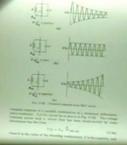
      Here my experiments about finding Trumpet < wave form and Whale <> wave form.
      In my set up I have them both and they are different. (And I also have a normal Ringing > wave form).

      Video1 Trompet wave and Video2 Ringing and Whale wave.


      The Trumpet wave form is at the end of the NST (at the High Voltage Coil )
      I think: the 30kHz HV is filling the capacitor till breakdown voltage of the surge arrester ( Spark Gap ) and starts again <<<< this happens about 1000 times a second ( 1kHz ) the Spark Gap sound i hear.

      The Normal Ringing wave form is at the L2 CCW coil ( L1 is in the middle of L2 )
      I think: every time L1 gets a hit via the Spark Gap it also hits L2 CCW and you see the Normal Ringing.

      The Whale wave form is at the L2 CW Coil.
      I think: L2 CW is slightly out of tune ( resonance ) with L2 CCW and therefore we get the whale form.
      If I detune it (more) with the variable Cap C3 .. I get more smaller whales instead of one big whale


      L2 CW is 3cm away from L2 CCW ….. L1 is in the middle of L2
      I also move L2 CW closer to L2 CCW to see what happens.

      I think because L2 CW is 3cm away from L2 CCW, loading L2 CW will not influence the input power very much …

      Dons Comment in the 1996 Tesla Film is about a resistor in the middle that along with the capacitor and coil cause the cycling effect … it cuts off and than it cycles back … Does any body know more about this and the resistor .. what and how it should be done .

      This is all just testing and I still have to continue with the rest of Don`s schema possibilitys : Diodes, Capcitors, Earth Grounding , Step Down … inverter … or 50 hz Transformer Capacitor.

      In an earlier different set up I all ready had a 10 watt 12 volt light bulb shining from L2 (40wt input no OU yet) but that was before I found about the diffrent wave forms. ( I did have some form of resonance .. but I didn`t know where and how to messure the wave forms than )

      Now i have to continue experimenting.

      I am very open for advise and suggestions Love to hear tips for schematic on how to continue from here .

      I am also very thankfull for all of your info and help till now … and especially the help that will come in the future.

      Also watch Ingeners Opposite Coils Video

      In the future I will put some info in a new prezi doc.
      I will name it "Ambient TesZeline"
      If you get a free account than you will be able to download and save the doc.
      Hope to get to wonderfull results soon .

      Together we shall Create Wonders

      Utopia Now
      Great work buddy!
      In the beginner's mind, there are many possibilities.
      In the expert's mind there are few.
      -Shunryu Suzuki

      Comment


      • Originally posted by Utopia Now View Post
        Hallo everyone about 3Wave forms on Scoop. < and <> and > ( Video and Schematic on video )

        Here my experiments about finding Trumpet < wave form and Whale <> wave form.
        In my set up I have them both and they are different. (And I also have a normal Ringing > wave form).

        Video1 Trompet wave and Video2 Ringing and Whale wave.


        The Trumpet wave form is at the end of the NST (at the High Voltage Coil )
        I think: the 30kHz HV is filling the capacitor till breakdown voltage of the surge arrester ( Spark Gap ) and starts again <<<< this happens about 1000 times a second ( 1kHz ) the Spark Gap sound i hear.

        The Normal Ringing wave form is at the L2 CCW coil ( L1 is in the middle of L2 )
        I think: every time L1 gets a hit via the Spark Gap it also hits L2 CCW and you see the Normal Ringing.

        The Whale wave form is at the L2 CW Coil.
        I think: L2 CW is slightly out of tune ( resonance ) with L2 CCW and therefore we get the whale form.
        If I detune it (more) with the variable Cap C3 .. I get more smaller whales instead of one big whale


        L2 CW is 3cm away from L2 CCW ….. L1 is in the middle of L2
        I also move L2 CW closer to L2 CCW to see what happens.

        I think because L2 CW is 3cm away from L2 CCW, loading L2 CW will not influence the input power very much …

        Dons Comment in the 1996 Tesla Film is about a resistor in the middle that along with the capacitor and coil cause the cycling effect … it cuts off and than it cycles back … Does any body know more about this and the resistor .. what and how it should be done .

        This is all just testing and I still have to continue with the rest of Don`s schema possibilitys : Diodes, Capcitors, Earth Grounding , Step Down … inverter … or 50 hz Transformer Capacitor.

        In an earlier different set up I all ready had a 10 watt 12 volt light bulb shining from L2 (40wt input no OU yet) but that was before I found about the diffrent wave forms. ( I did have some form of resonance .. but I didn`t know where and how to messure the wave forms than )

        Now i have to continue experimenting.

        I am very open for advise and suggestions Love to hear tips for schematic on how to continue from here .

        I am also very thankfull for all of your info and help till now … and especially the help that will come in the future.

        Also watch Ingeners Opposite Coils Video

        In the future I will put some info in a new prezi doc.
        I will name it "Ambient TesZeline"
        If you get a free account than you will be able to download and save the doc.
        Hope to get to wonderfull results soon .

        Together we shall Create Wonders

        Utopia Now
        Hi utopia now
        Great presentation
        Just 1 question
        i cannot zoom your oscilloscope to see what is the voltage, in video 1,
        at begining and ending the first wave truppet ??

        Comment


        • Originally posted by spark2 View Post
          Hi utopia now
          Great presentation
          Just 1 question
          i cannot zoom your oscilloscope to see what is the voltage, in video 1,
          at begining and ending the first wave truppet ??
          This is what you are looking for start:
          Trumpet waveform - YouTube
          Trumpet Wave Ignition Coil - YouTube

          When using it right in free oscillations, it will end up with building up energy and power amplification.

          Good luck!

          Comment


          • thanks!

            Originally posted by Harvester View Post
            In paypal, you can say that you want the recipient to to receive a specified currency.
            Just pick pounds and the amount.
            Need to check the box, that you will be paying for the transaction as well, otherwise 1 pound minus paypal fee will be transferred.
            hello Harvestor ,
            thanks for your info Sir!

            mike, onward!

            Comment


            • Originally posted by Ganzha View Post
              here is possible schematics
              actually its much different, the schematics are available, Soundiceuk can probably direct you

              there is a yahoo group for Bruce's forum Radiant_Energy
              In the beginner's mind, there are many possibilities.
              In the expert's mind there are few.
              -Shunryu Suzuki

              Comment


              • Trumpet Free Oscilations

                Hallo T1000, Romero UK and Boguslaw Mr Clean and others thanks for your inspiring info and reactions.
                This is what you are looking for start:
                Trumpet waveform - YouTube
                Trumpet Wave Ignition Coil - YouTube
                When using it right in free oscillations, it will end up with building up energy and power amplification.
                Good luck! T1000
                This one I also find very interesting:
                Trumpet Waveform From Plasma Tube

                Hallo Spark2
                Just 1 question
                i cannot zoom your oscilloscope to see what is the voltage, in video1,
                at begining and ending the first wave truppet ??
                The scope was set at 1 volt/div and I used a Testec-HVP-15HF High Voltage Probe 1000/1 50-MHz so that makes it 1000 volt/division .... if I look at the video1 thats about 0,6 div at the beginning of the trumpet wave and 2,7 at the end of the trumpet wave .... makes 600 volt and 2,7 kV.
                In video1 i used a variable spark gap and more input power ... In video2 i used a 600 volt surge arrester

                Hallo Clarence
                I noticed that you didnt show an inductance value for L1 on your schematic.
                L1 is 3,4 uH 6 windings ... in this test set up i did not take care about the lenght of the wires ( 1/4 etc ) ... but i will in the future.

                Utopia Now
                Attached Files

                Comment


                • new vid

                  hey everyone, im trying using magnets to quench the sparkgap to sharpen the off-time, i did notice a more distinct ripping sound compared to the usual fuzz noise.
                  also retuned again, 10nf on L1 and 160nf on L2.
                  Input was 75v at 300ma, and had 13v across the 60 watt xenon car bulb on output, so volts were correct on load.

                  If the bulb was getting less than full wattage, then i think it would not read full 12v on load, but with 13v reading across the 12v load, its most likely completely lit.

                  Then to compare, i hooked up the 50 watt halogen, and it read 12v across the lit bulb as well, telling me the 50 and 60 watt bulbs are fully working with 20-22.5 watts input

                  38 Don Smith Device Project: Magnetic Quenching of Spark- Gap and Some Fine Tuning - YouTube
                  Last edited by mr.clean; 10-19-2012, 10:51 PM.
                  In the beginner's mind, there are many possibilities.
                  In the expert's mind there are few.
                  -Shunryu Suzuki

                  Comment


                  • Hi,

                    Not bad but measurements won't be correct with digital meters. They do not work in this environment correctly at all. The best bet is oscilloscope or analog volt/amp meters in worst case scenario. You have high frequency in place so it is complicated on measurements even on analog meters

                    Another thing to keep in mind: the higher frequency, the less energy is needed to heat bulbs. That applies to induction heater too. This comes from my own observations in multiple experiments.

                    Also about resonance: every time you change load , it affects your resonant point and you need re-tune circuit for that load to be in resonance again. There are methods for autoresonance but that is up to you which one you choose...

                    Hopefully that is usefull bits.

                    Cheers!

                    Comment


                    • Question on auto reasonance

                      Originally posted by T-1000 View Post
                      Hi,

                      Not bad but measurements won't be correct with digital meters. They do not work in this environment correctly at all. The best bet is oscilloscope or analog volt/amp meters in worst case scenario. You have high frequency in place so it is complicated on measurements even on analog meters

                      Another thing to keep in mind: the higher frequency, the less energy is needed to heat bulbs. That applies to induction heater too. This comes from my own observations in multiple experiments.

                      Also about resonance: every time you change load , it affects your resonant point and you need re-tune circuit for that load to be in resonance again. There are methods for autoresonance but that is up to you which one you choose...

                      Hopefully that is usefull bits.

                      Cheers!
                      Hello T-1000,
                      a cheerful and pleasant greeting to you Sir!

                      enjoyed your post and was definitely interested in whatever information you could give on your mention of auto reasonance methods. sounds as something I would need to use in my build circuit.

                      Always enjoy and profit by your good posts Sir.!
                      mike,onward!

                      Comment


                      • Originally posted by T-1000 View Post
                        Hi,

                        Not bad but measurements won't be correct with digital meters. They do not work in this environment correctly at all. The best bet is oscilloscope or analog volt/amp meters in worst case scenario. You have high frequency in place so it is complicated on measurements even on analog meters

                        Another thing to keep in mind: the higher frequency, the less energy is needed to heat bulbs. That applies to induction heater too. This comes from my own observations in multiple experiments.

                        Also about resonance: every time you change load , it affects your resonant point and you need re-tune circuit for that load to be in resonance again. There are methods for autoresonance but that is up to you which one you choose...

                        Hopefully that is usefull bits.

                        Cheers!
                        i fully agree, but... it was very stable at around -13.5volts and then after with the Halogen 50 watt it was stable at -12volts across the Load

                        and then the blinding light as well im pleased for not using high freq on the input and having that input reading.

                        Yes im gonna do as you say and have another stepdown trafo tuned resonant with second spark-gap, and have as you say auto resonance
                        Last edited by mr.clean; 10-19-2012, 11:02 PM.
                        In the beginner's mind, there are many possibilities.
                        In the expert's mind there are few.
                        -Shunryu Suzuki

                        Comment


                        • Trying to get through the process for Smith files!

                          Originally posted by fan1701 View Post
                          Hi all, just started looking at (and downloading) the Don Smith archive from Soundiceuk. I used my paypal account and have no issues getting to the material.

                          Thanks for making this information available Paul.

                          al
                          HELLO FAN1701,

                          clarence here,

                          yesterday I sent the money to soundiceuk@yahoo.co.uk for the Don Smith folders and nothing has happened? I definitely must have screwed something up. I know you have said you accomplished receiving the file information - possibly you could tell me how to get the same thing done as you did. I would definitely appreciate your helpful information as you have already been thru the process!
                          thanks in advance Sir! mike, onward!

                          Comment


                          • Hi all, sorry for the delay folks. The system is not automated and relies on me manually responding.

                            I have caught up with the payments now.

                            Thank you to everyone for the support, especially the folks who sent extra.

                            Also thank you to the folks who sent me videos / files that were not in the folder.

                            They will be added when time permits.

                            Comment


                            • MAMOUTH appreciation to Paul for his sincere efforts!!!!

                              Originally posted by soundiceuk View Post
                              Hi all, sorry for the delay folks. The system is not automated and relies on me manually responding.

                              I have caught up with the payments now.

                              Thank you to everyone for the support, especially the folks who sent extra.

                              Also thank you to the folks who sent me videos / files that were not in the folder.

                              They will be added when time permits.

                              Hello Soundiceuk,

                              clarence here,

                              first of all I would like to go before All of the forum and apologize to you for my petty impatience Sir!!!!
                              I should have known that your efforts would have been on a personal time consumeing basis, and I am indeed grateful again to you for your efforts Sir!

                              I have received your access to the file just as you have said and am at present enjoying the use of them! also as you have asked I WILL keep their use private to my own use Sir!

                              again great appreciation to you Sir for your gracious works!!!! mike, onward!

                              Comment


                              • Originally posted by mr.clean View Post
                                i fully agree, but... it was very stable at around -13.5volts and then after with the Halogen 50 watt it was stable at -12volts across the Load

                                and then the blinding light as well im pleased for not using high freq on the input and having that input reading.

                                Yes im gonna do as you say and have another stepdown trafo tuned resonant with second spark-gap, and have as you say auto resonance
                                What about your Cap bank you're not using it anymore?
                                Thanks

                                Comment

                                Working...
                                X