If this is your first visit, be sure to
check out the FAQ by clicking the
link above. You may have to register
before you can post: click the register link above to proceed. To start viewing messages,
select the forum that you want to visit from the selection below.
I'm not sure how 50,000 watts would be dissipated on a 20 watt input. I guess if you left it running and charged the cap fully the instant discharge of energy through the resistor would be that high. How are you getting more power out then in? Isn't the energy going to be used right away and not stored?
That's exactly how it happens in a setup experiment, if the cap is charged
then when the switch is closed connecting the capacitor to the resistor the
capacitor will discharge through the resistor at a rate of 50 000 watts or try
to anyway, if the resistor is not substantial enough it will disintegrate or burn
up, when it is no longer there to be a current path the discharge will cease.
But yes you are correct (in the drawing) with the resistor divider there while
the capacitor is trying to charge, the applied power will be dissipated and the
cap won't charge unless the power dissipation through the resistor can be
overcome by the applied power. Spot on, so 81 Ohms would be the resistance
across the capacitor at all times, it won't even charge up much.
Cheers
Ah, so technically, 9200 would not be the voltage going through the voltage divider. What would be the input voltage to the voltage divider?
Ah, so technically, 9200 would not be the voltage going through the voltage divider. What would be the input voltage to the voltage divider?
Good question, I'll see if I can come up with an answer by trying to work it out.
I'll have to think about it. I guess that would depend on some things. Best
way to find out if planning to do it is to do it and see. I'm guessing if the
NST can only produce 200 watts then it wouldn't be much voltage actually
applied.
Anyone else have an answer I wonder ?
OK it would depend I think on the capacitance, the capacitor can't charge
with the FWBR pointing that way anyway, but assuming it was not even there
with each cycle of the NST if the capacitor was somehow charged to 1000 volts
then the power dissipated by the divider would be 12 345 watts
at 100 volts it would be 125 watts
at 10 volts it would be 1.2 watts
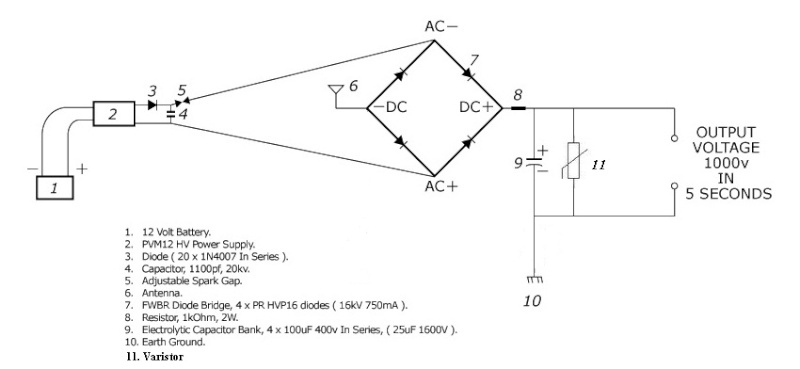
Actually I think it depends on the load applied. And I think the FWBR was an artist mistake. The two diodes before the FWBR doesn't make any sense to me.
And I think the FWBR was an artist mistake. The two diodes before the FWBR doesn't make any sense to me.
Hi guys.
Drak, I am not sure, but thinking simply in plain "surface" the whole thing with these 2 diodes there I think they are put for a scope there: To prevent the FWDBR to change or even destroy resonance. not sure though...
Regards.
<< BP Ultimate + Shell-V Power + Allies (opec) = the Ultimate Power Aligators to Suck People`s Blood !-! >>
It seems to me , as mentioned earlier, that the simplest way to show output power is by heating water. We know how much power it takes to raise the temp of a certain amount of water a certain number of degrees. You wouldn't have to worry about exact voltages or frequencies, right? Just put a heating element on your output and stick it in the water. I'm sure the smarter contributors here could come up with a standard test setup.
Just thinking....
I'm glad you bought this up again, as it was me who mentioned it earlier.
I still think it makes sense, & I'm glad it doesn't just make sense to me (thought I was going mad there for a moment).
Would a normal heating element work at high frequencies?
Or would the output need to be rectified first?
Either way, no one can argue with good old fashioned "school-boy physics" as a proof of concept, can they?
(Unless they're afraid of getting their device wet )
Try this try that, what a load of baloney, you think I haven't done any experiments ?
How dare you tell me to try this and that when you won't even show
something as simple as the non power dissipation you claim will happen
through a simple resistor. Just show it.
I should have taken that out. I guess I got ahead of myself.Should not be in the second one either. Sorry about that. It would not benifit the circuit at all.
I am piecing some information together from various places, in the hope I can help us all reach a conclusion.
Here is JoeFR's Don Smith simplified circuit video. It is based on the non public circuits that Don Smith personally disclosed to Bruce A. Perreault via email before his final surgery.
It is important to know that Don also admitted to Bruce via email that the coils were purposely included as a distraction.
Originally posted by Romero
Someone should try it with these modifications too. The load should not be continuous, discharge the cap using mosfets or spark plug.
One of the most important things I've very recently learned from Romero
is that standing waves are the fastest method of charging capacitors.
This is how Romero's previously posted circuit is able to continue to work. The scope pattern was taken just before the LED rectifier.
All working 'hairpin' circuits that I have ever seen have centre tapped earth grounded NSTs, parallel spark gap with two doorknob caps.
To the best of my knowledge 'hairpin' circuits produce high frequency, high voltage, zero amperage.
Has anyone noticed the wave pattern of a caduceous coil and straight DC line in the middle of the scope.
Although the scope pattern in this Romero's case is low voltage.
I have never seen anyone capture a waveform like this on a 'Hairpin' circuit.
I am guessing because of the voltages involved. 5volt/div
Originally posted by LtBolo
DC is interesting too. Two standing waves in two different coils, 90 degrees displaced and 90 degrees out of phase, produce a traveling wave that would electrostatically push current in a single direction, creating a DC bias. Easily demonstrated in a spreadsheet. Not so easily demonstrated in a circuit.
Ignore the figures in the below schematic.
I wonder if standing waves can be incorporated into these or similar Don Smith circuit variations being discussed / experimented with?
As a final note:
Originally posted by LtBolo
Something missed over and over is the difference between lumped LC resonance vs standing waves. Standing waves are resonant, yes, but are a function of propagation delay. Standing waves and propagation delay add an entire new dimension to the design...phase and time. When we use lumped LC to control standing waves...interesting things happen.
An input of 9500 volts into a voltage divider using an 80ohm and a 1ohm resistor yields 117.284v. What kind of inverter is that? Where can I get one that is tested by the manufacturer?
Maybe its supposed to be 800ohm? That would make the output 11.86v.
Caught me again. Your rightit needs to be 800. You must have the same program I have. I need to go over things better before I post. I just wanted to get something that I thought was an easy way to get off the grid. But I did make those mistakes. Thanks for keeping mr straight your pretty sharp. I didn't notice either mistake until you pointed them out.My bad
I have the same question, is it a 110-110 inverter or 12-110(or 240) inverter.
12v-mains inverters are commonly available things.
My understanding of voltage dividers is the more current you draw from the mid-point the more of a voltage drop you get so maybe the 117v is whats needed to provide 12v output when the inverter is under load?
Also what type/size cap are you using slow-n-easy? Can electrolytics be used here seeing as you have your cap on the output of the rectifier?
[ATTACH]11488[/ATTACH]
It should be a 800 ohm resister without a capacitor.Drak is right. My eyes are bad I can't always see the small print on my computer. But I have tested the circuit and it is sound. You can ask Zilano she originally corrected Don's mistake or not giving out all the info.
That 1st circuit looks like the easiest to start with and I will be starting on that today. -although with a flyback supply as I don't have an NST as of yet.
Please keep us posted on any changes or improvements as you go and I shall do the same .
Regards, Paul
Hey Paul
Before you get started Drak pointed out some mistakes I made in the 3 circuits. It should be an 800 ohm resister
in the voltage divider and there should not be a capacitor in the first 2 diagrams after the rectifier.
Sorry for the mistake. I need glasses I think I can't see the small print in these schems on my computer.
But the circuit is sound. Zilano corrected Don's Misdirection plow before I got the idea. I found that out after I
posted my curcuit. Kind of deflated my ego when I found out that she had already posted a corrected circuit some time ago.
 Tweet
Tweet
 I'm guessing if the
 not sure though...


 Romero


Comment