Announcement

Collapse
No announcement yet.

Donald Smith Devices too good to be true

Collapse
X
 
  • Filter
  • Time
  • Show
Clear All
new posts

  • Wow

    Originally posted by SLOW-N-EASY View Post
    THe WEb site for the frequency of wire is CSGNework.com

    THe program will calsc the length of the wire. Ihave not done extensive test of the charging rate but I am working on it

    I will post more info as I learn and bild my devices. I haven't made one that will get me completely away from the grid

    But I am very close. As far as the diferent builds they all have worked to some degree but I not completely there yet.

    hope that helps in your quest.

    Regards
    Slow-N-Easy

    P.S.The one that I like the best is the Nst running with a Voltage Divider and Inverter from a store it is very simple

    way to get your onw power. Nothing to go wrong and everything has been tested by the manufactures


    Hi Slow N Easy.

    Oh wow--thanx again for that valuable info.

    That 1st circuit looks like the easiest to start with and I will be starting on that today. -although with a flyback supply as I don't have an NST as of yet.

    Please keep us posted on any changes or improvements as you go and I shall do the same .

    Regards, Paul

    Comment


    • I'm not a voltage divider expert but if the output is about 300 watts, will you need resistors rated at 300 watts? If so, then where can you get them?

      Comment


      • free energy Kapanadze replica in Turkey number 2

        hiiiiiiiiiiiiiiiiiiiiiiiiiiii

        free energy Kapanadze replica in Turkey number 2

        free energy Kapanadze replica in Turkey number 2 – Free Energy News


        full regards!

        XILO
        Attached Files
        Last edited by xilo; 06-16-2012, 06:15 PM.

        Comment


        • Originally posted by drak View Post
          I'm not a voltage divider expert but if the output is about 300 watts, will you need resistors rated at 300 watts? If so, then where can you get them?
          The top link is an ebay seller with some large resistors.

          0.1 Ohm 0.1R 100W Watt Power Metal Shell Case Wirewound Resistor items in E-Component From Mary store on eBay!

          Here are a number of manufacturers.

          MF Power Resistor - DDR Power Resistors

          ebg high voltage, high power non inductive thick film resistor for the electronic component industry

          High Power Resistors,Manufacturer of Power Resistors,High Power Resistors Supplier,Power Resistors Manufacturers,India

          Comment


          • Originally posted by drak View Post
            @xee2 and dunfasto

            You are both recommending I alter the circuit to a loud spark gap. I've already done all this. Watch my videos. I'm copying exactly the circuit of this device:


            I don't see how Don could have hid a capacitor on that device unless he hid it in the nst or the PVC pipe.

            Hi drak, this debate has happened already, I agree I don't see how a
            capacitor was hidden. You've done well to replicate the actual device, and
            have shown it does not work. Did you use CW-CCW coils or Both L1 coils
            wound the same way ? Dons were the same way wound.

            The caps across the L1 (primary) are resonance caps not tank caps when
            placed coil side of the spark gap and if placed NST side they would be tank
            caps. Don showed the caps as you have them as resonance caps and had no
            tank caps.

            The important thing to realize about the voltage divider is the amount of
            power dissipated by the resistors. An 80 ohm resistor with 2000 volts applied
            to it will result in 25 amps through the resistor I=V/R current = voltage divided
            by resistance.
            And the resistor will dissipate 50 000 watts P=V^/R, Power = voltage squared
            divided by resistance in ohms.

            So good luck with that anyone who tries it. Even if i could find a 50kW
            resistor I don't think I could lift it not to mention the trouble I would have
            fitting it into the circuit and supplying the power to it. It would be difficult to
            get close to a resistor dissipating 50 kW as well, it would be nice and warm.

            My bar heater (radiant heater) only uses 2 to 3 kW. and it heats my whole room.

            Cheers
            Last edited by Farmhand; 06-16-2012, 08:03 PM.

            Comment


            • Originally posted by Farmhand View Post
              Hi drak, this debate has happened already, I agree I don't see how a
              capacitor was hidden. You've done well to replicate the actual device, and
              have shown it does not work. Did you use CW-CCW coils or Both L1 coils
              wound the same way ? Dons were the same way wound.

              The caps across the L1 (primary) are resonance caps not tank caps when
              placed coil side of the spark gap and if placed NST side they would be tank
              caps. Don showed the caps as you have them as resonance caps and had no
              tank caps.

              The important thing to realize about the voltage divider is the amount of
              power dissipated by the resistors. An 80 ohm resistor with 2000 volts applied
              to it will result in 25 amps through the resistor I=V/R current = voltage divided
              by resistance.
              And the resistor will dissipate 50 000 watts P=V^/R, Power = voltage squared
              divided by resistance in ohms.

              So good luck with that anyone who tries it. Even if i could find a 50kW
              resistor I don't think I could lift it not to mention the trouble I would have
              fitting it into the circuit and supplying the power to it. It would be difficult to
              get close to a resistor dissipating 50 kW as well it would be nice and warm.

              My bar heater (radiant heater) only uses 2 to 3 kW. and it heats my whole room.

              Cheers
              Hi farmhand!

              when voltage is high the amps are low. so higher wattage resistors not needed. if you look at Don smith pics of bigger nst the cap bank uses like 2-3 watt resistors not more. the amperes work in free energy at transformer stage not before that.

              one more thing when resonance happens we have standing wave right? agree? whether its radio resonance, sound resonance or tesla electroststic electrical resonance. we have standing wave. now what is standing wave ?


              it has maximum amplitude upper half and lower half. its total energy is zero means electrostatic amps are zero. when this energy pulsed or passed through a ferrite or metglas turns into energy with amps. if one wants to use this energy directly than one has to use a single diode like we use in radio and use the upper half or lower half of standing wave. to use both halves don used two diodes and charged the caps. which were again pulsed to transformer. pulsing through spark gap lowers the frequency.
              anyways its hard to make one understand free energy.

              lol i was likes you farmhand when i didnt understand the principle of free energy. you will understand it. it will take time.

              now to the question below

              see image below and tell me how many watt resistors you see?


              Full regards

              XILO
              zero voltage input!
              Attached Files
              Last edited by xilo; 06-16-2012, 08:05 PM.

              Comment


              • Originally posted by SLOW-N-EASY View Post
                Hi All

                I just figured out what was wrong with my circuit and how to fix it a couple o days ago. And I was beside myself.

                Only to be surfing the web Last night and find what i discovered allready posted on the net. Brought my ego

                down a step or two. but anyway, Here is what I came up with and if anyone is interested check it out. In 1 of

                the files is a simple way to get off the grid without alot of expense. And depending on what size Inverter

                you buy It will supply most of your house current except maybe air conditioning. I'm not sure about

                that. But the NST I am using puts out 285 Watts and that translates to 12 volts @ about 23 amps. If I am not mistaken.

                I could be wrong but maybe someone that is more educated about that subject could speakup and be more

                specifiec.

                regards


                There are several things wrong with these drawings.

                In the first drawing-
                the resistors would burn up. P= V^/R
                9000x9000= 81000000 / 80 ohms = 1012500 watts.
                Also the bridge rectifier is drawn wrong the input is to the DC output of the
                bridge and the output is from the AC input. The circuit is shorted by the FWBR.
                EDIT: considering the diodes in series with the secondary output leads the
                FWBR is not even necessary, it's just more voltage drop.

                In the second drawing-
                The NPN transitors are drawn oriented the wrong way, the emitters are collecting.
                Same as the first drawing concerning the FWBR and the resistor divider.

                Cheers
                Last edited by Farmhand; 06-16-2012, 08:02 PM.

                Comment


                • @ Xilo

                  I thought these were bleed resistors.

                  @ GSM

                  I have heard on the grapevine that there are other circuits that work in this fashion without this LED bridge, with much higher power. The starter battery is larger too.

                  One of the most important factors to consider is that when the wire lengths are changed by even a couple of millimeters the circuit won't perform.

                  @ Drak

                  My understanding of the capacitor you asked slow n easy about is that is it to slow the frequency down.

                  Comment


                  • Originally posted by xilo View Post
                    Hi farmhand!

                    when voltage is high the amps are low. so higher wattage resistors not needed. if you look at Don smith pics of bigger nst the cap bank uses like 2-3 watt resistors not more. the amperes work in free energy at transformer stage not before that.

                    see image below and tell me how many watt resistors you see?


                    Full regards

                    XILO
                    zero voltage input!
                    You've been drinking the cool aide.


                    If you have 9000 volts in a capacitor the only thing that will restrict the
                    current during discharge is the resistance met by the discharge.

                    There is no use looking at Don's devices they are dodgy.

                    Set up the experiment, keep a capacitor charged to 9000 volts then discharge
                    it through an 80 ohm resistor while trying to keep the capacitor charged to
                    9000 volts and see what happens.

                    Show us this . End of story, if you say it is possible and you state things in
                    opposition to common knowledge then Show IT.

                    If I am wrong I am willing to admit it publicly.

                    This resistor divider thing was discussed right back at the beginning of the thread.

                    Cheers

                    EDIT: Yes those are bleed resistors as soundiceuk mentioned. They are high
                    OHM resistors to slowly drain the HV caps for safety reasons. IF the HV caps
                    were charged to 10 000 volts and a 1 Mohm (1 million-Ohm ) resistor is
                    across the terminals of the capacitor then using Ohms Law there will be a
                    10mA bleed current to discharge the capacitor, then using Joules Law the
                    time it takes to discharge them with that current could be determined.

                    I think. I haven't done the calculation, anyone up for it ? It pays to check
                    each others calculations.

                    Actually that calculation would be a waste of effort considering the depleting
                    voltage of the capacitor and the virtually impossible nature of calculating the
                    time, easier to just time it.


                    ..
                    Last edited by Farmhand; 06-16-2012, 08:24 PM.

                    Comment


                    • Proof of Concept

                      It seems to me , as mentioned earlier, that the simplest way to show output power is by heating water. We know how much power it takes to raise the temp of a certain amount of water a certain number of degrees. You wouldn't have to worry about exact voltages or frequencies, right? Just put a heating element on your output and stick it in the water. I'm sure the smarter contributors here could come up with a standard test setup.
                      Just thinking....

                      Comment


                      • Originally posted by Farmhand View Post
                        You've been drinking the cool aide.


                        If you have 9000 volts in a capacitor the only thing that will restrict the
                        current during discharge is the resistance met by the discharge.

                        There is no use looking at Don's devices they are dodgy.

                        Set up the experiment, keep a capacitor charged to 9000 volts then discharge
                        it through an 80 ohm resistor while trying to keep the capacitor charged to
                        9000 volts and see what happens.

                        Show us this . End of story, if you say it is possible and you state things in
                        opposition to common knowledge then Show IT.

                        If I am wrong I am willing to admit it publicly.

                        This resistor divider thing was discussed right back at the beginning of the thread.

                        Cheers
                        Hi farmhand!

                        you are not wrong farmhand. you havent seen free energy yet. try the woopy circuit or on large scale mr. clean's circuit you will realize excess power.

                        Full regards

                        XILO
                        xero input lifetime output!
                        Last edited by xilo; 06-17-2012, 12:11 AM.

                        Comment


                        • Discharging a 9000 volt cap into an inductor of say 50uh would be a considerable amount of peak amperage. Typically 90% of the voltage is converted to amperage leaving 10% voltage intact. What you end up with is

                          V* ( C / L ) ^.5 or 900 volts * ( 1uf / 50uh )^.5 = 127 amps .

                          The equivalent of a 115 kw nanosecond burst. The resistor in line will evaporate along with body parts if presented the path. Look into exploding wire devices as well as EMP's.

                          I'd have to say that the voltage divider as used in Dons system raises some distinct questions regarding the validity of his device.

                          A much simpler method would be to use an adjustable inductor to control the flow into another cap - a choke - regulated by frequency.

                          Comment


                          • Originally posted by Farmhand View Post
                            Hi drak, this debate has happened already, I agree I don't see how a
                            capacitor was hidden. You've done well to replicate the actual device, and
                            have shown it does not work. Did you use CW-CCW coils or Both L1 coils
                            wound the same way ? Dons were the same way wound.

                            The caps across the L1 (primary) are resonance caps not tank caps when
                            placed coil side of the spark gap and if placed NST side they would be tank
                            caps. Don showed the caps as you have them as resonance caps and had no
                            tank caps.

                            The important thing to realize about the voltage divider is the amount of
                            power dissipated by the resistors. An 80 ohm resistor with 2000 volts applied
                            to it will result in 25 amps through the resistor I=V/R current = voltage divided
                            by resistance.
                            And the resistor will dissipate 50 000 watts P=V^/R, Power = voltage squared
                            divided by resistance in ohms.

                            So good luck with that anyone who tries it. Even if i could find a 50kW
                            resistor I don't think I could lift it not to mention the trouble I would have
                            fitting it into the circuit and supplying the power to it. It would be difficult to
                            get close to a resistor dissipating 50 kW as well, it would be nice and warm.

                            My bar heater (radiant heater) only uses 2 to 3 kW. and it heats my whole room.

                            Cheers
                            They were both the same way.

                            I'm not sure how 50,000 watts would be dissipated on a 20 watt input. I guess if you left it running and charged the cap fully the instant discharge of energy through the resistor would be that high. How are you getting more power out then in? Isn't the energy going to be used right away and not stored?
                            Last edited by drak; 06-16-2012, 08:47 PM.

                            Comment


                            • Originally posted by xilo View Post
                              Hi farmhand!

                              you are not wrong farmhand. you havent seen free energy yet. try the woopy circuit or on large scale mr. cleans circuit you will realize excess power.

                              Full regards

                              XILO
                              xero input lifetime output!
                              Try this try that, what a load of baloney, you think I haven't done any experiments ?

                              Just show the darn resistor with 9000 volts in a capacitor discharging through it.

                              If you don't I can only assume you can't.

                              How dare you tell me to try this and that when you won't even show
                              something as simple as the non power dissipation you claim will happen
                              through a simple resistor. Just show it.

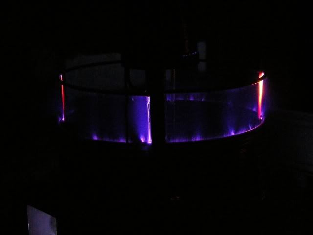
                              Here are some piccies of some of my experiments/observations.

                              What do you see in the picture's, cold electricity, energy outside the wire's ?
                              Do you see the ambient excited ? Do you see resonance ?

                              The energy doesn't want to stay in the wire's.


                              Uploaded with ImageShack.us


                              Uploaded with ImageShack.us


                              Uploaded with ImageShack.us


                              I've done plenty of experiments. But I still keep my mind open to see reason and use common sense.

                              Show us the resistor not dissipating energy.


                              ...

                              Comment


                              • Originally posted by drak View Post
                                They were both the same way.

                                I'm not sure how 50,000 watts would be dissipated on a 20 watt input. I guess if you left it running and charged the cap fully the instant discharge of energy through the resistor would be that high. How are you getting more power out then in? Isn't the energy going to be used right away and not stored?
                                You must let it oscillate without dumping so each period this 50kW of power is sustained. Then it become true 50KW not just impulse...

                                Comment

                                Working...
                                X