-
-
Energy Amps
MikeComment
-
Energy Amps
MikeComment
-
Energy Amps
FREE ENERGY # 35 BI-TOROID TRANSFORMER - 377 % OVER UNITY MOTIONLESS - YouTube
http://www.energeticforum.com/renewa...-platform.html
Power Amplication
MikeComment
-
Energy Amplifiers


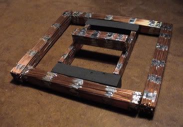
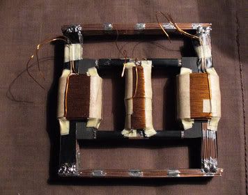
Energy Amp homework fotos
MikeComment
-
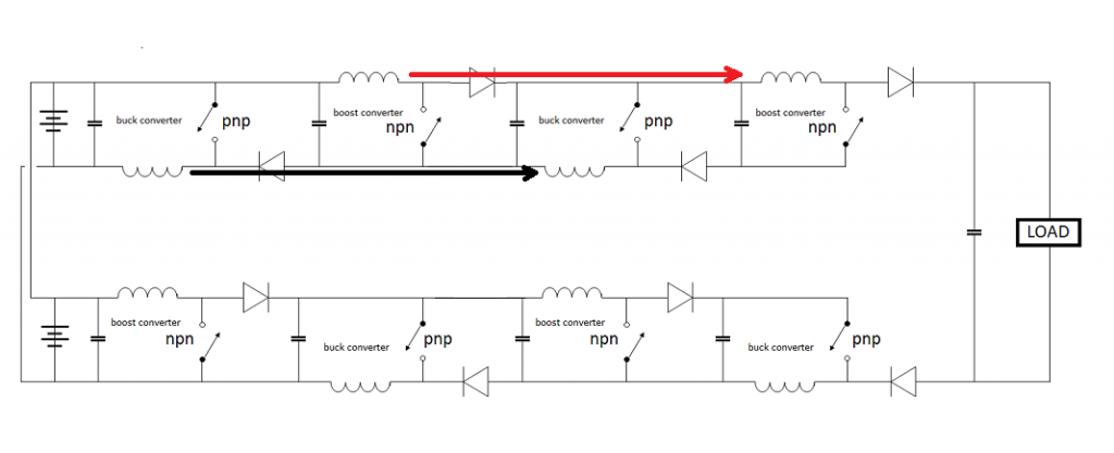
Hey MikeEach switch degrades the amount of power being processed in tiny amounts so the more buck-boost-boost-buck stages add to more and more losses.
This is true there are switching losses but in an overunity situation there should be gain with each stage.
What worries me is the coil to coil reaction, one coil would be getting hit by bemf on the opposite side, this alternate pulse will change the reactions. A coil getting hit with pos pulse will give a neg return this polarity change will load up the caps wrong. I dont really think the added stages will work because of this.
But hey who knows
 Last edited by Dave45; 08-03-2014, 11:40 AM.Half of the Answer is knowing the right Question
Comment
-
Hey Mike
Check out this vid, especially the iron ring, now he has 300kv 6-8 inch's apart and the iron ring stops the arcing.
Somehow the ring will not allow ionization through its center, this barrier should separate pos and neg ions and keep them from recombining.
Thats the problem with ions they recombine especially when the electrodes are in close proximity to each other.
https://www.youtube.com/watch?v=zpkh7_Eyctw
Half of the Answer is knowing the right QuestionComment
-
Rings
Yeah I see the ring Dave45Originally posted by Dave45 View Post
Aside from the sensationalistic potty mouth tactics to gain a worldwide response we could say this guy is putting all of our fears to rest about high Voltage So much for walking around on egg shells worrying if it is going to blow.
I see the ring and knowing about High Voltage, that size electrode should jump across from gap to gap but instead goes all the way out past the large ring first which is miles to travel.
The Bi-toroid has taught use about flux paths and that energy switched and induced into coils can be recirculated. So what we should be learning about coils is that their cores are important first in that depending on frequency of switching the heat generated represent losses.
We all know that part. Laminate cores , ferrite, black sand, whatever til we arrive at the best core material for any given load, uh inductance, wire size, etc so switching frec's are not overloading and driving out of resonance.
We all know that stuff. Put the coils in a nice comfortable operating range with the least amount of stress on the system, this is resonance generally.
However looking at the Bi-Toroid we have no switching frequency with the basic system. We still have an oscillation though.
This oscillation comes in the form of an AC sinewave at a frequency of 60 cycles per second known better by the HZ designation 60HZ.
We all know that. So why not 120hz or 240hz and on up to see what may or may not occur? I agree, but for now we need to examine the Bi-Toroidal core arrangement. This will enable us to create more effective coil driven circuits.
I earlier posts we see coils producing energy when magnets are attached to them because the magnets do the same thing as the Bi-Toroid lesson taught us, recirculate or redirect the FLUX PATH.
If we recall the large ENERGIZERS John Bedini has built we see huge inductors and large weak magnets that not only trigger the transistors but if the system is bigger and the coils create enough ION Energy to surround coils out far enough things change. Also if you notice a network of large rings in the form of copper is used to collect energy. Not just electricity but the other forms of energy.
Otherwise the Bedini Energizer Magnets if only needed for triggering would not need to be any bigger than the bike wheel designs, instead we see JOHN B. using huge beautiful double North Pole magnets costing huge somes of money to arrange, WHY??
Flux path Engineering Boys and Girls.
Then huge expensive magnets are cut with ceramic cutting machines at perfect angles, two of them facing other another to form and produce an altered FLUX PATH.
We all see these rings on the larger Energizers. I wonder if the the combination of redirected energy with the spinning magnets and large copper rings are keeping the ION energy pos and neg from recombining?
Regardless, we need to make sure that we arrange our coils so that the energy can transfer from or through one to the other so recirculation may occur.
Energy pumping circuits are a dime a dozen yet when JOHN BEDINI does it he gets a 10X:1 COP putting 240 watts into the system and gets 2400 watts out.
The Energizer lesson and the Bi-toroidal transformers both redirect the flux path for recirculation from one coil to the next so as to relieve the input.
I see people using this recirculation Bi-Toroid to pulse coils with their switching circuits, also some using magnets as part of the core to redirect flux lines.
Free standing coils that are pulsed need to be put near each other so the exchange for collecting their BEMF energies can take place.
If the rings as are pointed out do keep the ION ENERGY separated then it may be possible to use them by placing other pulsing coils in the circuit for energy extraction and recirculation or some would say MAGNIFICATION because as RE-collections and RE-circulation takes place of the same input energy, multiples will arise.
These are my thoughts on the subject of pulsing coils, magnetic flux paths and recombining recirculated ION energy in an effort to produce an ION TANK or reservoir of ION ENERGY.
Once an ION TANK device is accomplished we will have an endless connection to the energy we seek. ION Energy is all around us but we are not able to keep the ION energy Component values separated as you have pointed out DAVE45 .
.
MikeLast edited by BroMikey; 08-03-2014, 09:32 PM.Comment
-
Rings
Notice the large Ring??? In this case it is said that the ring is a collection device for IONIC transfer.
MikeComment
-
Rings
Here are a few more rings. Don't let anybody sell that wooden nickel where a toroid core such be stayed away from. Toroidals ARE rings and may well serve a similar purpose as the other experiments WITH rings.
Oh yeah back to the picture of the Energizer. Copper pipe it used to carry normal electrons yet the skin effect is a well known so the radiant travels on the skin and not down the center of the solid wire.
ENERGY-RECYCLING TRANSFORMERS

Please remember this: Notation: Please remember.
I have the Bob Boyce hex controller. I have the toroidals WITH the wire. Remember this that radiant travels along the outer skin of the wire so my wire it silver coated.
Silver wire is expensive but has it's place.
Bob has related to me over the phone and in person at my house the complete operation of his invention many many times. I had Johans code at one time for charging batteries I think I have it somewhere but don't understand it..
I know something about why it works.
Resonance is not everything.
In Bob's tech the alternator was failing on his boat and he got huge boosts of energy during races not knowing where from.
His work was to find out why THAT 3 winding motor generator called an alternator could randomly kick out so much more power and Bob came up with a modified sinewave inverter alteration to start then adding 2 more frec's.
42khz,21khz,10.7khz is a generalization.
These 3 were made to conflict with one another intentionally to open the fabric of space. These 3 frec's were set to interact and conflict just as the car alternator did.
All I am saying is resonance is not the whole universe. The field I am referring to is called a torsion field with a cyclonic swirling force. This is where forces are MADE BY FORCE to interrupt one an other nature will come in to repair the beach.
MikeLast edited by BroMikey; 08-05-2014, 01:57 AM.Comment
-
Thinking Back
I don't have much time right now but let me rephrase about systems that amplify energy. Not only diverting the flux path but also conflicting or slightly altered frequency harmonics that ARE in sync or in resonance can cause openings in the Aether.
Let me say it again.
The explanation for a 3 channel primary and one secondary like in one of the Bob B. pulse circuits goes like this. The alternator that failed lead Bob to find the answer. It wasn't pretty picture perfect resonant sync on a scope that was found to bring in the extra from who knows where.
When these circuits are adjusted to cause turbulence a whirling tornado down through the center of the toroidal increases in size and magnitude.
When it is picture perfect resonance on a scope ain't nuttin goin on but da rent. The key question is, what did 3 winding alternator do. And that alternator was on it's way to it's death taking a royal beating.
The failing alternator was anything BUT in perfect resonant harmony (Give me a massive break) so the conclusion is that the replicated wave forms as seen from the failing alternator were in conflict.
Anyone with any common sense whatsoever knows that a car alternator that the diode bank is leaking passing ac and dc causing heat can not be and picture perfect resonant wave.
People all over the web focus of resonant waves thinking that resonance is some how the most important piece of the puzzle.
So are we going to called it resonance when the circuits are adjusted to conflict and draw more power? Are you? Because that is how it is on these systems.
Resonating with what? We want to resonate with the Aether and the Aether is keep everything closed up, sealed up so the Aether is on the outside of our systems. The Aether does not want us resonating with the Aether because this constitutes a break.
The Aether is the MUMU Nature with her arms open wide to surround and keep everything the same. We want to resonate with MUM and MUM sees resonance on the inside as harmony, no conflict.
However if we figure out how to resonate with nature don't forget the consequences of not being able to control the door once it is open you had better know what you are doing.
Johan had a power surge so big that it fried 200 amp power line circuits all the way to the pole. This is an avalanche where an experimenter opens a door to resonate or connect with the Aether.
We are not ready to do that as beginners. Very few can control it where the door is open slightly and can close it.
The only thing that some of these circuits work well with are HHO cells or batteries because uncontrolled reactions with occur. Maybe a water capacitor.
I saw Stan Deyo's talks about coils all over an aluminum craft to lift it.
These are similar in design where the simple 3 channel generator works with water and the 6 channel up to 12 and 16 channel produce enormous amounts of energy for lifting against gravity.
Resonating with MUM Nature is a different set of rules.
MikeLast edited by BroMikey; 08-05-2014, 02:35 AM.Comment
-
Hey Mike I agree we are working with Torsion fields
So I started playing with the joule thief schematic,
The last one is interesting it loads up the cap on both sides then is recycled through the switches, capacitive discharge.
Half of the Answer is knowing the right QuestionComment
-
Circuits
I think we all tried this one right? However with all of the circuit pictures that you can generate with your machine, I dare say that most of them have ever been tried. Did you see that last video of Wesley, in the Kapagen thread where he has an OU transformer using 3 ferrite rods?Originally posted by Dave45 View Post
https://www.youtube.com/watch?v=OhJY...ature=youtu.be
Well I think it is 3 rods? He sounds like he is saying 2 rods but the picture shows 3 rods very small. He is running 4.6 watts and claims an 8 watt output or that he is lighting two 4 watt bulbs.
He is a teacher engineer. Wesley explains proper measuring techniques so as not to confuse input output figures.
Like many he is lighting 2X4 watt lamps off a special tiny transformer and using only 4.6 watts but I am unsure if the bulbs are full bright and so forth.
One very important item he talks about and shows specifically is the winding of the transformer. The direction of winding is changed once the center rod is covered and reverses direction but goes over all 3 wound rads together.
He also points out the reason being that cancellation of self induction takes place for a net magnetic field of zero.
Also that this is an OLD OLD practice when winding wire wound resistors so self induction is cancelled out.
The Kapagen and other winding instructions have similarities including this one where winding can be free to produce energy without being directly coupled to the primary.
I think the goal to finding MORE transformer designs is to make them where flux paths are not arranged in the conventional sense. So this means pulsing a coil then finding away to collect the ION field without direct coupling.
Some use the term "LOOSE COUPLING"
JOHN B and many others have had tiny circuits running for the last 50-100 years and we have not found their secret even with far more at our disposal.
MikeLast edited by BroMikey; 08-05-2014, 08:22 PM.Comment
-
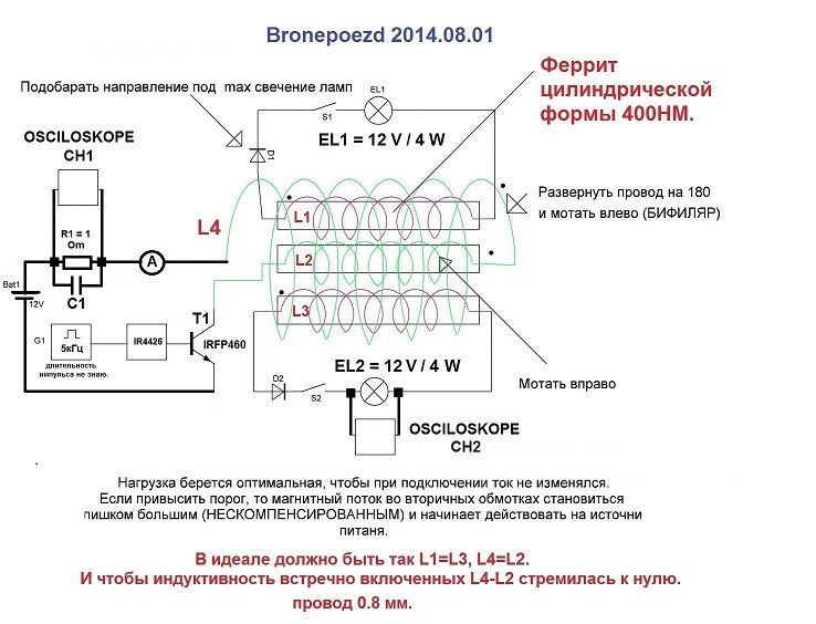
This was posted on OU forum, Im like everyone else dont know if its ou but is an interesting setup.Did you see that last video of Wesley, in the Kapagen thread where he has an OU transformer using 3 ferrite rods?
I need to study the ac reactions in a coil, I got into studying the boost and buck because they were simple.
 Half of the Answer is knowing the right Question
Comment
-
Its interesting I wonder if you could add two more cores with secondary's wound on them, well I know you could but how would it effect the power draw.
He's using an npn trasistor so we can get an idea of whats happening with the coils, notice the orientation of the diodes on the secondary's.
And they make alot of since it push's amperage into the secondary's on the pulse and push's voltage on the collapse.
The primary looks to reverse its winding direction as it comes around the outside, not sure.
It would be interesting to switch the connections and use two primary's in parallel and one secondary.
I wonder if you used three coils in parallel as primary's with different winding ratio's could you hit a secondary with three frequency's or would it just take the path of least resistance.
All three coils would have to be harmonically tuned to a specific frequency.Half of the Answer is knowing the right QuestionComment
 Tweet
Tweet


Comment