Announcement

Collapse
No announcement yet.

Cap Dump Circuit

Collapse
X
 
  • Filter
  • Time
  • Show
Clear All
new posts

  • Originally posted by Dave45 View Post
    Hey Matt you still around.
    Do you mind if I post your circuit on another forum?

    No go ahead, you know who it belongs to. Make sure to post the fact that they should be separate coils wound opposite or some genius will put it all together and it wont work. Post a link.

    Originally posted by BroMikey View Post
    Go for it man it is open source free fun.....
    Mike
    ??????????????????
    Its nice to be asked, thats real manners. I am glad you feel free to speak for me. Maybe you should take a lesson from Dave I might post more.

    Cheers
    Matt

    Comment


    • Hey Im sure you guys are familiar with OU forum
      ENERGY AMPLIFICATION
      Half of the Answer is knowing the right Question

      Comment


      • LOL Closed group HUH? Where did you read that. Your gonna get that mad because I told you Dave was polite? And of course I misread, "It all FUN.."

        Thousands of people HUH? LOL

        Stop your making my stomach hurt your just laughable. LOL

        You might learn something one day if stop trying to know it all. All I wanted to do was help ya. Its your own hard head that stops that. Your failing yourself. Like I told you before I have Walmart chargers that work better than the crap you have put together. You have no clue, and anybody who has taken the time to look can see it.

        Grow up Mikey, clean your house, its filthy. Be humble and listen to people who know more than you. All your doing is burning coal.

        Matt

        Comment


        • Big Cap Dump Ciruit

          Here is the BIG Capacitor discharge unit I recently built.

          It can throw a pulse or 60 amps 100vdc without smoking the traces in 2 days.

          I have some scope shots coming of the ringing and switching.

          After this I will be exploring Matt Jones latest open source "ENERGY AMPLIFIER"

          that was "GIVEN" to him by "JOHN BEDINI" great day

          BroMikey's Science Projects

          Many experimenters think they understand Capacitor Discharges considering them an inefficient means of charging batteries. I have seen some take a PC power supply to battery thinking they had the same thing as this circuit.

          So I guess maybe they build it first.

          Mike

          Comment


          • Scope Shots 4 DUMP

            Originally posted by Farmhand View Post
            yeah you got it, kinda, the coils inductance slows the flow of current from the
            supply to the dump caps, I'm using smoothing caps because I 'm using a
            transformer, I can't setup a large setup like yours but I can set up a smaller version.

            So with the right coil between the supply and the dump caps and the right
            "on" time and "off" time we should be able to get down to almost zero current
            at switch off due to the coil storing the energy and causing the dump cap to
            drop voltage without drawing directly from the supply during the dump time,
            the dump caps fill when the switch is off because the coils "momentum"
            causes it to discharge into the dump caps due to the switch turning off.

            The intention isn't to heat up the coil or anything and a coil with less
            resistance but a with the appropriate inductance is better.

            I'm now using a microwave oven transformer primary, and with 30,000 uF I
            can get the cap to fully discharge in around 70 mS or less which leads to an
            almost no current situation at switch off. it takes about 350 mS to recharge
            the cap and it goes to a slightly higher voltage due to the storage of energy
            in the big coil. The peak current is the same if the voltage is the same and
            the resistance of the current path on discharge is the same. This is a way to
            isolate the supply from the load during the dump without using a second
            switch "except for the diode".

            I'll include some shots of the action of the voltage on the caps in that mode.
            as well as a shot of the applied voltage and resulting current when the
            discharge is short and the capacitor does not get fully discharged.

            The coil and dump cap is a "resonant charging circuit" but it is very low "Q"
            being so low a frequency. I can do from about 1 per second to about three
            per second and keep a voltage rise on the dump caps.

            Also if you put the capacitance and inductance in this calculator it will tell
            you the resonant frequency of the two together which will tell how much
            inductance is required for a given capacitance to get a certain frequency.

            Resonant frequency calculator
            Resonant Frequency Calculator

            The first shot shows the supply capacitor voltage in blue and the dump cap
            voltage in yellow, as the mosfet turns on the dump cap discharges but no
            current flows directly from the supply to the load due to the coil causing a
            delay and storing energy, which is released when the mosfet turns off.

            Second shot shows the applied voltage and resultant current when the
            mosfet is switched on and off before the cap can discharge, this requires a
            fast turn off to do without excessive heating of the switch.
            This shot shows the circuit working at 400 Hz and pulsing the battery with 10 Amp
            rectangles of current for 260 uS, it's 400 Hz 10% duty, That really pumped up the battery.

            Cheers
            Cheers to you Farmhand Man

            Here are some scope shots that I do not really what they are for your review.

            BroMikey's Science Projects

            I am dumping 3 X per second Approx.

            Duty cycle from 10-85 percent depending on resistance input settings and timing.

            Mike

            Comment


            • Learning the Scope

              Hello group Members

              I have great news to tell you. I have made a leap in understanding my scope and how to accurately read rise and fall times. So as I am going through all of the scope settings I see timebase, sweep speeds also sensitivity plus offset.

              This scope requires that you bring the wave into view almost completely before rise can be measured. So now I can do this. What I am seeing is an almost straight up rise when using the 5us scale.

              So as I look at the divisions and also asking the machine to read the rise time I find that they verify each other and this let me know that I have found the proper reading.

              The rise time for dumping 70vdc and down to 20vdc (a little extreme I know) is exactly 1.8us every time with the fall much longer.

              The fall time is in a step formation and then ringing on out to forever and the machine says it is 100us or 50us and if all of the ringing is counted from the coils the fall is as long as 325us.

              Generally when these variables need to be better reviewed scope machines have a 20-80 percent function to give a more reasonable average eliminating noise.
              Of course to me ringing is good noise and is a benefit to shooting a battery but fall time reading are around 50us with the other 150us are comprised of ringing.

              Looking at the scope shots I posted above shows these things i am speaking about.

              So rise is 1.8us, fall is 50us and duration is 350ms to dump the cap bank.

              I am a beginner and am learning fast, reinventing all of the wheels just like you

              Mike (P S) I forgot to tell everyone how battery bank "A" was charged 4 hours faster than it has been charging so this is very exciting news and in the morning I should know more if the voltages read the same or higher but it looks like I have gotten these batteries clean and charging times will be far shorter.
              Last edited by BroMikey; 06-30-2014, 05:30 PM.

              Comment


              • Scope Rise and Fall Times

                For those of you who are wondering if a 555 timer with opto is fast enough to switch a mosfet without heat the answer is yes. Recently I have been re-learning how to operate a scope after 40years of being away from it.

                Well here it is I finally got it up and running to where I know how I got there.

                In the pictures you will see some waves that the machine was asked to measure. The waveforms are adjusted in to view manually with a simple wheel to get close to the part you want to see.

                Then if you have dialed in one wave the computer quickly shows exact figures.

                approx 2us rise and 55us fall.

                BroMikey's Science Projects

                I think? Well I think. I am a beginner and have made a capacitor discharging box for zappin batteries. Nothing to write home about just one experiment after another now for most of my life of 57 years.

                Free Energy is a myth. You will pay big bucks so you better love this stuff or leave it to the dreamers.

                Mike
                Last edited by BroMikey; 06-30-2014, 05:31 PM.

                Comment


                • Attention Cap Dumpers

                  BroMikey here with another great update for your pleasure
                  As many of you know I have been trying for many months now to build an industrial grade capacitor discharging "BOX". It looked easy enough when I built 2 or three small 15,000- 60,000-120,000uf 70vdc capable units so I thought I would build a large one.

                  The biggest one I had made up to that point was about the size of a football complete with timing circuit, rectifier and caps. So what should I do? How could I make one larger?

                  This big box is 12"X12"x30"tall.

                  Well my batteries were piling up and I was running out of time to charge all of these 12vdc batteries individually so i started putting 2 in series for 24vdc and this got me done charging much quicker as I could do two at a time.

                  At the time I was use to running the SSSG oscillator (SSSG=Solid State SG) at 24vdc as an input to feed cold electricity to my rectifier and caps.

                  I was running 65,000uf 100vdc caps at that time and was charging a 12vdc battery up to 16.2vdc. These batteries were not true deep cycles. Later my room filled up with around 1000ah collectively of batteries who ah ratings varied from 12ah-28ah-35ah-55ah-115ah and these were deep cycles. All of these batteries had to be charged now that I had them and were converted to ALUM.

                  Well the best I could do with a dump delivering 10 amp pulses at as high as 35-40vdc was to charge a 100ah battery per day or longer. One day I decided to put two in series and run the voltage up on the dump to 70vdc, it took about the same time to charge two batteries as it did to charge one.


                  So I embarked on a new quest for designing a bigger discharge unit out of necessity. I saw John Bedini build some and found that John used an 80vdc cap to zap 12vdc batteries with. He charged his caps up to 31vdc.

                  Well that was all I needed, a man who could actually show an experiment in plain site got me moving fast. So using this principle I wanted to charge 3 batteries in series and this required high voltage.

                  I used the K.I.S.S. formula so if John Bedini needed 80vdc for a cap then all I had to do is multiple by 3. Bingo 240vdc caps right on the money, right? No way Caps didn't come in that voltage so i went looking for what was available.

                  I found caps were 25vdc,50vdc,75-80vdc,100vdc,200vdc,220vdc,250vdc and on up higher and higher they went but I stopped at 250vdc because this was all I needed to maintain the pattern set forth by a man who had done every free energy experiment I had ever seen.

                  I mean John Bedini has done them all or close to it plus he was never ill mannered or acted like he was the only man alive who had a brain. He treated people fair and I look for that before I follow any experimenter.

                  That's just me, I am careful who I pick to follow. I look at many things. So John bedini really struck a node with me because he is about my age and could teach how to do these experiments with great easy.

                  Anyway 80vdc times 3=240vdc and I ended up with 250vdc.

                  So now these parts were more expensive like 10-15$ EACH AND i KEPT WATCHING THE DEALS of Ebay to I got around 100,000uf of this type of cap.

                  Then all I would need is few fets and I would be pulsing all those batteries in series-parallel at 100vdc, right? Wrong!!!!!

                  First time I hooked up 1-2-3 fets dumping at 100vdc popped the fets regardless of base resistances or whatever because IRFP250 fets could not take the pounding. These fets are fine at 60-70vdc.

                  Then I tried a 500vdc fet and one or two of these exploded in minutes.

                  Then i went to 6 fets and they lasted a week and at this point I started running the calc's. Black Chisel pointed out the pulsed joule ratings for fets.

                  I didn't see that before, that pulsing had limitations measured in mJ and not just amp ratings. I didn't really know for sure though I ran the numbers. All I knew is 6 fets was not enough and things didn't add up. Everyone was saying 2-4 fets and you should be good and I was up to 6 fets and they failed.

                  So I did an experiment. I took my old cap dump and compared it with the new one and this way I could ball park based on the old dump devices that never failed. Well, the old dump used 5 deflection transistors rated at 150watts each.

                  However i had forgotten that the first dump had never used grid power only the SG Osc and now I was fighting to keep high inrush off the my backside of the cap charge up rates.

                  I can't wait to use the ENERGY AMPLIFIER thanks to the man who let the cat out!!

                  The meter was to small for the new dump, I had both banks charged to the same voltage.

                  The new dump pegged the meter while the other dump gave me a 10amp pulse.

                  So I changed out amp meters and tried again using a 20amp meter. This time the new dump pegged the needle again and the other dump showed a lesser than 10amp pulse maybe 4-6amps each time. So today for the same voltage and same uF cap rating I am sending (AS WE SPEAK) a 35amp pulse to a 12vdc battery.

                  This is how I began to go up in size to charge larger and larger battery sets. Charging batteries with an SG or a switch or a solar panel or say genmode will always leave your batteries in need of an extra shot in the arm to maintain battery health and this is why a cap dump is a valuable tool.

                  In the beginning I tried and tried to charge these big batteries with the first dump and the batteries stayed at 13.5 vdc for days and all i was doing was charging, never getting to use any of the power because I needed to reach 15+ vdc first.

                  Well It wasn't happening. I used Genmode operating at 100watts and nothing was changing, the batteries were just to big and to dirty to clean up with such a small pulse.

                  NOW AS OF TONIGHT THE FIRST BIG BATTERY I HAD INITIALLY CHARGED WITH PULSES (AND SMOKIN FETS GALORE) IS GOING UP FASTER BEING MORE CONDITIONED TO RECIEVE THE ENERGY IN THIS FORM.

                  This first battery is charged 4 hours early, unlike the other identical battery that has not had as much conditioning "YET"!! The less conditioned battery is being drained the same every night as the other Huge battery. Both end and start at the same identical figures every night now for weeks.

                  I do the same thing every night and charge at the same power levels everytime.

                  Nothing is being changed "YET" the more conditioned battery is getting done sooner....

                  I am using 12 fets and 4 coils on the collector and emitter to stablize and balance high inrush flows of many thousands of watts of pulse power.

                  The next phase will be to charge my caps without the use of grid power.

                  Wind turbines and solar are what I had thought and then the transition from solar panel to first battery and on to inverter for charging caps.

                  This will be another thread.

                  For now many thanks to the good hearted folks who cheered me up and gave me advice to help.

                  Also I want to say Matthew Jones ENERGY AMPLIFIER post made my heart rejoice because I knew then beyond a doubt that what he posted was a winner for getting the extra I had been looking for in the SSSG.

                  Mike
                  Last edited by BroMikey; 07-01-2014, 06:20 AM.

                  Comment


                  • Here you go.

                    http://www.free-energy.ws/pdf/bedini6677730.pdf

                    ..

                    Comment


                    • Thanks

                      Originally posted by Farmhand View Post
                      Thanks Farmhand

                      I had that one for years. Anything you wanted to point out? I am all ears.

                      I guess you are saying that this is a better way to go?

                      Have you done this one?

                      Mike

                      Comment


                      • You sure are quite Mike
                        Half of the Answer is knowing the right Question

                        Comment


                        • Im in the process of moving my shop
                          got my bench built, Im going to be moving my power supply's and meters today, finally.
                          My next project

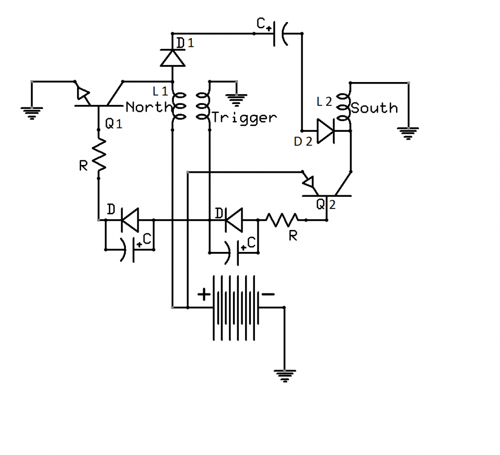
                          Matts bipolar cap charger, Iv been studying it for a long time, Matt put the icing on the cake when he posted the schematic.
                          I have some idea's to enhance the circuit--------split the aether.
                          Get ready for free energy my friend.
                          Half of the Answer is knowing the right Question

                          Comment


                          • Im in the process of moving my shop
                            got my bench built, Im going to be moving my power supply's and meters today, finally.
                            My next project

                            Matts bipolar cap charger, Iv been studying it for a long time, Matt put the icing on the cake when he posted the schematic.
                            I have some idea's to enhance the circuit--------split the aether.
                            Get ready for free energy my friend.
                            Half of the Answer is knowing the right Question

                            Comment


                            • Timing Controls

                              Here is an extra circuit I built last night, Well I am making two like this side by side to control timing and duty cycle.

                              In the picture is the timing section. This lets me do away with the endless variable condition that exists with pots. Pots leave you wondering if you have it back in the same position as adjustments need to be made to lower input power at the end of the cycle of charge.

                              This way the many switches allow for a fixed value. The next step might be to have resistors switched in and out using Zener's. At a set voltage (say 14.5vdc) the input could be slightly lowered and at the very end of the charge lowered again at 15vdc for an hour or so.

                              Timing Control.JPG

                              Mike

                              Comment


                              • Boxing up circuit

                                Now that I am putting everything into one box I have removed the external power supply that is regulated and not connect to the emitter using the same 24vdc pack I am charging.

                                It looks like I am going to use the 30-100vdc as a source and build a tiny buck converter to supply the timing controls.

                                I tried using one of the 12vdc charger batteries but still get cap bank voltages.

                                I tried a 300-500 ohm resistor of high wattage but that is the wrong way to feed my 0-36vdc regulator. isolation is very important and since I have never faced these challenges before they are a hurdle.

                                It looks like I need a buck circuit to produce 20vdc to feed my triggering.

                                I can't get it boxed up until I can power the timing controls.

                                Mike

                                Comment

                                Working...
                                X