 Tweet
Tweet
My Set Up...
Hello to all,
Below is a Diagram of my set up:
[IMG]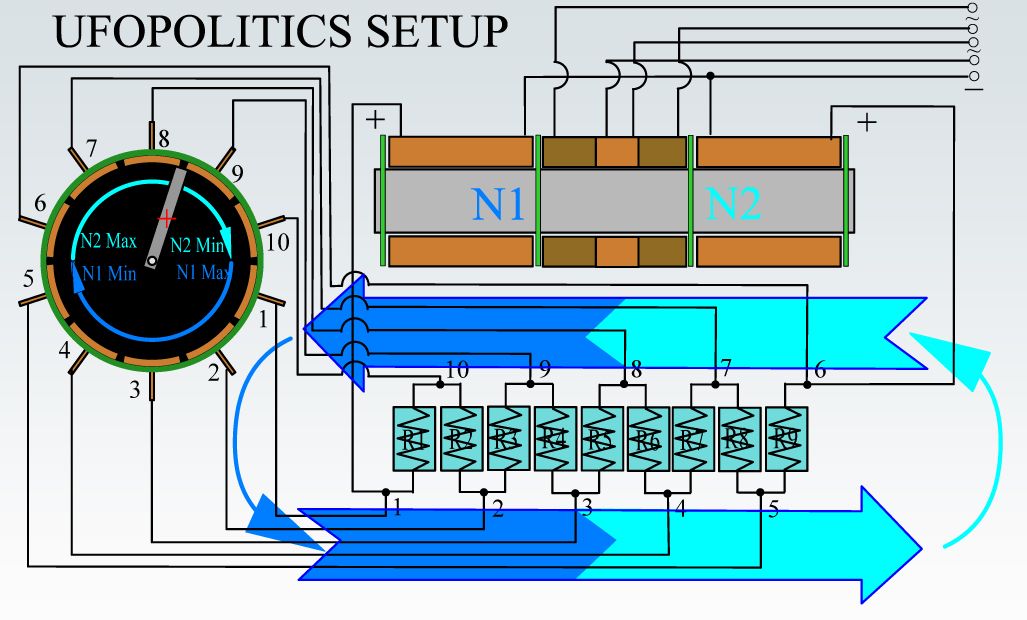 [/IMG]
My Rotary Switch have a 20 elements commutator installed and wired, so, I am not really going to change that because of the work it involves...so, what I would do is just "bridge" each two wires in order to have a ten (10) element comm.
Also, I already have all wires (20) connected to elements and run through rear plate holes...not changing that either, except becoming just ten wires after bridging them, so I am wiring it according to diagram above...
It is not that am lazy, but I am in the middle of completion of two Machines that work on similar principles...so, am saving tons of time by doing it this way...
However, of all Machines this Figuera's Device is the simplest to put together in order to prove Concept. And that is exactly what am after.
I will film a video about it...it is about the fourth video I am making and still not uploaded any as of now (basically Theories and tests about Magnetism)... ...am swamped. But I will "make" time for this, since its simplicity of Coils-Cores.
I will make all Coils movable (in order to test repulse versus attract on primaries, plus adjust the proper gaps) along a 2 inch thick and 5 1/2 inches long solid iron rod...where I will mount them all.
I will use 47 Ohms resistors that I have in stock like 20...from previous tests...and I have got plenty of wire...
I will give it a try to install FIRST an "Exciting Secondary" (not the final Output one) shown at very center of diagram, at center of Main Output Secondary...like I told MM above...I will test this possibility as it works on a typical gen head.
Next week I will be on this full time.
Regards
Ufopolitics
Hello to all,
Below is a Diagram of my set up:
[IMG]
 [/IMG]
My Rotary Switch have a 20 elements commutator installed and wired, so, I am not really going to change that because of the work it involves...so, what I would do is just "bridge" each two wires in order to have a ten (10) element comm.
Also, I already have all wires (20) connected to elements and run through rear plate holes...not changing that either, except becoming just ten wires after bridging them, so I am wiring it according to diagram above...
It is not that am lazy, but I am in the middle of completion of two Machines that work on similar principles...so, am saving tons of time by doing it this way...
However, of all Machines this Figuera's Device is the simplest to put together in order to prove Concept. And that is exactly what am after.
I will film a video about it...it is about the fourth video I am making and still not uploaded any as of now (basically Theories and tests about Magnetism)...
...am swamped. But I will "make" time for this, since its simplicity of Coils-Cores.I will make all Coils movable (in order to test repulse versus attract on primaries, plus adjust the proper gaps) along a 2 inch thick and 5 1/2 inches long solid iron rod...where I will mount them all.
I will use 47 Ohms resistors that I have in stock like 20...from previous tests...and I have got plenty of wire...
I will give it a try to install FIRST an "Exciting Secondary" (not the final Output one) shown at very center of diagram, at center of Main Output Secondary...like I told MM above...I will test this possibility as it works on a typical gen head.
Next week I will be on this full time.
Regards
Ufopolitics


Comment