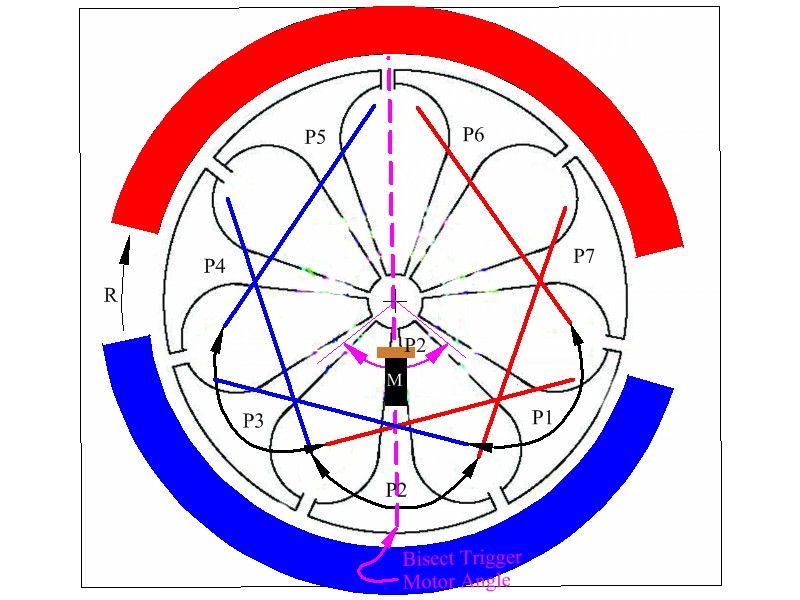
Announcement

Collapse
No announcement yet.

My Asymmetric Electrodynamic Machines

Collapse
X
 
  • Filter
  • Time
  • Show
Clear All
new posts

  • Seven Pole Motor

    UFO,
    The original motor(seven pole) is wound with each coil around three poles.
    Starting from the same point, between two poles. It also looks like it has
    awg 28 or so on it as well. I just had a bunch of #32, so I wanted to use it.
    I may try one more time, to see, they dont take long to wind.
    Mark

    Comment


    • Seven Pole Better View

      Originally posted by pmazz850 View Post
      UfO,
      In regards to the seven pole diagram you posted. Are the coil pairs jumping 2 poles? It looks like the way the coil pairs are numbered, that they originate from the center of the pole. Just want to be sure. I got my hands on two small seven pole motors I want to convert to replace my three pole that I broke the commutator on. They seem like well built motors. Ball bearing, screwed together and brush assy. slips right out.

      Still have to re drill my stator core for the delrin motor so I can wind it up. Been very busy lately and not much free time. I also have to order some mosfets for my pulse circuit.

      Just wanted to check with you on the seven pole wind. Also, how about the comm hook ups and the brush placement?

      Regards,


      Pmazz.

      Hello Pmazz,

      Here is a better view, I just rendered the Pairs at closer interaction with Input Brushes. I show Comm Element for P2, just for reference.

      Now, the adjustment in order to gain Torque-Speed, should be done getting M Brush closer to P1, but not passing P1 Bisector.

      [IMG][/IMG]


      Hope this helped


      Regards


      Ufopolitics
      Last edited by Ufopolitics; 08-14-2012, 10:55 PM.
      Principles for the Development of a Complete Mind: Study the science of art. Study the art of science. Develop your senses- especially learn how to see. Realize that everything connects to everything else.― Leonardo da Vinci

      Comment


      • Hello Turion

        Originally posted by Turion
        Holy crap!!

        I tested the torque on this modified motor, It is indeed scary, running off 24 volts. I am waiting to get a "standard" motor in the mail to test it, since I have cannibalized all THREE of mine for parts. I have to say I did not expect to be able to torque down on this thing like I did and have it keep running. I was smoking the belt, and I will probably have to go to a leather one if it keeps this up. I am quite anxious to run this test on the standard motor. As you can see, I never got close to stalling the motor. Torque Test. Modified Motor - YouTube

        Dave


        Ok Dave,

        The best way to create your Dyno is to design a Lever that sets tension at belt and pulls up Scale by a simple/short movement, the lever make it off a hollow tubing and get inside a long bolt as to the end of lever set a knob that turns that bolt...the bolt will lock by a simple twist into the lever rotating shaft, while getting tension, leaving it in position...

        I know you have to build like a frame cage to enclose all this...as lever should be attached to a ring that rotates within a shaft to lock in...
        However, this way you do not waste time turning scale while motor keeps rotating...plus you also need to take SIMULTANEOUS measurements of RPM's Voltage and Amps increase-decrease, while you are doing this...better to film everything within your Cam view, to write down later and calculate the results.

        Now, with the original Motor you can NOT do this hard braking at high speeds...for sure it will smoke...since ALL Coils are getting energized and no idle-cool off stage is there for them...so take it easy with it...slowly till you take it to almost a stop...don't push your luck too much with it....or will be a "Well Done Crispy" nice Machine...


        Great test, but needs all other parameters to complete.


        Regards


        Ufopolitics
        Principles for the Development of a Complete Mind: Study the science of art. Study the art of science. Develop your senses- especially learn how to see. Realize that everything connects to everything else.― Leonardo da Vinci

        Comment


        • Electronic Goldmine motors

          Not being a motor guy I thought I'd ask if anyone can see a 'good' candidate for a bit of UFO motor mayhem in the motors section at Electronic Goldmine. I have other things to order there and would add a few 'extras' if warranted. Thanks.

          Motors-The Electronic Goldmine

          tak

          Comment


          • Hi Tak

            Originally posted by tak22 View Post
            Not being a motor guy I thought I'd ask if anyone can see a 'good' candidate for a bit of UFO motor mayhem in the motors section at Electronic Goldmine. I have other things to order there and would add a few 'extras' if warranted. Thanks.

            Motors-The Electronic Goldmine

            tak


            Grab a couple of these, 5 pole 2 stator nice commutator.
            Like the radio shack motors big brother and cheaper(+_+)


            Massive 12VDC Motor-The Electronic Goldmine

            Mike Klimesh
            Live to experiment, Experiment to live (+_+)

            Comment


            • Digital Scales...Dyno Spec's

              Originally posted by Turion
              UFO,
              I couldn't get ahold of two digital scales to do the testing the way it SHOULD have been done. I have been to three different stores trying to find a second digital scale and nobody had one. And nobody had a dial scale either. This morning I did find two dial scales that are NOT digital, so I bought them both, and will be setting up that test properly and filming it. That will be a little later today. First I want to run a couple "unauthorized" tests. Amsending you a PM about that.

              Dave
              Hello Dave,

              Ok, for scales I got two mechanical ones, is ok...

              But there are other things you need to make...

              1-You need to attach the Machine Shaft to a Wheel (Peter says of "Known Circumference"), but He uses a One Foot Circumference, just because it is much better when transferring RPM (Revolution Per Minute) to Revolution (Foot) Per Second, therefore I recommend to be of exactly One Foot Circumference.
              2-You need a leather strap, no Rubber Automotive Belts, they do not slip like leather, and tends to "brake", get stock...not good.
              3-You need to measure simultaneously the RPM's at the exact moment you are measuring Pounds or Grams, whatever your scale measures...As ALSO you need to have connected a Volt-meter and an Amp-meter at all times during Dynamo-meter Testing.
              And record everything from an angle that allows reading of all parameters...

              Maybe you will need your wife to aim Tachometer while you set stress on Shaft...(I trust more your wife than you...LOL)...just kidding!


              I will love to also watch what will the Output be , as Amps and Volts, at those moments...

              I will help you do all calculations once you get all the numbers together...


              Regards


              Ufopolitics
              Principles for the Development of a Complete Mind: Study the science of art. Study the art of science. Develop your senses- especially learn how to see. Realize that everything connects to everything else.― Leonardo da Vinci

              Comment


              • Originally posted by Turion
                I have been busy making a wheel with a 1 foot diameter out of plastic, as well as cutting up an old belt for my leather strap, so I will have all the required pieces for testing. Would have had it done, but got a little sidetracked. Will get it done though, I promise. I built a mechanism that will enable me to record all the data at the same time. not a problem. And I will just record it and pull the readings off the video.

                Dave
                Hey Dave, forgive me for putting my 2 cents in here but do you need to make a wheel with a 1 foot diameter or a 1 foot circumference. There would be a big difference. Remember there may be some heat generated from friction. Are you concerned about using plastic?
                J

                Comment


                • One Foot

                  Hi DadHav,
                  Good catch on that wheel size.
                  Dana
                  "Today's scientist have substituted mathematics for experiments and they wander off through equation after equation and eventually build a structure which has no relation to reality."
                  Nikola Tesla

                  Comment


                  • Originally posted by prochiro View Post
                    Hi DadHav,
                    Good catch on that wheel size.
                    Dana
                    Hello Dana, I'm glad things are settling down. UFO will get to it but I just thought if Dave was already starting he might want a heads up in case UFO is busy with something and a few hours behind on the posts.
                    Take care.
                    J

                    Comment


                    • Originally posted by Ufopolitics View Post
                      Hello Vince,

                      Normally a Five Pole Symmetric Machine, each coil comprehends two poles...is that right in your motors?

                      The reason to "Match-Balance" Coils, is in order to set both machines (Original and Mod) in a standard and common grounds to be tested evenly...However, this windings to match Original not necessarily means that is the way to wind Asymmetrical Machines in order to perform better, but, only for purposes of testing related to Amps-Volts Draw and RPM development. I wanted to make that clear to you before proceeding here.

                      Now if Original Coils wrap around two poles, then Modified will do also, except that it will have Double the amount of Coils. Your original comes with exactly Five(5)Coils...and the Mod will have Ten(10) Coils or Five Pairs...However, the Mod will energize just One Pair per "Momentum", while Original will energize the whole Five Coils within same "Momentum"...That is why Original will show less Amp draw (more resistance in total, Ohm Law I=V/R, the bigger "R" the lower "I") when idling (no load), besides forced C EMF by Symmetry, will also create a Counter Resistance that will reduce heavy electron positive flow...reflecting in even less amperage draw. I am saying this because we will never get a very low amp draw on Asymmetry...besides by rotation we get back flow at input if no load is applied to Asymmetrical Machine. The advantages are when Machines are at load...then the opposite happens...and Motors are designed to work...not to stay at idle all times...

                      Now if you set a diagram to Original Input related to its armature coils...Input brushes divide the whole series array in two all times, meaning Resistance Total will be Parallel Formula of Half and Half ...meaning, You said Half way (half coils of total armature) resistance is 3.4 Ohms, so adding and divided by two, we will have same value of 3.4 Ohms

                      So a close "match" will be...One Pair of Coils in the Modified to have around 3.4 Ohms...
                      Now, normally for an Asymmetric Machine that will be a bit high R per Pair, as I recommend to be above or equal to One Ohm per Pair...(1.0 to 1.8, 2.0)

                      Try winding them with 30 awg...finer wire to get a bit more room and gain resistance with lesser turns...


                      Regards


                      Ufopolitics
                      Hi UFO,

                      I finished my build tonight. It ran for a few seconds and then died in a puff of white death.

                      I think the build was fine but it could be the winding. I used 30 awg wire with 21 turns per half pair (eg P1-P3). Each coil resistance was 2.5 ohms when measured from one commutator side to the other (P1M-P1G). I made a short video of how I wound the coils. I'd be grateful if you could take a peek and let me know if there was an error in winding. Asymmetric DC Motor - Winding Question - YouTube

                      Any help is greatly appreciated.

                      Cheers,
                      Vince

                      Comment


                      • Wound Video is awesome...

                        Originally posted by Vincevl View Post
                        Hi UFO,

                        I finished my build tonight. It ran for a few seconds and then died in a puff of white death.

                        I think the build was fine but it could be the winding. I used 30 awg wire with 21 turns per half pair (eg P1-P3). Each coil resistance was 2.5 ohms when measured from one commutator side to the other (P1M-P1G). I made a short video of how I wound the coils. I'd be grateful if you could take a peek and let me know if there was an error in winding. Asymmetric DC Motor - Winding Question - YouTube

                        Any help is greatly appreciated.

                        Cheers,
                        Vince

                        Hey Vince!!

                        Great work on the Modified!...Now your winding video is awesome, yes, that is exactly the way to go...So I was reviewing your short post...Resistance is Ok, 30 awg is ok...Until I read...

                        Each coil resistance was 2.5 ohms when measured from one commutator side to the other (P1M-P1G).
                        Is that Red Quoted (P1M-P1G)...a mistake in your writing here...or you did measure resistance from P1M to P1G?...Meaning you joined Coil Pairs terminals at commutator elements 180 degrees apart?

                        Please let me know...

                        Now, the other thing I have noticed according to your video...you still have a Plastic Brush Cap on the Modified Core...was that the way you had it when you ran it?...because it is wrong...Brushes are supposed to be rotated 90 degrees...I notice the contact terminals are not rotated but as they come from factory...

                        Watch my diagram again...below, note brushes related to stators...and tell me...


                        [IMG][/IMG]


                        Thanks


                        Ufopolitics
                        Last edited by Ufopolitics; 08-15-2012, 07:12 AM.
                        Principles for the Development of a Complete Mind: Study the science of art. Study the art of science. Develop your senses- especially learn how to see. Realize that everything connects to everything else.― Leonardo da Vinci

                        Comment


                        • what type of motors to work with

                          Hello all,

                          to all here doing the right thing!

                          I'm in part of the world where selection is not great.

                          I would like to work with some power, maybe 1hp or better.
                          looking at P Kelly's book the 3 pole might be good.

                          looking at playing with some DC motors. Rewinding for powerful results.

                          When it comes to purchasing them I need to know more specifics,
                          they have
                          3 phase
                          shaded pole
                          brushless
                          perm mag
                          what rpm,
                          what voltage?
                          and more.

                          all questions I will need to answer,

                          please point me in the proper direction.

                          Thanks in advance,

                          Comment


                          • Hi Ufo and Vincevl,

                            Correct me when I am wrong, but at 3min07 on the video, Vincevl isn't directly going from P1 to P4, but crosses over (from P3) the rotor.
                            I thought Ufo this wasn't the wright way.

                            Originally posted by Ufopolitics View Post
                            Hey Vince!!

                            Asymmetric DC Motor - Winding Question - YouTube

                            Great work on the Modified!...Now your winding video is awesome, yes, that is exactly the way to go...So I was reviewing your short post...Resistance is Ok, 30 awg is ok...Until I read...


                            <Stuff deleted>

                            Ufopolitics

                            Regards, Bert
                            Last edited by bbem; 08-15-2012, 01:39 PM.

                            Comment


                            • Clarification

                              UFO et al,

                              I hope to start modifying a motor soon. I may start on the larger motor which has twice as many elements on the comm as poles on the rotor (I hope I got the terminology correct there). I also noticed that the trigger angle shown on one of the drawings crossed the perm. magnets (or N and S fields) at a place that didn't include all of the magnet (or field), but bisected them.

                              So I have two questions.

                              1) If I take the 20 poles and divide them into 5 sections (4 poles each) to wind around, can I attach the wire to a set of elements that are 90 degrees around the side so that the brush housing can remain basically where it is normally and still relate to the windings correctly? This way I would only have to adjust the second set of brushes to align with the first which would need no modifying at all.

                              2) If I wind as described above (having 8 elements for each coil set), can I use only 7 of them as contacts, leaving one unused in order to increase the separation between the firing of the separate coil sets? Could I possibly even leave two as separators? Each element is 9 degrees of rotation (360/40 = 9).

                              Whatcha think?

                              Bob

                              Comment


                              • He is Ok Bert...

                                Originally posted by bbem View Post
                                Hi Ufo and Vincevl,

                                Correct me when I am wrong, but at 3min07 on the video, Vincevl isn't directly going from P1 to P4, but crosses over (from P3) the rotor.
                                I thought Ufo this wasn't the wright way.


                                Regards, Bert

                                Hello Bert,

                                Vince is Ok Bert, He is following the same direction of first wind...into second coil...that is what I look at...you could make the "crossing under or above...as long as it keeps same direction, just like winding a straight coil.
                                When this tends to a lot of confusion, is where the two coils are right next to each others...like it was the case of Turion with 16 Poles...that you practically have to make a full "U" Turn...then it reverses to Coil1.

                                Normally a mistake like setting all Coils Norths or Souths where N-S coils go...the Motor will never turn.

                                Regards


                                Ufopolitics
                                Principles for the Development of a Complete Mind: Study the science of art. Study the art of science. Develop your senses- especially learn how to see. Realize that everything connects to everything else.― Leonardo da Vinci

                                Comment

                                Working...
                                X