Announcement

Collapse
No announcement yet.

My Asymmetric Electrodynamic Machines

Collapse
X
 
  • Filter
  • Time
  • Show
Clear All
new posts

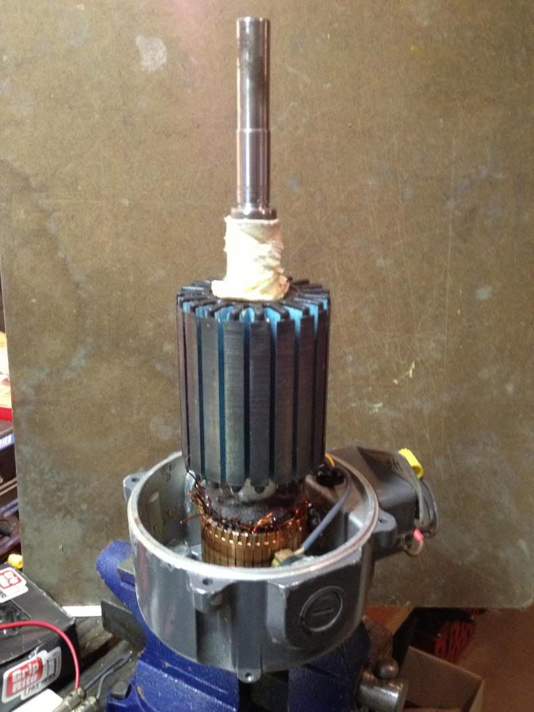
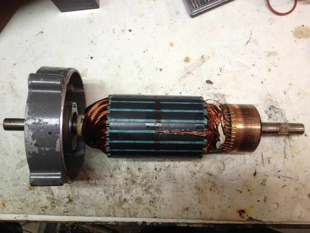
  • Grind out stamped in commutator wires

    Originally posted by Ufopolitics View Post
    Hey Sampojo!!

    My Friend...I can not believe such a great Asymmetric Motor Builder like you... are stock over a couple of tiny, weak wires...

    How good are You with a Carbide small wheel...and a nice High Speed Dremel, with a Super Duper Universal Motor within?...

    Move wheel not only cutting deep into gap, but also like sideways, ONCE INSIDE GAP...grinding wire material out...please, use Goggles and a Dust Mask!

    Grind,cut up all those wires and at same time clean up the Commutator Gaps...if, in any event they go a bit wider because of disc cuts...just use a bigger gauge wire...and attach it to Coil wire...or use it like I did on Imperial, as "Top Rivets"..they never got loose ever...even at 9000 RPM's Plus...

    After you are done need to "Resurface" that Commutator where the new wires would go...no lathe?...then file them up! (JUST at the wires and gaps, NOT where brushes ride!)

    That would do my friend.

    Kind regards

    Ufopolitics
    So I guess you scorn at the screwy idea Me "stock"? HAH I am going almost as fast as a snails pace!!!

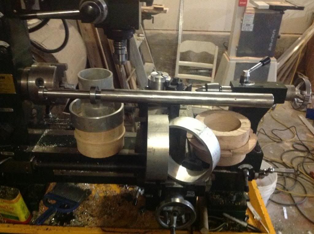
    I remember you mentioning this briefly, but I took a look at my diamond blade and thought it couldn't do the job, too narrow. Maybe some grinding blade available that is a little wider...

    Or just more work than I would like, yuk. I also was under the impression that the bottom of the channel was supposed to be copper and when I got done with that, it would no longer be, thus messing it up... Apparently not so. I know I wouldn't have a square bottom, seemed a drawback. Great to hear that this treatment will not destroy the commutator. I guess I bought $10 worth of screws for nuttin'.
    Last edited by sampojo; 09-23-2013, 05:18 AM.
    Up, Up and Away

    Comment


    • Originally posted by Ufopolitics View Post
      Hello John_G!, long time!

      It is great to know you are making such nice tests...and yes...that is a very interesting spark...

      What is also very interesting...is if you touch that wire lead to any motor ground or its outer body...it will also spark. even though there is absolutely no connection between body ground and either input or output terminals...

      Thanks for sharing this video!


      Warm Regards


      Ufopolitics
      Hi UFOpolitics

      I couldn't get the HV on the casing, however I did find that on pulsing below the amount needed to turn the motor, I was getting a shocking current, this from a 12v input.

      Short video at:

      ufo res1 1 - YouTube

      Regards

      John

      Comment


      • Hello Sam

        The blade I use is a Dremel 1.5 inch EZ-Lock grinding blade. It has the word GRINDING and METAL on the front and is just the right width for your wire. It does not wear down fast giving you plenty of time to get her done. I use it on steel also. Cuts those printer roller shafts of hardened stainless steel too.
        Dana
        Dana
        Last edited by prochiro; 09-23-2013, 11:05 AM. Reason: spelling
        "Today's scientist have substituted mathematics for experiments and they wander off through equation after equation and eventually build a structure which has no relation to reality."
        Nikola Tesla

        Comment


        • Introducing ACS712 Low Current Sensor from SparkFun and its Config using Arduino

          Originally posted by Ufopolitics View Post
          Hello Light!


          Great work my friend!, excellent running videos and whole set up!.

          When you run next tests on this Set up, see if possible to measure Amps at start and Amps after is running...
          Then redo it again (disconnecting Motor from PSU completely) and seen a comparison from previous tests.


          You will then realize that Caps assist Coils to retain energy...so, every "following" start, will draw less amperage than first one...

          Also, need to show through text titles on each V meter, which one is what...V1=Input, V2=Output, etc,etc
          Intended for others to understand what's going on...

          Very sophisticated analysis on RPM's and Temperature behavior my friend, I am very glad it is working like a charm!

          Warm Regards


          Ufopolitics
          Hello @UFO and All

          I have now successfully set up Arduino Amps Measurement Module.

          Next after this post I am going to integrate amps module into the main Arduino Sensor Setup and start with some detailed measurements of the Asymmetric Goldmine Motor.


          and The Test Rig


          ACS712 Low Current Sensor Breakout


          ACS712 Low Current Sensor Breakout pcb from SparkFun gives precise current
          measurement for both AC and DC signals.

          These are good sensors for metering and measuring overall
          This has an opamp with gain stage for more sensitive current measurements.
          By adjusting the gain (from 4.27 to 47) you can measure very small currents

          However this unit must be calibrated using known current source.
          For that I used a Constant Current Source:


          Current Source Details:

          DC Converter Constant Current 3A Voltage 2-30V
          LED Driver Battery Charger LM2596


          Furthermore,
          I experienced residual noise on all measurements (may be property of hall devices).
          As a result DIGITAL FILTERING of noise was implemented.
          For the present ASYMMETRIC GOLDMINE MOTOR, this current sensor fills the need.
          For the Imperial Motor Higher Current Unit Will be used.
          By then most of the software will be available in place.

          Preview Larger Allegro Amps Sensor later on for the Imperial Motor

          I noticed that the PCB with the sensor will be much more useful.


          Eliminating noise from the Sensor Readings on Arduino with digital filtering

          A mode filter technique is a combination of a median filter and an averaging filter:
          You sort the values and take the average of the ones in the middle.
          In this case the author took the average of the 10 center values.
          The benefit of doing this is that the output of the filter can have a 10 times
          higher resolution than the A/D converter.
          Furthermore no additional special libraries are necessary.

          Many thanks to ELCOJOBS.COM for this useful function.
          Eleminating noise from sensor readings on Arduino with digital filtering | ElcoJacobs.com


          Arduino Sketch


          /*
          Eliminating noise from the Sensor Readings on Arduino with digital filtering.
          We here at UFOPOLITICS are greatly appreciating and thankful for the very useful function for reducing sensor noise
          using digital filtering. A mode filter technique is a combination of a median filter and an averaging filter:
          You sort the values and take the average of the ones in the middle.
          In this case the author took the average of the 10 center values.
          The benefit of doing this is that the output of the filter can have a 10 times higher resolution than the A/D converter.
          Brilliant
          Furthermore no additional special libaries are necessary.
          Eleminating noise from sensor readings on Arduino with digital filtering | ElcoJacobs.com

          All the code here @UFOPOLITICS is open source.
          LightWorker1
          */

          int sensorpin = A0;

          void setup(){
          Serial.begin(9600);
          }


          void loop() {

          float correction = 0.154; // helps in zeroing the current sensor output

          float ReadingA0 = readACS712_low_current(A0);

          float voltage = ReadingA0 * (5.0 / 1023.0);

          float amps = (2.5 - voltage) + correction;

          Serial.println(amps);

          delay(200);

          }

          #define NUM_READS 100
          float readACS712_low_current(int sensorpin){
          // read multiple values and sort them to take the mode
          int sortedValues[NUM_READS];
          for(int i=0;i<NUM_READS;i++){
          int value = analogRead(sensorpin);
          int j;
          if(value<sortedValues[0] || i==0){
          j=0; //insert at first position
          }
          else{
          for(j=1;j<i;j++){
          if(sortedValues[j-1]<=value && sortedValues[j]>=value){
          // j is insert position
          break;
          }
          }
          }
          for(int k=i;k>j;k--){
          // move all values higher than current reading up one position
          sortedValues[k]=sortedValues[k-1];
          }
          sortedValues[j]=value; //insert current reading
          }
          //return scaled mode of 10 values
          float returnval = 0;
          for(int i=NUM_READS/2-5;i<(NUM_READS/2+5);i++){
          returnval +=sortedValues[i];
          }
          returnval = returnval/10;
          return returnval*1100/1023;

          }


          Processing Sketch


          // (processing) sketch_Sep17_expt_A0_data_output_for_testing_ACS71 2_low_current.pde

          /* If you copied this code you have to create this font with the processing font tool (tool > create font) it then creates a .vlw file of the selected font, in your case AgencyFB-Bold-50.vlw.
          You will see creation of a sub-folder named data, in which you will find file:
          AgencyFB-Bold-50.vlw
          Then the processing sketch will run as shown in the video
          */

          import processing.serial.*;
          Serial myPort;
          String sensorReading="";
          PFont font;
          PFont myFont; // The display font

          void setup() {
          size(400,200);


          // You'll need to make this font with the Create Font Tool
          myFont = loadFont("AgencyFB-Bold-50.vlw");
          textFont(myFont, 50);

          // List all the available serial ports
          println(Serial.list());
          // I know that the first port in the serial list on my mac
          // is always my Arduino, so I open Serial.list()[0].
          // Open whatever port is the one you're using.
          myPort = new Serial(this, Serial.list()[0], 9600);

          // don't generate a serialEvent() unless you get a newline character:

          myPort.bufferUntil('\n');

          // background(00,00,200);
          // set inital background will be necessary
          // when we integrate this into the general sensor prog:

          }

          void draw() {
          //The serialEvent controls the display
          }

          void serialEvent (Serial myPort){
          sensorReading = myPort.readStringUntil('\n');
          if(sensorReading != null){
          sensorReading=trim(sensorReading);
          }

          writeText("Input Amps: " + sensorReading);
          }


          void writeText(String textToWrite){
          background(00,00,50);;
          fill(255,255,0);;
          text(textToWrite, width/20, height/2);
          }


          Here comes the Video


          As the Video Upload is taking some time I will put it in an another message as soon as upload is done. I will be back soon. SORRY ABOUT THAT.


          Warmest regards

          light

          Comment


          • Introducing ACS712 Low Current Sensor from SparkFun and its Config using Arduino

            Hello @UFO and @All

            Here is the follow up video:


            https://www.dropbox.com/s/r05e3y8kwz...t%20Sensor.mp4


            All questions are welcome.


            Warmest regards


            light


            "If we could produce electric effects of the required quality, this whole planet and the conditions of existence on it could be transformed.
            We could irrigate arid deserts, create lakes and rivers and provide motive power in unlimited amount." Nikola Tesla, June 1919

            Comment


            • Baldor 3/4 horse core

              Doing a little research on the Baldor website:

              Product Overview: CD3475

              Catalog Number: CD3475
              Description: .75HP,1750RPM,DC,56C,3428D,TEFC,F1,N
              Ship Weight: 34 lbs.
              List Price: $1080 USD
              Multiplier Symbol: K

              I am saying, "Self, what are you doing tearing this motor up, all it needed was a new bearing, and I could've sold it on ebay for $500!" lol

              Here is the diff between the half and three-quarters:


              I have 2 half horses to go along, all parts interchangeable. This armature for the half horse stripped easy.


              Just slap them together


              The fences won't come out without a fight on the 3/4, this is what I will build my prime mover on. Notice how the winding is quite full on this symmetric motor. The half had about 450' of 19AWG, came in around 2.7 ohms total resistance.

              I daydream about combining the the 2-halfs into a big asym generator.
              Up, Up and Away

              Comment


              • Finishing the shaft, the comms are almost done( need to bake the wood then varnish), and I decided I was being lazy so I fixed up the coupler( it will now connect to a regular coupler on imperial. Also I put the small bearing from inner shaft in deeper on the coupler so it's under the big bearing. I'm going to try and fit two slip rings on each end. UFO, I'm thinking of getting some pullies I can modify for drum ends, and I'm going to look for a stator frame with the fins already on it that is around 9 3/4 " in diameter. That would save time if I can find one. Almost ready for some of your nice artwork UFO.

                Here is a pic for the shop junkies like me.

                Comment


                • [QUOTE=machinealive;240191]
                  Finishing the shaft, the comms are almost done( need to bake the wood then varnish), and I decided I was being lazy so I fixed up the coupler( it will now connect to a regular coupler on imperial. Also I put the small bearing from inner shaft in deeper on the coupler so it's under the big bearing. I'm going to try and fit two slip rings on each end. UFO, I'm thinking of getting some pullies I can modify for drum ends, and I'm going to look for a stator frame with the fins already on it that is around 9 3/4 " in diameter. That would save time if I can find one. Almost ready for some of your nice artwork UFO.

                  Here is a pic for the shop junkies like me.

                  Hello @Machine, looks like well equipped machine shop. Is that combo lathe mill in the pic. keep up the good work.


                  Warmest regards

                  light

                  Comment


                  • Oh, Machine, you lucky devil you own a lathe along milling facility added I wish all the best with getting yor blue/white lady running!
                    JS
                    Last edited by JohnStone; 09-24-2013, 08:17 PM.
                    Experts spend hours a day in order to question their doing while others stopped thinking feeling they were professionals.

                    Comment


                    • Hey guys

                      Finally home from work, what a day. Hey John, probably next week, I'll be sending the generator back to the beauty parlor, for the full paint job. I have a friend who strips, sandblasts, and rebuilds trucks and cranes, or what ever. He's doing a crusher now, hence, "bright crusher blue". Nice heavy duty urethane. I love that color. The darkness is nice.

                      Yes light, it's a mill lathe combo, only 20" centers, but it has made/saved me thousands.

                      John, I found only a few papers dealing with aluminum slip rings, they worked, but steel may be better. I think I'll still try it.

                      Hey UFO, I was gonna throw out the old rotor, but man, it's really cool. If I shave about 1" off outer diameter, I will be able to turn it into a nice big 6 pole.
                      Speaking of 6 poles, I hope our friends from OZ, are still able to log on, Cornboy is being way too quite.

                      Comment


                      • Hello My Friends...

                        Hello to all,

                        I have been pretty busy for the last few days...however, working in some spare time into Asymmetry, Electronics,etc...so the research and development continues...

                        @Lightworker: Excellent and very Detailed/Precise work as always my Dear Friend!!...Not to mention the Video, like you always do...very well made/put together, nice music and all explanations step by step. The Current Sensing Circuit ...works with much faster response than the actual DMM!!...excellent!
                        Well, You previously demonstrated RPM's and Temp...so it is time to "Kick Some A**" Now...

                        @Sampojo: Great work!!...Those Baldors look excellent when set together for the Asymmetric build...I noticed that you could obtain a bit more shaft out...If you could Lathe/Reduce cylindrical frame height, then... Lathe an inner rim like it has now...in order that Brush Caps Assembly sits more in, allowing shaft to come out much more. However, I know the amount of work involved to do this...and expense if you have to send work to be made by a Machine Shop...

                        @Machine Alive: Excellent Work my friend!!...That Generator is coming along awesome!!, very nice CRUSHING Blue...so, I will get a primary 2D CAD sketch first with all data you have given me, confirming all measurements, as a 3D CAD of the Drum I am thinking off...


                        Now, getting back to Asymmetrical Machines Development...

                        I feel very enthusiastic about the Future when we start building Dual Rotors Asymmetric Motors...As I am completely sure the Enhancement of Performance would be -at least- Twice as Powerful and Faster as all the ones We have build so far in the Single Rotor conventional design...without spending even a cent more into energy Input...

                        Just today (actually a few minutes ago) I purchased a brand new small INNER RUNNER Tamiya BLDC...an expensive type for its size...$80.00...I was thinking to use its outer Stator to match the spec's to another inner rotor and magnet configuration.

                        However...unfortunately,after taking it apart...it did not have any steel core... ...Coils were wound "Coreless" or "Air Cored" and Epoxied to outer casing...they just used a Wax Type High Temp Paper like the one we use...as a separator between Permanent Magnet Rotor and also between outer frame and coils insulation...so, not good.

                        The "Bright Side" to this experience in our great Open Source Community...is learning and sharing in order that others do not fall into the same mistake...so, do not expect to find a Steel Core Structure in this type of Motors.

                        Also, there was a very interesting detail in the construction of that Motor...that I wanted to share then later discuss...

                        I first noticed this type of Coil Winding in My 5000 Watts E-Bike Hub BLDC Motor when I took it apart...

                        Both of this Motors were wound with Multiple Strands of pretty fine wires, twisted, configuring a "Cable Like" design...meaning, a "Multi-Filar Parallel" Coil.

                        We all know the excellent Properties that comes with this type of winding that Nikola Tesla first patented in the late 1800's...and for those that have followed me since the first Thread...know that the Bifilar and Multi Filar Type of Static Coils in Parallel Connection, will enhance greatly the Magnetic Field Output of both Energies...Hot and Radiant...plus, they can handle great amounts of Amps without rising temperature as just one thicker Gauge Wire will do...

                        Therefore, I am certain that utilizing this same type of Coil design into our future Asymmetrical Machines Windings...will deliver all this excellent "attributes" ...PLUS the ones that Symmetry can not offer, since their Coils never go to an "Off Stage", a "Brake"...when Radiant enters our flow.

                        Now, back to the Asymmetric Dual Rotor Design...

                        The Dual Rotor System utilizes Stators Magnetic Fields in a 100% of their Three Dimensional Expansion into Space, both Poles of every single Stator would be Interacting with our Pulsing Rotor Coils set at 180 º similar to a "Caliper Type Design"...and even for Universal Motor Applications (Wound Stators)...it will not demand even a penny more of spent energy input.

                        But that is not all, the fact of having an outer structure of considerable mass-weight (Steel Core plus Copper Windings) turning at a much larger Radius from its Shaft Center, WILL definitively, amplify in greater quantity the "Momentum of Inertia Forces" (I call it "Hammering Effect") once the rotor assembly starts developing speed.

                        And, like in the previous Asymmetrical Developments We have done here...I would like to start at "simple structures", that represents much less expenses...as faster and easier ways to modify/transform/construct this Models.

                        First, I want to build a Couple of Dual Rotor Asymmetric Motors in small scale first, a Three Pole...then a Five Pole...and I will make videos of their construction as CAD's for the outer rotor configuration design.

                        The Math I will use would be also simple but very well "balanced"...

                        For the Three Poles Inner Rotor Motor conversion ...I will Not use a Three Poles for the Outer Rotor, since this Geometry will generate uneven Core Masses between Interacting Coils, rendering not well balanced magnetic fields ...I will use divisible by Three(3) Core Structures...that will start at Six(6)...or Nine(9)...or more. For example: a Six(6) Pole outer Rotor facing a Three Pole Inner Rotor will have Three(3) Coils embracing Two Poles, however, the Interacting Faces Area towards Stators would be exactly equalized in the CAD.

                        And so on when we try with a Nine(9) Outer Rotor design...where each coil will comprehend Three(3) Poles...

                        Then We will determine which outer rotor configuration would render better results when tested with the same inner Three Poles Rotor.

                        As later on We could be able to really make a comparison between both Asymmetric Machines Structures...Single or Dual Rotors Configuration.

                        Sorry about such long post...but I wanted to share all this Info...as I consider We are moving further ahead into the Future of Supreme Machines for the Benefit of all Mankind...and -of course- for our beautiful Planet Earth.


                        Warmest Regards


                        Ufopolitics
                        Principles for the Development of a Complete Mind: Study the science of art. Study the art of science. Develop your senses- especially learn how to see. Realize that everything connects to everything else.― Leonardo da Vinci

                        Comment


                        • Hello All,

                          @ Machine, latley, i just can't seem to catch up with my farm work, so have had to have a break from MAG3 build.

                          Any spare time, at night, when tired, has been spent on building a monster and testing it.

                          I seem, as far as i understand it, to have stabilised the heating problem to minimum, with 30 ohm gate resistors, with two fets, if 4 fets is even better, DANA,then that's what i will do.

                          I will wait For Our JS, to fully test and report findings.

                          Meanwhile i have been slowly leading up to pulsing coils, without blowing anything, and am starting to get the hang of it, the monster is very forgiving.

                          I pulsed the first wound MAG3 coil pair with 24v last night, with SiC diodes, just as in first thread, and had an 8 CFL light show as well as running a 24v- 3.5a std DC motor, all on the radiant outflow.

                          It was really interesting listening to the pulsing-hammering inside the DC motor.

                          My computer is very slow lately, and can't upload videos to utube, get's to 50% then stops.

                          Anyone out there know of a free computer speed up?

                          @ UFO, the next build is already taking shape in my mind, problem is no matter how many layers of rotor and stators, there is always left a waisted field, on outer and inner, so if we were to pass a wave winding, Figuera style, over outside of wasted stator field, just say North, and a wave winding past the inner stator waisted field, South, could we somehow hook outer north winding and inner south winding, to produce sign wave for rectification?

                          Wish i could do cads to show you.

                          Regards Cornboy.

                          Comment


                          • Hello Cornboy

                            Originally posted by Cornboy 555 View Post
                            Hello All,

                            @ UFO, the next build is already taking shape in my mind, problem is no matter how many layers of rotor and stators, there is always left a waisted field, on outer and inner, so if we were to pass a wave winding, Figuera style, over outside of wasted stator field, just say North, and a wave winding past the inner stator waisted field, South, could we somehow hook outer north winding and inner south winding, to produce sign wave for rectification?

                            Wish i could do cads to show you.

                            Regards Cornboy.

                            Hello Cornboy,

                            Glad to here from You, Machine was worried about you all from the Land of Down Under...

                            Related to your statement above...


                            First, We are not setting "randomly" layers of "Rotors and Stators" here...BUT, just Rotors...and not in a "Quantity" increment...but in order to increase Motor Performance.

                            Stators as for ANY Motor Structure out there...are the "Static" side......Not only static because they do not "Physically" move...but, mainly because they do not swap/switch/reverse/transform...other words...move...their Magnetic Fields. However, Rotor Magnetic Fields in ANY Motor...are not only the side moving "Physically"...but, also switching, reversing, swapping their Magnetic Fields while they "translate" around Stator Fields.

                            Therefore, The REAL WASTE is not about not using a moving, Dynamic Magnetic Field "other side" from a Rotor...BUT, from a Stator.

                            If We refer to Permanent Magnet Stators...we always have those wasted fields there for as long as magnets life exists within the assembly...so, using those "very long lasting" fields... to enhance the performance of our machines...is a cost free operation, my friend.

                            On the other hand...if We are referring to Wound Stators, like You have in MAG3...Then it is a terrible and costly waste not to use those existing fields for the enhancement of the Machine Performance.

                            And no matter if you will pulse your stators...since those wasted fields also are generated at On Times by Hot...as at Off Times by Radiant to enter that three dimensional space field.


                            Warm Regards


                            Ufopolitics
                            Principles for the Development of a Complete Mind: Study the science of art. Study the art of science. Develop your senses- especially learn how to see. Realize that everything connects to everything else.― Leonardo da Vinci

                            Comment


                            • Hey UFO, I can't wait to see what you got in mind. I was thinking a drum like the your asymmetric stators I built, but 4pole. You have a different idea? fantastic.

                              Hey Cornboy, I'll be thinking of your hard work when I buy garlic from Australia this winter.

                              Comment


                              • New Asymmetry: 3pi+6po=9trc_2s

                                Hello to All,

                                Well, like I have written in my previous post...that I will start by the simplest Geometry on the Dual Rotors Asymmetric Machines...

                                A THREE POLE INNER (3PI)_SIX POLE OUTER(6PO) Equal to (=) Nine Total Rotor Coils(9RC)_TWO STATOR(2S) ASYMMETRICAL ELECTROMAGNETIC GEOMETRY:

                                [IMG][/IMG]

                                In this Diagram I have just displayed the N-1 Inner and S-1 Outer Interaction ...not to "overpopulate" this early CAD Design...as I want to refresh that in this Single Rotor, Three Pole Configuration the "Motoring Action" depends on only One Coil at a time...and that was N-1 in the First Diagram when I introduced Asymmetric Machines at their beginning stages of this Thread a while back. Well, the same principle remains, except, here we are "extending" N-1 Coil to the Outer Peripheral Zone, in order to Interact with both Outer Stators Fields.

                                Outer Rotor have Six Poles, so We could wind either One Single Coil, embracing Two Poles...or like I did here, splitting S-1 into two "Sub Coils" S-1A and S-1B...The advantages of doing it the way on Diagram are:

                                1- Wires/Coils will be better distributed along the whole outer ring, contributing to balancing the mass weight of outer rotor.

                                2- If You notice, I have drawn Two Segmented Red Lines for each South Sub Coils (S-1A / S-1B) right at their very center Cores...those are their Magnetic Bisectors, while the N-1 have a Blue Segmented Line defining its North Bisector. Therefore, between this Three Total Coils, we are creating a Triangular Shaped Magnetic Field...where the South expands further towards the Stators 3D space.

                                This Expansion of the South Bisector Outer Coils over Both Stators...amplifies in great measure the Throw Out Forces from the whole or the Sum of Both Rotors Mass...delivered completely at the main shaft...The result?...A Super Power and an Ultra-fast Speed achievement in much lesser time of Momentary Lapse of the Interaction.

                                Finally...if you notice I have drawn Three (well, they are actually four) Shaded Black and White Rectangles...positioned at the center core of each Interacting Pole, as N-1 has Two, one White...the other black shaded, this represents the balancing of the steel core mass, divided from a bigger N-1 (2 rectangles) to just one per each Sub South Coil S-1A and S-1B...However, note that the Facing Area of Both Rotors, towards Stators, are comprehending/sharing exactly the same angles.

                                Further On I will explain the rest of the Interactions from the Idling Coils N-2, N-3...as their respective outer S-2 and S-3 Coils...However, like I mentioned before...same principle applies...Radiant Energy will be reversing their polarity as it did before on the Single Rotor...except that now Radiant has much more room to "stretch" HER legs more comfortably...


                                Kind Regards


                                Ufopolitics
                                Last edited by Ufopolitics; 09-25-2013, 06:54 AM.
                                Principles for the Development of a Complete Mind: Study the science of art. Study the art of science. Develop your senses- especially learn how to see. Realize that everything connects to everything else.― Leonardo da Vinci

                                Comment

                                Working...
                                X