This forum is preserved as a permanent archive. The community continues at eMedia Press.

Announcement

Collapse
No announcement yet.

Water Sparkplug

Collapse
This topic is closed.
X
X
 
  • Filter
  • Time
  • Show
Clear All
new posts

  • diode increases speed

    Hi Lee,

    What is it about adding components (diodes) that shortens the impulse time?

    I agree with you but what is this telling us?

    First of all, low voltage cannot move through the diodes until the voltage is lower on the cathode/output side. That means that the HV side must discharge across the gap and the diodes still won't open until the voltage drops below the LV source....is that your understanding?

    So it appears that if anything, the time should be extended since the HV has to happen and then drop below the LV source then the LV source discharges through diodes.

    If the LV comes before the HV drops below the LV, then that defeats the entire concept of how a diode is supposed to work.

    I know for a fact that the HV enters the cathode of the HV diode(s). There are easy ways for anyone to see for themselves that the HV will enter a diode.

    Here is a simple test for anyone to prove that HV CAN enter the diode the wrong way and for the fact that diodes have reverse ratings should be a hint that voltage can go through the "wrong" way.

    HV/plug input/plug ground/ |<---(hv diode with cathode pointing to ground) / + of capacitor / - of capacitor / negative of primary of ignition coil

    Basically, there is a cap/diode in series with the ground here with diode pointing to ground of plug. When the coil fires in any normal way, the spark will spark away as if there is no diode and you will see the capacitor slowly rises with each pulse getting charged by the HV output from secondary across gap.

    I'm not pointing this out to you Lee, just posting this in general because so many people have a hard time believing me when I tell them the HV enters the diode before jumping a gap. And, I think it could be relevant to the time compression you're seeing on the scope when diodes are added.

    Anyway, I've already proven it to myself that the HV does go "backwards" through a diode since it will be open when the HV starts and will then shut off.

    The test that I'd like to see but I don't have the equipment for is to remove the diodes and monitor the voltage at the spark plug input. Add diodes and do same. I want to see if not only does the discharge happen faster, but the voltage increases beyond what the secondary outputs...(compression against diode when diode shuts off).

    With a serious increase in the voltage instantaneously...as this jumps the gap, does it literally suck the current from the LV circuit offering a negative resistance for the lv to discharge into?

    I'd like to see it disproved as much as proven because this will tell a lot.

    Sincerely,
    Aaron Murakami

    Books, Videos, ESTC Conference Info, Blog, etc. https://emediapress.com

    Comment


    • HV DOES flow into the cathode

      @ Aaron


      I'm not pointing this out to you Lee, just posting this in general because so many people have a hard time believing me when I tell them the HV enters the diode before jumping a gap. And, I think it could be relevant to the time compression you're seeing on the scope when diodes are added.
      I finished my replication of the water spark plug this morning...and was doing some tests of diode string versus parallel capacitive discharge. I noticed that they are similar...but, the capacitive discharge can jump a longer gap, and does not explode the water like the diode string.
      Well, I got lazy and disconnected the string from the LV positive...but, I left the cathode hooked to the HV lead...well, the second I triggered the cap I got a mild shock from the disconnected diode's anode (lucky I was ungrounded ). So yes, I can confirm that your theory is most likely the correct mode of operation.

      Comment


      • schematic

        Originally posted by Kinetix View Post
        Hi everyone.
        smw1998a, thank you again for sharing with us your video recorded tests.
        I think that the capacitor discharges so quickly through the diodes because the resistance of that path is the smallest. If this is correct, we could increase the value of the capacitor to increase the time of the discharge phase.
        I will attach the schematic that I use to generate 10-12mm plasma sparks (flashes). If you remove the diodes string, you will have a very nice CDI ignition, ready to be mounted on your car. It generates bright loud 20mm sparks on an old ignition coil. As the points are closed, the capacitor charges. When the points opens, the capacitor discharges through the ignition coil (and diodes string). At the same time, the oscilator is being stopped. When the points close again, the whole process restarts.

        Best wishes.
        K,

        Thanx for the schematic. It is appreciated!

        Peace,

        Greg

        Comment


        • About Capacitors.

          I know (it is from times when I build Tube amplifiers) - capacitors are very different. The best is paper + aluminium/oil, then polypropylene and Teflon. The worst of all are electrolytic. If the capacitor is not in good condition (bad quality), then we can’t make it work at extreme conditions. And of course no current limiters- because capacitors suck current very deeply. After all circuit must work very quickly- charge/discharge. And s1r circuit is AC circuit too (in one picture drawing with pencil). Thank, You.

          Comment


          • Question to electrical skilled people.

            Originally posted by revizal View Post
            Any suggestion if this circuit I runs on motorcycle without modification on original ignition system ?

            [ATTACH]1057[/ATTACH]

            Hi revizal,
            hi Ahchoooo,
            hi EE's,


            the right side of the tero-circuit is in my opinion absolutly correct. It is a positive earth spark, on a positive earth engine. The discharge current and LV current go from J-electrode (outer electrode) to inner electrode and wiring.

            But, left side of drawing! When (If) Battery is mounted on chassis together with engine, what pole of it has indeed to be grounded for positive earth?
            Is it correct to ground (-)neg pole of battery?

            I guess, no. There is a mistake on left side of drawing (at positive earth).

            Some experts opinion, please.

            Thanks
            magnetO
            Last edited by magnetO; 08-27-2008, 06:44 AM.

            Comment


            • Originally posted by Jetijs View Post
              Luc,
              the caps that I used were 4kV 0.01uF and I used three of them in series.
              I also tried using a microwave oven capacitor which is rated 2100VAC and 1.09uF. Nothing happens. This is because the capacitance is too large for my neon sign transformer since it is current limited and can output just 30mA at full voltage and maybe even less when lower AC voltage is used. I did not want to fry the cap in using higher input voltages, because I was already at about 4kV and that exceeds the cap ratings. Anyway, the output current is too low to allow the cap to charge to high enough voltage to jump the gap on each cycle. I noticed the same when I connected a small capacitor in parallel of the spark plug on my gas generator - there was no spark, because the capacitance was too high and just ate up the whole energy when charging. In your case you do not use any current limiting device, right? And that then could be just a high voltage high current discharge that could explode the water in the bruteforce way and consume much power.
              Thanks for the reply and information Jetijs. I didn't think it would work either with that low of current. Thanks for giving it a try.

              Yes, I did not use any current limiting device on the MOT and cap test other than the 15 amp fuse

              I'm working on my half geet plasma engine at this time but after that is done I'll play around with the MOT Cap setup and see if a single cap disharge works and calculate the energy used for spark intensity compare to the basic circuit.

              Luc

              Comment


              • Originally posted by gmeast
                Quote:
                I'm not pointing this out to you Lee, just posting this in general because so many people have a hard time believing me when I tell them the HV enters the diode before jumping a gap. And, I think it could be relevant to the time compression you're seeing on the scope when diodes are added.

                Hi all

                There is a sequence of high energy events occurring. Forgive me for not being able to find the original person to credit the quote above ... I searched. The following pictures are in sequence captured from one of the videos I made of my water sparkplug replication. In my setup my sparkplug ground/electrode end sits on a cylinder of white Teflon. The images show a pre-event manifest as a purple spot, projection or shadow of the electrode down onto the camera facing side of the Teflon cylinder but do not illuminate the plug itself. I am sure this is not a video artifact because each of these events PRECEDES the bright flash that follows. Example: Grab 01 and Grab 02 are a pair in sequence, etc.

                Other explanations are welcome.

                Peace,

                Greg
                Hi Greg,

                before you put too much work in this (like I did) I can tell you for sure that these are artifacts done by your video camera. I had similar events and even better looking just before the spark and spent much time doing slow motion videos to show this. I finally did tests that concluded it was the video camera doing these effect just prior to the main spark event. Look at frame 01 and 05 of your first set and if you look well you see the form of your J electrode. That one is a dead giveaway. Something in the frame scans that causes this half frame to appear.

                Sorry man! it's not worth more time.

                Luc
                Last edited by gotoluc; 08-27-2008, 12:12 AM.

                Comment


                • 3 frames of effect

                  Here is a sequence of a burst I got when filming the effect at 50hz. Not ultra clear but none are camera effects from reflections, etc...


                  Sincerely,
                  Aaron Murakami

                  Books, Videos, ESTC Conference Info, Blog, etc. https://emediapress.com

                  Comment


                  • Commercial ignition drivers

                    Originally posted by gmeast View Post
                    @ Everyone,

                    I've been toying with acquiring an after market CDI to use for these experiments. I found most to be too specific then I ran into an article on the Mallory HyFire 6EZL CDI. It triggers off of your existing system's coil and your factory system stays intact. It's around $250.00 but it might work on magneto-fired engines. I don't really know where I'm going with this and it might be too much of a $ risk just to see if it can be adapted to our collective 'Engine Project(s)". I still might get one just to see if I can make it run my genset. In the mean time I'm waiting for the Triacs for my circuit. I will post the results of that effort if I don't turn everything into purple smoke, tee hee.

                    Any info' helps I guess. Peace,

                    Greg
                    I've used that driver and two others from Mallory. They don't have enough energy to explode water. Looks like around 1 joule @ 12 volts is the right energy level. Only one driver on the market will do that, it's a Crane Cams ignition capacble of 1.2 joules. I have five of them coming for testing on the firestorm plugs and will test them on water with diode.

                    Groundloops circuit works but not enough energy, even when increasing the capacitance from 2.2uF to 6.8uF. SCR blows after going any higher than that. My Mosfet driver works ok, but still not enough energy, or blows the fuse on a 1kv variac.

                    Lee's circuit I have been able to get to work, but it's tricky to get the SCR driver portion tuned so that it fires correctly. I could not get nearly the energy level as seen in his smw1998a videos.

                    Comment


                    • Don't know about this part of effect

                      I am not convinced of "combustion." Are any of you?

                      Hydrogen burns really hot (3000+). An H torch is the hottest of them all.

                      No one is reporting "hot" are they?

                      Sure there is some heat and yes, the effect is small but...1200 degrees F? 1600 degrees F?

                      The assumption in the world of "exploding water" is electromagnetism and or high heat causing a disassociation of H20 molecules, then the result of this reaction, hydrogen combining with oxygen to combust for the "effect."

                      Yes, there is heat, but not the type of heat suggested by the above assumption. Over 1200 degrees F.

                      The noise emission is not like a thermal combustion "reaction"...it is a shock wave..it is deafening. How is this speck of H gas requiring hearing protection?

                      The light emission does not suggest thermal combustion. Keep in mind I have no idea what I am talking about as we are only looking at youtubes. Why do we need sunglasses to look at such a small bit of H gas exploding, gentlemen?

                      Do you know what it sort of looks like?

                      A nebula. I have looked at as many "Hydrogen flames/sparks" as I can find and nothing looks like the effect you guys are creating...nothing....Ok, a nebula.

                      It is a spark, but I have NEVER seen a spark like that..ever.

                      That pop is a shock wave, but it certainly does not seem like a thermal combustion/expansion "explosion" shock wave.

                      It just doesn't look like a flame...but what the hell do I know.

                      Thanks to all of you guys. I get home from work and this is the first place I come.

                      T

                      Comment


                      • I just had an epiphany

                        @ Everyone!!!

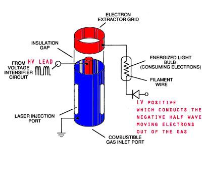
                        This "water spark plug" is the most basic and straight forward manifestation of Puriarch's patent #4394230, which was the slightly redrawn and patented again by Stanley Meyer's (his water plug). I have taken the liberty to add in a little piece I was "given"...(Let me first state that I have been up for over 24hrs now...on absolutely no drugs , something has compelled me to make this compilation and share it).
                        I now understand the importance of "splitting the positive...and let me share it with all you...this Water spark plug is bigger then many of you may imagine!

                        First, let me start with Puriarch...This is an illustration of his patent, which I have taken the time to highlight for your enrichment, the EXACT same specifics of this here experiment!!! Only, with a different inner electrode WATER!!!
                        On the left, the original...on the right my notes...


                        Now Meyer's


                        I hope that it clicks for everyone else now!!! We have all the parts now, lets uncover this and send it to all!! And, GOODNIGHT zzZZZ

                        Comment


                        • WoH!
                          A LOT of graphic work here Radiant... no wonder you were up so long...
                          nicely done man!
                          Are you saying that the positive is being "split" by the design of a HV positive charge on the water but then pulsed and air-gapped from the LV positive electrode (which then acts as an electron extractor)?
                          I think I get it... but want to make sure.
                          anyway.... nicely done.... are YOU fabricating this? Is anyone?

                          @Aaron... I went to review a vid you posted on Youtube... and found your account "suspended".
                          What's up with that???
                          Last edited by goldenequity; 08-27-2008, 05:00 PM.

                          Comment


                          • diode increases speed

                            Originally posted by Aaron View Post
                            Hi Lee,

                            What is it about adding components (diodes) that shortens the impulse time?

                            I agree with you but what is this telling us?
                            First of all, low voltage cannot move through the diodes until the voltage is lower on the cathode/output side. That means that the HV side must discharge across the gap and the diodes still won't open until the voltage drops below the LV source....is that your understanding?
                            I'm not pointing this out to you Lee, just posting this in general because so many people have a hard time believing me when I tell them the HV enters the diode before jumping a gap. And, I think it could be relevant to the time compression you're seeing on the scope when diodes are added.

                            The test that I'd like to see but I don't have the equipment for is to remove the diodes and monitor the voltage at the spark plug input. Add diodes and do same. I want to see if not only does the discharge happen faster, but the voltage increases beyond what the secondary outputs...(compression against diode when diode shuts off).
                            Agreed, it is difficult to observe something that is so fast and difficult to measure with basic equipment. The only point I would attempt to measure is across the cap which is essentially the LV primary winding. My digital scope goes potty when in proximity to the circuit let alone connected to it.


                            With a serious increase in the voltage instantaneously...as this jumps the gap, does it literally suck the current from the LV circuit offering a negative resistance for the LV to discharge into?
                            I'd like to see it disproved as much as proven because this will tell a lot.

                            Comment


                            • Plasma Ignition Patents

                              Download this file: Plasma Ignition Patents

                              That is a zip file with some patents I've studied. They happen to show almost everything I have done. Notes are below and also in a word doc in the zip file. Please read them thoroughly. I believe they will get most everyone on the same page.

                              FOR INFO VISIT THIS THREAD:


                              read every post before asking questions because the questions have probably already been answered.

                              Registration is free. If after 3 daysinfo @ esmhome.org and ask to be approved. Please do NOT private message any member here asking for access.Welcome to Knite, Inc.non-diodeOPEN UP THE GAP BIGGERUSE REAL HEARING PROTECTION AND VERY DARK SUNGLASSES when working with this plasma. X-rays are also emitted so use a lead suit if you want, I don't know how much of a concern it is at this level.
                              Sincerely,
                              Aaron Murakami

                              Books, Videos, ESTC Conference Info, Blog, etc. https://emediapress.com

                              Comment


                              • youtube banned my vids

                                Goldenequity,

                                Youtube has taken it upon themselves to permanently suppress and ban every single one of my videos and they refuse to comment on it. They won't respond to me no matter what.

                                Sincerely,
                                Aaron Murakami

                                Books, Videos, ESTC Conference Info, Blog, etc. https://emediapress.com

                                Comment

                                Working...
                                X