Announcement

Collapse
No announcement yet.

Bizzy's Bedini Machine aka Watson Machine

Collapse
X
 
  • Filter
  • Time
  • Show
Clear All
new posts

  • Bizzy
    replied
    Hallo Paul
    I had thought about using aluminum before. However it would have to be THICK so it wouldn't bend. But previously when I would bend thicker aluminum it would crack at the seem. I have thought about heating it at the bending point but never had a chance to try. Perhaps this would be a good a time as any to try.
    Thanks
    Bizzy

    Leave a comment:


  • wrtner
    replied
    Originally posted by Bizzy View Post
    I either need to find a better method to hold the magnets in place that will stiffen the zinc or i need to find a stiffer metal that isn't attracted to magnets.
    I cannot visualise the situation but a heavy alumium piece might do,
    possibly cut from the side of a scrapped aluminium saucepan hammered
    into shape.

    It is amazing how many things get built with a hard wood. A section from
    an old scrapped bannister rail is excellent.

    Leave a comment:


  • Bizzy
    replied
    A question

    Good morning
    Since I have been rebuilding my machine I have noticed some fatigue on various parts which I hadn't noticed before. Sometimes it just requires a slight adjustment here or there. However last night while I was tinkering I noticed a problem which has cropped up repeatedly.
    To hold my trigger magnets in place on the trigger wheel I have been using zinc flashing. I tried using steel at first but found the steel interfers with the magnetic flux too much and I was getting misfires on my switch. As a result I used the zinc because it is non ferris and isn't attracted to magnets. And yes i use the handy man's secrect weapon to hold the magnets in place

    My problem is that the zinc is not stiff enough and bends after a while. Last night I noticed some of the magnets were ready to fly off again so I had to retape them. I either need to find a better method to hold the magnets in place that will stiffen the zinc or i need to find a stiffer metal that isn't attracted to magnets. I will hoepfully post a pic of the assembly to give you a better dea of what I am talking about , but any suggetsions you could give me in the mean time would be greatly aprreciated.
    merci vielmals
    Bizzy

    Leave a comment:


  • Bizzy
    replied
    Originally posted by wrtner View Post
    It is good that the move is going well.

    What would be great would be a picture of the components and
    a picture of them temporarily strung together just for the photgraph.
    I still can't get a handle from your video on your gear.
    Paul-R
    Good morning
    This past weekend I started rebuilding my machine in the garage. I am using a smaller more compact table so i can just load it onto a trailer and take it to North Carolina when we move.
    This past weekend I got the shaft bearings and motor installed as well as the rotor and alternator. I need to make some tests in case I need to adjust anything before I install the switch.
    I have been taking a great many pictures of the unit as I am building. I hope to post some later this week.
    Bizzy
    Last edited by Bizzy; 08-13-2012, 04:59 PM.

    Leave a comment:


  • wrtner
    replied
    Originally posted by Bizzy View Post
    I also hope to post more pictures of the construction.
    It is good that the move is going well.

    What would be great would be a picture of the components and
    a picture of them temporarily strung together just for the photgraph.
    I still can't get a handle from your video on your gear.
    Paul-R

    Leave a comment:


  • Bizzy
    replied
    Update

    Good morning
    My wife and I visited the city down south where we are to be transfered and liked it. We even have a great deal of our things put away and threw out literally a TON of old stuff we had squirreled away for 19 years and would probably never use. We actually found the perfect house for us BUT... my company came back to me and said the money to transfer us won't be available until until next year


    Like many of you I am constantly getting ideas in my head and in particular about my machine. So to that end I decided to rebuild my machine on a trailer so that I can work on it now and just move it whenever they decide the time is right.
    I simply need to get a hitch on my truck next week so I can get my trailer home from my camp.
    Because I have already built it once before rebuilding should hopefully be easier. I also hope to post more pictures of the construction.
    Have a great day
    Bizzy

    Leave a comment:


  • Bizzy
    replied
    shaft coupling

    Originally posted by wrtner View Post
    Hold on to your horses.

    Don't throw the old shaft out. As I understand from you, the linkage
    widened so that there was a lot of slack in the coupling. i.e. every
    pulse, there was a bang as the slack was taken up.

    Check out the Chas Campbell system. Here, you have a motor driving
    an alternator using a DELIBERATELY slack pulley belt. It is the banging
    about which creates, God knows how, the excess energy.

    page 4
    http://www.free-energy-info.co.uk/Chapter4.pdf
    Hi Paul
    Yes you are exactly right I think the "banging" at each pulse does help creat energy. At the begining of that same chapter you mentioned by Patrick kelly. It goes into better detail of why that is the case. So I won't bore anyone with my feeble attempt to do so.
    That is why I used the shaft couplings that i did as described in the attached document
    If you look at the side view you will see the outter coupling fits over the inner coupling with bolts holding them in place to the respective shafts.
    the other part of the diagram shows the same coupling assembly but as if you were looking down the shaft. As you can see there is quite a bit of play between the inner and outer coupling so i get that "banging" like Chas Campbell got. In my case I was getting the impact from that pulse twice per revolution. The problem that I was having was with the bolt at the outter coupling as it held the coupling to the shaft to the alternator. The coupling itself was fine but the hole in the shaft is what was ripped open wider. Strangely enough the motor shaft was uneffected. But the alternator shaft may need more work

    Bizzy
    Attached Files
    Last edited by Bizzy; 07-25-2012, 05:46 PM.

    Leave a comment:


  • wrtner
    replied
    Originally posted by Bizzy View Post
    However in the course of the few years the hole was "pounded"
    wider by the bolt holding it in place.
    Hold on to your horses.

    Don't throw the old shaft out. As I understand from you, the linkage
    widened so that there was a lot of slack in the coupling. i.e. every
    pulse, there was a bang as the slack was taken up.

    Check out the Chas Campbell system. Here, you have a motor driving
    an alternator using a DELIBERATELY slack pulley belt. It is the banging
    about which creates, God knows how, the excess energy.

    page 4

    Leave a comment:


  • Bizzy
    replied
    Disassembly

    Good morning everyone,
    As most of you know it has taken me several years to be able to build my machine to where it is(or was) now. But it has taken just a few days to take it apart and start to box it for shipping. However in a way i am glad i did because i discovered some things I didn't notice before. The biggest problem I found was the steel shaft.
    Originally the 5/8 inch steel shaft had a 1/4 inch hole so I could connect it to the motor coupling. I never had any reason to check it before since it worked well once I built it. However in the course of the few years the hole was "pounded" wider by the bolt holding it in place. There was only a 1/8 inch peice of steel on either side of the shaft. I speculate that within another few weeks of running it would had broken off.
    Although I have started and stopped it probably hundreds of times over the past couple of years I speculate that the actual damage to the shaft happened when the machine actually started running properly. Which means it was pulsed twice per revolution at 5oo+ RPM.
    So I will have to try and re-enforce that when I rebuild the machine.
    Bizzy

    Leave a comment:


  • Bizzy
    replied
    Originally posted by Farmhand View Post
    Hi Bizzy, When you do set back up, you might like to try this if you haven't
    already tried it. The change is just the two diodes between the battery and cap
    and the motor drawing from the cap directly. The result should be that the
    capacitor can fluctuate above and below the battery voltage for the amount of
    the diode's voltage drop. So for instance if the diodes had a voltage drop of 0.5
    volts and the battery was at 12.5 volts the cap could go from 12 to 13 volts
    without really affecting the battery. If the cap is big enough then that might be
    enough energy to run the machine. 13 volts across a 30000uF capacitor is 2.535 joules
    and 12 volts in the same cap is 2.16 joules so there is 0.375 joules to play with
    without charging-discharging the battery. I think the principal can be used
    by different modes with voltage drop devices of some other nature maybe as
    well. It would be better if the cap didn't go below the battery voltage, but
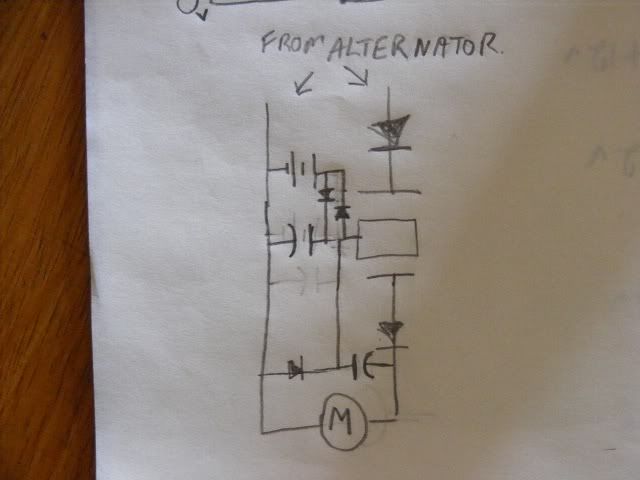
    I can't think of any way to do away with that left diode, maybe two diodes in
    series to the battery from the cap would help.


    I think I copied the part of your circuit correctly leaving out the alternator
    rectifiers. If not I apologize.

    Cheers
    Hi farmhand
    I saw the schematic you drew earlier but don't see it now. Regardless. yes you have the right idea about the switch and drew it correctly
    I have been thinking about doing something similar to what you described but wasn't certain if it would make a differance BUT in reading over your explination I think that has real merit. I will definately try this once I get set back up again in North Carolina.
    I also like the simpilcity of the way you arranged the diodes. Previosuly when i was thinking about the arrangement I was over thinking the whole idea and was actually thinking about retooling the switch itself. I will definately report back on this one thanks
    Bizzy

    Leave a comment:


  • Farmhand
    replied
    Hi Bizzy, When you do set back up, you might like to try this if you haven't
    already tried it. The change is just the two diodes between the battery and cap
    and the motor drawing from the cap directly. The result should be that the
    capacitor can fluctuate above and below the battery voltage for the amount of
    the diode's voltage drop. So for instance if the diodes had a voltage drop of 0.5
    volts and the battery was at 12.5 volts the cap could go from 12 to 13 volts
    without really affecting the battery. If the cap is big enough then that might be
    enough energy to run the machine. 13 volts across a 30000uF capacitor is 2.535 joules
    and 12 volts in the same cap is 2.16 joules so there is 0.375 joules to play with
    without charging-discharging the battery. I think the principal can be used
    by different modes with voltage drop devices of some other nature maybe as
    well. It would be better if the cap didn't go below the battery voltage, but
    I can't think of any way to do away with that left diode, maybe two diodes in
    series to the battery from the cap would help.


    I think I copied the part of your circuit correctly leaving out the alternator
    rectifiers. If not I apologize.

    Cheers

    Leave a comment:


  • Bizzy
    replied
    Good news Bad news

    Hello everyone,
    I wanted to give everyone an up date.
    the good news was that my machine has ran non stop for 9 days with no sign of slowing or lose of power. This has been a very exciting run
    The bad news is that I need to shut it down again because we are packing up our house so that we can move becasue my job is being transfered.
    Once we get settled into our new house I will begin to rebuild the machine and continue some other tests I have in mind.
    Take care
    Bizzy

    Leave a comment:


  • Bizzy
    replied
    sound

    Good morning
    I think that I have finally made a barrier that will arrest the sound enough for my wife to accept for long periods of time.

    So tonight I am going to turn it on and just let it run
    Bizzy

    Leave a comment:


  • Bizzy
    replied
    Originally posted by wrtner View Post
    The voltage does not show the work being done.

    It shows the pressure at which the current would flow out and do work if
    you connect a circuit on to it.

    By measuring the current in that circuit you would get the rate at which work
    is being done, i.e. the power.


    Also, on the subject of noise, it is very imprtant to avoid any holes.
    An architect told me that an oak door is a good noise break. Put a
    keyhole in it and it is often ruined.

    But there is nothing to beat masonry. If you are really annoyed, build
    it a little brick enclosure, not forgetting the base and ceiling and making
    sure that you have no holes or air gaps.
    Hi Paul
    I understand perfectly about the amperage. as i said i only used the voltage for the demonstration. I have tested the amperage and it is 5-6 at the alternator and at the motor. the problem I had with demonstrating the amperage production is that when the switch is turned on the power coming out of the alternator is not under load (I have tested the amperage under load from the alternator with varying speeds which is how I know the output amperage.
    Naturally at the motor side of the machine there is load so i could have shown amperage. But in this case I wanted to compare apples with apples or in this case volts with volts. The problem is the switch isolates the alternator from the motor so while it is running there is no direct load on the alterntor to show the amperage before the switch at the alternator only on the motor side of the machine.
    I finally got another multi meter and if I have time I can video the machine with a multimeter measuring amps but it would only be at the point of the motor
    As far as concrete I agree that would be best unfortunately my experiments are done in my basement and my wife would have a fit if I built a cement block wall in the basement. She already thinks I use too much cement and stone in things I build(part of my swiss heritage )
    Bizzy
    Last edited by Bizzy; 07-09-2012, 12:19 PM.

    Leave a comment:


  • Bizzy
    replied
    Originally posted by shylo View Post
    I think it's fantastic
    Hi Bizzy, you said in the clip that the battery was not" fast enough to keep up", so you put a cap parallel to it?
    I never thought of this, I've been trying to catch the spikes from shorting coils, but I am only getting some of the spike stored , the rest is going to waste.
    I hope it works for you
    shylo
    Hi Shylo
    Thanks

    Yes the cap battery combination in parrallel works great it combines the speed of the capacitor and the charge of the battery Thatcould be the answer you are looking for in your experiment. Just be sure the capacitor is big enough to handle the electricty you are using
    Bizzy

    Leave a comment:

Working...
X