This forum is preserved as a permanent archive. The community continues at eMedia Press.

Announcement

Collapse
No announcement yet.

Bedini Ferris Wheel Regauging Motor

Collapse
X
 
  • Filter
  • Time
  • Show
Clear All
new posts

  • Les_K
    replied
    Originally posted by graphitebone View Post
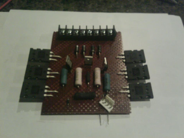
    just waiting on a few more parts.
    Nice work.
    I have noticed the three transistors and JB had them on his at the conference, could you tell me a little about that? What transistors are you using etc?

    Thanks
    Les

    Leave a comment:


  • graphitebone
    replied
    catching up

    just waiting on a few more parts.
    Last edited by graphitebone; 12-05-2011, 03:47 AM.

    Leave a comment:


  • Les_K
    replied
    Ok, Got a basic comparator circuit running. Had to go back to the circuit on page 47. Figured out how to change the Transistor and SCR over to fets. I then looked at the h11d1 and discovered it was pulling something like 30ma.
    Finally remembered a little electronics back in the old days called darlington pairs.
    With a MPSao6 in a darlington with the opto I was able to get the current way way down. I then attacked the Zeners and got them very close to the knee. so I am using a very small amount of power. I was very surprised to find out that I could get a very low current with a larger 3watt 5929 than with a smaller 1 watt zener. Been a long time since I did much analog so it has been a real brain worker.... the circuit is not what I would call stable though. It seems to drift a bit has some misfires and sometimes turns off and starts charging the cap before it is discharged to the battery voltage. Typically about 2 volts of the battery though. Anyway just an update.

    The main thing I wanted to ask though, (If your still around and watching John) is that I remembered that the wooden wheel at the conference had the outside coils with something like 3000 turns of #20 wire at 19 ohms. and the aircore had something 1100 turns. But I don't remember any of the rest of the numbers on the coils. I am (Can you believe it) thinking of another machine and would like to try the three ceramic setup. Could you tell us a little more about those coils John?

    Thanks
    Les

    Leave a comment:


  • Rl2003
    replied
    Got it Ron,
    Thanks,
    Nothing new to post yet, but I have picked up some new wire
    to start some larger coils. I should be able to post some results
    of what I learn once I get it all wired up.
    Mark

    Leave a comment:


  • Ron Chase
    replied
    Email

    Originally posted by Rl2003 View Post
    Brent, Ron and others that where at this years conference.
    Why is it that no schematic??? Nothing has been
    shared with this group that I know of, on the infomation for this
    thread. Did I miss all that?? We put up all kinds of pictures and
    videos from the first conference. Is there nothing to share. We can't
    help you trouble shoot your problems if we don't try the circuit.

    I would tend to agree with Ron, about the hall switch and the On time
    being to long. That was one reason I started to use a Opti switch.
    I have been able to get the draw down to about .05 amps (no heat at all)
    and still have some charging going on/ plus I am back charging the run batteries,
    some as well. This is all to get the system tuned to the set up I have. Then
    I will slowly open the slot for the Opti switch and get the RPM to charge and
    balanced it out some more. As it charges much better with a slightly longer
    On time.
    More at a later time.
    Mark

    Mark, check your email on this forum.

    Ron

    Leave a comment:


  • Ron Chase
    replied
    Coil Winder?

    This may be the first time a Bedini Ferris Wheel has been used to wind extra wire on its own slave coils. With the welding rod cores and support plates glued in place I couldn't use my small lathe for winding so I was looking for an alternative and realized I had the perfect winder right in front of me. A short length of ABS pipe, duct tape, spacer's and a little TLC did the job. I did increase the wheel RPM to speed things up.

    In the pictures you will notice a load resistor across the 15,000uF cap to hold the voltage measured at the the cap to around 30V. With just the center coil hooked up the current draw from the power supply is 600mA @ 36V. With the slave coils also hooked up its around 800mA @ 36V. Wheel diameter is 5 feet.

    Next up is JB's comparator cap dump circuit.
    Attached Files

    Leave a comment:


  • BrentA929
    replied
    John K,

    We just used the cap off our big wheel. It is a 17000uF cap. Probable over-kill, but we just wanted to try a few things. This being our first experience with solar panels, sure makes you very dependent on the weather. Cloudy days will really bring you down! Ha!


    Brent

    Originally posted by John_K View Post
    Hey Brent,

    Good stuff. Very similar to my solar setup. What size cap are you using?


    John K.

    Leave a comment:


  • John_K
    replied
    Originally posted by BrentA929 View Post
    Hey guys,

    Just a little test we ran on the comparator circuit...

    Here is a video of what we did.


    Enjoy, Brent
    Hey Brent,

    Good stuff. Very similar to my solar setup. What size cap are you using?


    John K.

    Leave a comment:


  • Ron Chase
    replied
    Solar Panels Run Comparator

    Very Cool! You guys get to do all the fun stuff. I'm not far behind.

    Ron

    Leave a comment:


  • BrentA929
    replied
    Comparator Circuit

    Hey guys,

    Just a little test we ran on the comparator circuit...

    Here is a video of what we did.


    Enjoy, Brent

    Leave a comment:


  • BrentA929
    replied
    Bedini GT3 "Junior"

    @Ron,

    Thanks for your most recent explanation. I was hoping to get some different resistor values today, but have been to busy. Will have to wait till next week...


    @Alex,

    Sorry we didn't take your suggestion earlier when you recommended it. Part stubborn and part lazy! Anyway thanks for your help!


    @Mark,

    I'm a little surprised too that no one has posted any photos from the last conference. Maybe someone will post some soon! We didn't get very many good ones...


    @Dave,

    Yes we still have the scope. I agree, we are probably pushing the transistors to hard and will try some new values next week. I have a few ideas and will definitely try the scope idea...


    @Les K,

    Yes, that last video is with the SCR zener LED dump circuit. Hope to have the comparator circuit on the big wheel next week as well.


    Did I leave anyone off? Anyway, thanks guys for all your help! It is nice to be apart of such a helpful bunch. Now, if we just weren't so ignorant when it came to electronics! Still learning...


    Brent

    Leave a comment:


  • Les_K
    replied
    Originally posted by BrentA929 View Post
    @All,

    Not much to report, other than some frustrations with the Bedini/Cole circuit...

    We can't seem to get a grasp of why the resistors are getting so HOT (200+ degrees) and why when a neon is attached across the transistors, one side will flash! Do these issues have something to do with each other?


    Here is a video showing what is going on...Bedini/Cole circuit issues video


    Real hard to run any prolonged tests until we can figure this out! HELP!


    Thanks, Brent


    P.S. Oh and BTW, the circuit doesn't get even remotely warm on a smaller coil nor do the neons flash. What are we missing? Bigger switch? More transistors?
    Hey brent,
    Does it heat up with the old scr pulser? If not I would say the problem is that
    your fet's are not properly isolated from the rest of the circuit.
    Take another look at page 47 of your FEG book and never forget this one little equation

    JOHN BEDINI :== Pure Genius

    Also take note Brent that the h11d1 is fully capable of driving the fets without an extra transistor.
    I ran some tests on my circuit and I wish I could get a vid for you but I have not been able to replace my camera.

    Les

    Leave a comment:


  • Ron Chase
    replied
    Schematics

    Hi Mark,

    I think there is some reluctance to post the schematic (motor control and comparator cap dump) based on pictures taken of JB's Bedini/Cole circuit that he had at the conference. He may be selling motor control modules based on the "highly modified" Bedini/Cole circuit so we don't want to compromise that effort but there is great value to experimenting with this modified circuit so maybe JB would allow sharing the circuit between members privately.

    JB checks this thread regularly so perhaps we'll hear from him.

    Ron

    Leave a comment:


  • Web000x
    replied
    Originally posted by BrentA929 View Post
    @All,

    Not much to report, other than some frustrations with the Bedini/Cole circuit...

    We can't seem to get a grasp of why the resistors are getting so HOT (200+ degrees) and why when a neon is attached across the transistors, one side will flash! Do these issues have something to do with each other?


    Here is a video showing what is going on...Bedini/Cole circuit issues video


    Real hard to run any prolonged tests until we can figure this out! HELP!


    Thanks, Brent


    P.S. Oh and BTW, the circuit doesn't get even remotely warm on a smaller coil nor do the neons flash. What are we missing? Bigger switch? More transistors?
    Do you guys still have that scope?

    You are definitely pushing your transistor bases to the max if you are seeing that type of heating.

    I have a feeling that John (correct me if I'm wrong) wasn't running his transistor bases that hard. You should look at the waveform of the coil on the scope and decrease the base resistance while trying to match John's waveform.

    @Rl2003
    I have some photos from the conference. Give me a little bit and I'll post them.

    Dave

    Leave a comment:


  • Rl2003
    replied
    Exclusive To Conference Participants??

    Brent, Ron and others that where at this years conference.
    Why is it that no schematic??? Nothing has been
    shared with this group that I know of, on the infomation for this
    thread. Did I miss all that?? We put up all kinds of pictures and
    videos from the first conference. Is there nothing to share. We can't
    help you trouble shoot your problems if we don't try the circuit.

    I would tend to agree with Ron, about the hall switch and the On time
    being to long. That was one reason I started to use a Opti switch.
    I have been able to get the draw down to about .05 amps (no heat at all)
    and still have some charging going on/ plus I am back charging the run batteries,
    some as well. This is all to get the system tuned to the set up I have. Then
    I will slowly open the slot for the Opti switch and get the RPM to charge and
    balanced it out some more. As it charges much better with a slightly longer
    On time.
    More at a later time.
    Mark
    Last edited by Rl2003; 09-08-2011, 03:48 PM. Reason: missing word

    Leave a comment:

Working...
X