-
cap dump
Here is one old version I did:

Bedini's patent cap dump without scr -

Older mechanical switch timed by pulley using isolated recovery winding:

Leave a comment:
-
Thanks Aaron.Originally posted by Aaron View Post
Seems the SCR is staying opened after the cap reaches some voltage.
I have zener 16V along with a led diode to trigger the scr and the led lights all the time ... it is dim though. The cap bank is ~70mF and more have arrived to make it ~130mF.
I have tried also neon controlled SCR, transistor breakdown.
I think you mentioned earlier that you got best result with mechanical switch. So I want to try this.
I am using different methods to charge the caps, bedini style PC fan, SS SSG, joule thief (currently). I am experimenting and learning basically as I am not an electrical engineer.
Now that I am writing this I got some ideas what I might have done wrong. So I will post later.
My relay is of this type
Last edited by cdjambov; 06-22-2016, 01:55 PM.Leave a comment:
-
relay cap dump
This isn't the full schematic but this could accomplish it - this was for cap dump to an ignition coil:Originally posted by cdjambov View Post

You need a dpdt relay and connect cap to common and NC - NC would be from the SG or SSG output. Then you need something to trigger the relay coil by either time or cap voltage. Triggering coil will disconnect cap from SG and then dump to battery instead of ignition coil like you see in the diagram.
Is there a reason you want to use a relay instead of an SCR?Leave a comment:
-
Hello everyone
Can someone pls post circuit of the cap dump with relay instead of scr ?
I have tried several times with different way of connecting the relay .. but seems I am missing something.
Thanks.Leave a comment:
-
Hi Twinbeard,Originally posted by twinbeard View Post
I am curious about the not so good battery producing such a different result with the pulse circuit. Is this because most of the spike is being absorbed by the battery or what? Do your neons fire when this is going on? (I've seen my neons fire when a not so good battery is connected. I think because the battery isn't capable of absorbing the spike since it is bad.)
Thanks,
ChrisLeave a comment:
-
Hi Carroll thanks for getting back to me and thank you for your time !
As you can see I am closedopenLeave a comment:
-
Hi Virus,
What do you mean by "stays open"? Do you mean the SCR burns out and no longer works? Or do you mean the SCR turns on and won't turn off? I am not really trying to pick on you but the term open or stays open is misused a lot on this forum. People who actually work in electronics only talk about an electronic device being open when they mean it has burned out and is open inside. Think of the old knife switch you used to see in the movies. When the blade of the switch is up the switch is open. When you put the blade down you close the switch and complete the circuit. Electronic devices turn on and off, they do not open and close.
In your circuit if the SCR is staying on after first turning on it is probably because there is still current flowing from the cap into the battery. SCR's will not turn off if there is still current flowing through them. You have to design your circuit so the cap will discharge to the point where no current can flow into the battery in order for the SCR to turn off and wait for the neon to fire again. Unless you have a pretty slow charge rate on the cap it is very difficult to get it to work with only a neon and SCR. You might try increasing the size of your cap and see if that helps.
Respectfully,
CarrollLeave a comment:
-
Cap Dump Video
Hi All,
I made a short video of the fan with the cap dumper circuit:
Cap Pulser Circuit - YouTube
Enjoy,
TwinbeardLast edited by twinbeard; 02-03-2012, 08:34 AM.Leave a comment:
-
I am referring to the scr/zener circuit I posted a schematic revision for in post #95 of this thread:Originally posted by Guruji View Post
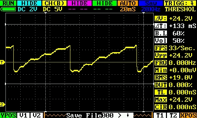
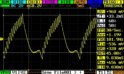
I am considering adding the LED to the circuit for visible dump indicator, while moving the voltage down a bit on the zener. Currently I am using two 2000 microfarad 15V caps in series, and a 12.1V zener. It seems about the minimum value for the circuit, based on the waveform. Increasing cap values will lower dump frequency, as well as the current dumped across the battery. I paralleled in 3250 microfarads more last night, which had the dump frequency at about 2Hz.
It makes me want to really fine tune this to highest frequency dump, and have the caps dump into the primary of a small exciter instead of a battery, and see what happens.
Enjoy,
TwinbeardLeave a comment:
-
solar
Hey Totalas,Originally posted by totoalas View Post
Forgot to speak on the solar. All of this is running from solar. I have 640W of panels charging a 1600Ah @12V battery bank. There is a 1F 20V cap paralleled with the battery bank. My benches are wired with 12V busses, which I run all of my experimental work on.
So yes, it works well from solar I have another device I will be showing soon that is designed to be powered directly by a dedicated panel, eliminating the charge controller
and battery bank in between, and a Uni-Solar PVL-68 to power it. Way too much power for what the device draws, however, but the smallest in Uni-Solar's line of flexible thin film panels. Perhaps one of their roofing tiles would be appropriate...
In any case, the panel charges a big cap bank, which drives the device in the event of very low light conditions.
Enjoy,
TwinbeardLeave a comment:
This forum is preserved as a permanent archive. The community continues at eMedia Press.
- If this is your first visit, be sure to check out the FAQ by clicking the link above. You may have to register before you can post: click the register link above to proceed. To start viewing messages, select the forum that you want to visit from the selection below.


 May I know the input current and maybe try with a solar as well???
Leave a comment: