Announcement

Collapse
No announcement yet.

Who performs the first longitudinal Moon-Bounce in history?

Collapse
X
 
  • Filter
  • Time
  • Show
Clear All
new posts

  • lamare
    replied
    Originally posted by Kokomoj0 View Post
    Also on a side note, I believe tesla said that there is no energy in matter and that matter gets all its energy from the environment. In what respect did he mean that? Is he looking at energy as power output or power that can be extracted? I mentioned that to a friend yesterday and the reply was that there is energy in matter such as wood can burn etc and I realized that tesla must have had some very specific set of circumstances he was referring to. Yet if it proves einstein wrong then you would think it applies to al matter generally. If you are up on that one too, I have not found how tesla was applying that?
    I don't know how Tesla looked at it, but from my point of view matter is essentially ether in a specific steady-state flow of motion, a flow of motion along some kind of vortex pattern in some kind of medium with fluid-like properties. As I posted here, we have no way to know what the ether is really like. All we can investigate is it's properties in terms of the way the elctromagnetic fields can propagate trough it:


    The problem is that there is no way to really know this from an Engineering point of view, because all we know is that everything that exists in the ether is:

    1. steady state flows;
    2. longitudinal waves;
    3. vortexes.

    All that is [physical], is a combination of these three phenemenon taking place in a substance called ether, with fluid-like properties in terms of the way it behaves with regard to electrical phenomena taking place.

    This is all we really know about it's properties from an Engineering point of view:
    A Dissident View of Relativity Theory by William H. Cantrell, Ph.D. :

    "Given that the nothingness of a perfect absolute vacuum is bestowed with the physical properties of a permittivity, e_o 8.854 pF/m, a permeability, m_o 4p x 10-7 H/m, and a characteristic impedance of 377 ohms, is the concept of an aether really that outlandish?"

    Now the problem is that the only way we can interact with the ether is trough electro-magnetic phenomena in all the various ways these occur. So, how are we going to know what the ether is like, if we can only investigate it's electro-magnetic properties?

    Now even though you cannot know what the ether really is made of, you can mathematically define an ideal "superfluid" and match it's properties to the known properties of the actual ether (permittivity, permeability and characteristic impedance) and then you have a theoretical model of the ether with which you can describe everything that we can know about the ether from an engineering point of view, because we can only interact with the ether by means of electro-magnetic interactions.

    And that is basically what Paul Stowe did:

    A Foundation for the Unification of Physics
    We will start by defining a single vector entity (a basic quantum [not a photon, neutrino, graviton]). The fundamental properties of this quantum entity is; it has momentum P, occupies space consisting of volume s, obeys Newton laws of motion, exerts no force, and no external forces are exerted on it. This quanta therefore move through four dimensional space (x,y,z,t) at velocity V and has an apparent mass m, equal to (P/V).

    Next, a population n of these quantum, having random orientation, occupying volume s', such that there is spacing between the entities, results in a system described by basic kinetic theory (without friction or interacting forces {a superfluid state}). Since each quantum, by definition, has an intrinsic momentum P, the system momentum p_s, becomes simply n[p].

    A direct approach for defining such a system's total energy is in terms of total quanta interactions directly. In any such system, these interactions, are directly proportional to the average travel distance between collisions (called the mean free path {MFP}) also known as the interaction length l, and the momentum of the colliding quantum. This property directly defines the lagrangian action parameter h of the system.
    So, while we have no idea what the ether really is made of, we now have a model for the ether in terms of some very simple but "made up" elemental entities that do not actually exist. It is just a tool to describe a fluid-like medium in terms we are familiar with. And since we have no idea what the ether is really made of, this is just as good as any other model you can make of the ether. And I really like this one, because it is very simple and therefore elegant.

    All right.

    Now with this model, all energy is expressed in terms of the sum of the momentum of a bunch of these non-existing entities with which the medium can be described.

    And since matter is some kind of flow in the ether, all the energy in matter can be described in terms of the momentum of the fluid-like medium in which it exists, which would be the environment.
    Last edited by lamare; 11-09-2011, 01:34 PM.

    Leave a comment:


  • lamare
    replied
    Originally posted by Kokomoj0 View Post
    I gave that some thought and what I find confusing is the E field is claimed to share both the transverse and longitudinal waves seemingly at the same time. How do we reconcile the same field travelling at 2 different speeds at the same time? or do I misunderstand the principle? I believe the dielectric component is the E field? Maybe the question to ask is what field is the dielectric longitudinal wave being represented as?
    As far as I can tell, there are actually two kinds of transverse waves.

    1. A 'real' transverse wave which can only occur ad the boundary between two media, like wire and air/vacuum, which is what is known as "the near field".

    2. Some kind of rotating vortex in the ether, which is known as "the far field".

    So, close to what Meyl wrote, it appears as if with the radiation of transverse waves, you have a "real" transverse wave in the vicinity of the antenna, which turns into some kind of "moving vortexes" further away from the antenna. After all, you cannot have "real" transverse waves in a fluid, only at the boundary between two fluids or gases with a dfferent density.

    I posted some on this before:

    Originally posted by lamare View Post
    As far as I can tell, Tesla regarded EM waves as being "just" transversal electro-magnetic waves, just like the kind of waves that travel on a pond when you throw a rock in there. If that is what he was rejecting, I totally agree with him, because you cannot have transversal waves inside a fluid. Not in water and also not in the ether. Only at the border of two media with a different density you can have classic transversal waves, IMHO. So, in that sense I agree with Tesla.

    However, there is a third way waves can occur, both in fluids as in the ether, which are waves that literally run in circles, or, around the surface of some kind of vortex. So, you cannot have actual transversal waves inside the ether, but you can have localized standing waves making some kind of bubble inside the fluid. And such bubbles, vortexes, are actually what we call particles and which are the cause for the well known wave-particle duality, which forms the basis for Quantum Mechanics:

    Introduction to quantum mechanics - Wikipedia, the free encyclopedia
    In 1924, Louis de Broglie proposed the idea that just as light has both wave-like and particle-like properties, matter also has wave-like properties. The wavelength, λ, associated with a particle is related to its momentum, p. [...] The relationship, called the de Broglie hypothesis, holds for all types of matter. Thus all matter exhibits properties of both particles and waves.
    In the double-slit experiment as originally performed by Thomas Young and Augustin Fresnel in 1827, a beam of light is directed through two narrow, closely spaced slits, producing an interference pattern of light and dark bands on a screen. If one of the slits is covered up, one might naively expect that the intensity of the fringes due to interference would be halved everywhere. In fact, a much simpler pattern is seen, a simple diffraction pattern. Closing one slit results in a much simpler pattern diametrically opposite the open slit. Exactly the same behaviour can be demonstrated in water waves, and so the double-slit experiment was seen as a demonstration of the wave nature of light.
    The diffraction pattern produced when light is shone through one slit (top) and the interference pattern produced by two slits (bottom). The interference pattern from two slits is much more complex, demonstrating the wave-like propagation of light.

    The double-slit experiment has also been performed using electrons, atoms, and even molecules, and the same type of interference pattern is seen. Thus all matter possesses both particle and wave characteristics.
    So, there you are. Tesla was right in that there cannot be classic transversal waves trough the ether, but it appears he simply never considered the possibility that EM waves could actually consist of some kind of vortex-like structure along which standing electro-magnetic waves can and do propagate trough the ether.

    And actually, in the area just around a transmitter antenna the fields have different characteristics than further away from an antenna. Remember what I said about the possibility of having transversal waves at the border of two media? How about the border between antenna and the air?

    This distinction is known as "near field" versus "far field":

    Near and far field - Wikipedia, the free encyclopedia
    The "far-field", which extends from about two wavelengths distance from the antenna to infinity, is the region in which the field acts as "normal" electromagnetic radiation. The power of this radiation decreases as the square of distance from the antenna, and absorption of the radiation has no effect on the transmitter. By contrast, the "near-field", which is inside about one wavelength distance from the antenna, is a region in which there are strong inductive and capacitative effects from the currents and charges in the antenna, which do not behave like far-field radiation. These effects decrease in power far more quickly with distance, than does the far-field radiation power.
    Now re-read Tesla's paper with that in mind.....

    So, in essence, Tesla did not realise that there was such a thing as a near field and a far field. And actually, modern science literally makes "things" known as "virtual photons" up in order to hide the fact that they don't have the slightest idea what they are really talking about:

    In the quantum view of electromagnetic interactions, far field effects are manifestations of real photons, while near field effects are due to a mixture of real and virtual photons. Virtual photons composing near-field fluctuations and signals, have effects which are far shorter range than do real photons.
    Yes, that's what it says. Near field effects are due to a mixture of something real and something completely made up aka "virtual", which is literally another word for "imaginary" or "not real".

    Update: Prof. Meyl shows this very nicely in his "Wireless Tesla Transponder":


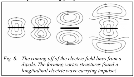
    In the text books one finds the detachment of a wave from the dipole accordingly explained. If we regard the structure of the outgoing fields, then we see field vortices, which run around one point, which we can call vortex center. We continue to recognize in the picture, how the generated field structures establish a shock wave, as one vortex knocks against the next [see Tesla: 1].
    Thus a Hertzian dipole doesn’t emit Hertzian waves! An antenna as near-field without exception emits vortices, which only at the transition to the far-field unwind to electromagnetic waves.
    However, the accompaning explanation sucks, because IMHO the far-field actually consists of vortices, "particles" with that mysterious wave-particle duality, so he may have to re-do some of his homework.
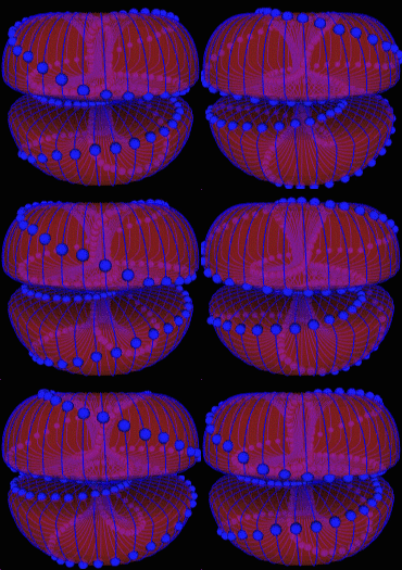
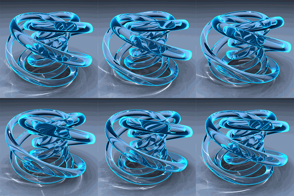
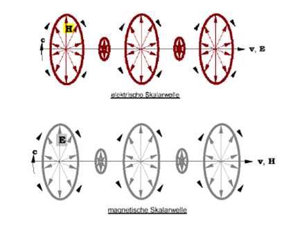
    So, the way I see it, you get some kind of vortexes or "smoke ring" like structures in the far field, which may look something like this:


    So, with electromagnetic waves, you have essentially some kind of rotation in the ether, whereby the fluid runs in circles/spirals, of course in the direction the variation of the ether pressure is pointing to, wich is the electric field.

    So, the electric field runs around in circles/spirals and that is what we call the magnetic component.

    Paul Stowe (some of his work here: Directory contents of /pdf/Reference_Material/Paul_Stowe/) has developped a model in which he describes in terms of "the aether populational momenta (p)". He describes magnetism as the Curl of this momenta:

    Curl (mathematics) - Wikipedia, the free encyclopedia
    In vector calculus, the curl (or rotor) is a vector operator that describes the infinitesimal rotation of a 3-dimensional vector field. At every point in the field, the curl is represented by a vector. The attributes of this vector (length and direction) characterize the rotation at that point.

    This is what he mailed me some time ago:

    I have determined that in my opinion all of physical processes can be defined in terms of the aether populational momenta (p). Such that,

    Force (F) -> Grad p
    Charge (q) -> Div p
    Magnetism (B) -> Curl p

    Gravity for example is Grad E where E is the electric potential at x. This resolves to Le Sagian type process as outlined in the Pushing Gravity models. The electric potential E in turn is created by charge which is Div p...

    My model is a direct extension of Maxwell's vortex model of interacting rings (the smoke ring model).
    I have been able to define all fundamental constants in terms of basic parameters, including the gravitational constant G. Further, G is, within this system, seamlessly integrated to all others, fitting into a unified system.

    The key to this system's definition is the realization that charge is fundamentally a result AND the measure of the compressibility of Maxwell's aether. See: The nature of Charge - Paul Stowe for futher details on this. This is a logical and natural extension of Maxwell work (Ref: http://vacuum-physics.com/Maxwell/maxwell_oplf.pdf )

    Quantity SI Conversion Factor to Maxwell's Ether Based Units

    Code:
    Length meter   (m)                  meter(m)
    Mass Kilogram  (kg)                 Kilogram (kg)
    Time Second    (sec)                second (sec)
    Force Newton   (Nt)                 kg-m/sec^2
    Energy Joules  (J)                  kg-m^2/sec^2
    Power Watts                         kg-m^2/sec^3
    Action         [h] (Planck's Const) kg-m^2/sec
    Permitivitty   [z] (Q^2/kg-m^3)     kg/m^3 {1}
    Permeability   [u] (kg-m-sec^2/Q^2) m-sec^2/kg {2}
    Charge         [q] (Coulomb)        kg/sec
    Boltzmann's    [k] (J/°K)           m-sec
    Current        [I] (Amp)            kg/sec^2
    Electric Field [E]                  m/sec
    Potential      [V] (Voltage)        m^2/sec {3}
    Displacement   [D]                  kg/m^2-sec
    Resistance     [R] (Ohms)           m^2-sec/kg
    Capacitance    [C]                  kg/m^2
    Magnetic Field [H] (Henries)        m^2
    Magnetic Flux  [B] (Gauss)          (dimensionless)
    Inductance     [L]                  m^2-sec^2/kg
    Temperature   [°K] (Kelvin)         kg-m/sec^3
    
    {1} - density
    {2} - modulus
    {3} - Kinematic Viscosity
    The basic physical quantities in this system are the medium properties identified by Maxwell in his 1860-61 "On Physical Lines of Force". We quantify the mean momentum (quanta) [Ăź], characteristic mean interaction length (quanta) [L], the root mean speed [c], and a mass attenuation coefficient [Âż].

    Their values are,

    Ăź = 5.154664E-27 kg-m/sec
    L = 6.430917E-08 m
    Âż = 3.144609E-06 m^2/kg
    c = 2.997925E+08 m/sec

    In other words, all of the major observed and measured constants of physics can be derived from the above terms.
    Last edited by lamare; 11-09-2011, 01:33 PM.

    Leave a comment:


  • Kokomoj0
    replied
    Originally posted by lamare View Post
    In essence, it's a matter of rotational movement of the ether in the case of the magnetic component versus straight movement in the case of the dielectric component.

    The magnetic component travels a netto path of half a circle, pi * r, while the dielectric component travels straight trough the centre of the circle, 2 * r. The division of these renders pi/2. In other words: the path the magnetic component has to travel is pi/2 times as long as the path the dielectric component has to travel. The magnetic component takes a detour, while the dielectric component does not....

    I gave that some thought and what I find confusing is the E field is claimed to share both the transverse and longitudinal waves seemingly at the same time. How do we reconcile the same field travelling at 2 different speeds at the same time? or do I misunderstand the principle? I believe the dielectric component is the E field? Maybe the question to ask is what field is the dielectric longitudinal wave being represented as?

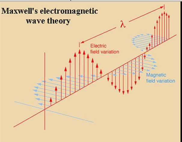
    transverse


    longitudinal


    and here are some measurements taken on the dome of meyls unit that may interest you?

    Last edited by Kokomoj0; 11-09-2011, 07:25 AM.

    Leave a comment:


  • lamare
    replied
    Originally posted by Kokomoj0 View Post
    I would think that the you would be able to at least get the near the rail voltage for unmoduated rf, but wouldnt you have to match it then drive the ball dierctly at such a high frequency? The nice thing is that it would be very directional but may require some kind of tracking to keep it on target too... This can get quite involved real quick. UNfortunately I have very little expereince with super high freq microwave baluns.

    Is that your back yard?

    If you are using a solid sphere wouldnt you stil need to account for the propagation velocity of the ball and transmitting elements?

    Also on a side note, I believe tesla said that there is no energy in matter and that matter gets all its energy from the environment. In what respect did he mean that? Is he looking at energy as power output or power that can be extracted? I mentioned that to a friend yesterday and the reply was that there is energy in matter such as wood can burn etc and I realized that tesla must have had some very specific set of circumstances he was referring to. Yet if it proves einstein wrong then you would think it applies to al matter generally. If you are up on that one too, I have not found how tesla was applying that?

    The photograph is just one I found on the net..

    And you are right, I may have to account for the slower propagation speed in metal. IIRC, Dollard measured something like 1.25 x c with the mantle of his coax cable, which is a mesh-like structure filled with a dielectric. Wheatstone measured a propagation speed of 1.53 x c IIRC, and he used straight wires if I'm not mistaken.

    Maybe I can find something on then net about what kind of correction factors are normally used with antenna design to account for the slower propagation in/around a metal.

    Leave a comment:


  • Kokomoj0
    replied
    Originally posted by lamare View Post
    Hi all,

    Since the distance between the Earth and the Moon is on average 384,400 km, on average we would have a return path of over 750,000 km, which would take more than 2.5 seconds at the speed of light, which is the speed with which EM waves propagate. However, longitudinal waves could make the round-trip in just 1.6 seconds, a difference of 0.9 seconds!

    that and since the speed of light is accepted, (more like worshiped), if you can set up a standard xmitter/rec right beside the tesla transmitter/receiver you could compare them side by side and use the known light speed to measure the exact distance of the moon only seconds before or after you shot the tesla signal at it and get a precise measurement.

    That would be quite convincing I would think.

    Maybe use 2 pickups one on the dish and pull one off of the signal strength meter of the radio then run them both to whatever you choose for a timing device.

    Then again I suppose you could get fancy and send/rec a tone burst.

    Leave a comment:


  • Kokomoj0
    replied
    Originally posted by kitcar View Post
    Arend , I met a guy from the USA who is replicating tesla/ Meyls magnifying transmitter sets for a 3rd of the price with 1 watt transmission, (now upscaling to 500watt.) He is selling the 1w sets with alu ball antenna's for 300usd, meyl charges 800 euro or so.

    He gets 1.2 times C on a resonating frequencies somewhere between 4-8 Mhz.
    He verified that the scalar resonant frequency is related to length of wire in the coil, and speed of light times 1.2
    He also noticed the overunity effect at the receiver but so far hasnt explained me in detail about it.

    I have my doubts regarding the Meyl sets like you and this german set out Meyls errors: Skalarwellen.

    This is just a remark regarding the earlier posts in this topic.
    Tesla's 1.54 factor (12HZ from tesla / 7.8Hz schumann resonance)
    is close to pi/2 but these 2 values seem to be mixed up in many stories I read.

    Im also from holland
    Thats very interesting.

    You know that may be propagation delay, something that may be interesting to look into.

    From what I have seen so far mostly from the Dollar Lindemann lectures is that twekaing a tesla coil to be used as a transmitter from the design up can be very involved and there are no guidelines or land marks to be used for markers on where we should compromise and where we shouldnt.

    Its impossible to get all the building parameters ideal. (unfortunately)


    Do you have a link to that guys site or some way I could contact him? I would love to see what he has to offer.

    I could use a 25kw unit! LOL

    Leave a comment:


  • Kokomoj0
    replied
    Originally posted by lamare View Post
    I have no idea at this moment how to calculate voltages on the antenna. Have to figure that out. It is an interesting question, though.

    [CENTER]
    I would think that the you would be able to at least get the near the rail voltage for unmoduated rf, but wouldnt you have to match it then drive the ball dierctly at such a high frequency? The nice thing is that it would be very directional but may require some kind of tracking to keep it on target too... This can get quite involved real quick. UNfortunately I have very little expereince with super high freq microwave baluns.

    Is that your back yard?

    Lambda : 19,33 cm.
    Diameter large sphere: 29,00 cm.
    Diameter small sphere: 9,67 cm.
    Length feed pipe: 4,83 cm.
    Length whip: 14,50 cm.
    If you are using a solid sphere wouldnt you stil need to account for the propagation velocity of the ball and transmitting elements?

    Also on a side note, I believe tesla said that there is no energy in matter and that matter gets all its energy from the environment. In what respect did he mean that? Is he looking at energy as power output or power that can be extracted? I mentioned that to a friend yesterday and the reply was that there is energy in matter such as wood can burn etc and I realized that tesla must have had some very specific set of circumstances he was referring to. Yet if it proves einstein wrong then you would think it applies to al matter generally. If you are up on that one too, I have not found how tesla was applying that?
    Last edited by Kokomoj0; 11-08-2011, 03:34 AM.

    Leave a comment:


  • lamare
    replied
    Small scale proof of concept for antenna with WiFi.

    I just realized that when people want to experiment with this antenna design, it could easily be scaled down for the 2.4 GHz band, so you can use a wifi device, such as a linksys Linux router, for a proof of concept for longitudinal communication.

    Since the dimensions for that are much smaller, construction of an antenna is much easier to do. And if your only aim is to experiment with this over a short distance, you don't have to worry too much about error margins.

    The ideal dimensions for a 2.4 GHz antenna would be:

    Lambda : 19,33 cm.
    Diameter large sphere: 29,00 cm.
    Diameter small sphere: 9,67 cm.
    Length feed pipe: 4,83 cm.
    Length whip: 14,50 cm.

    Here is some more information on a DIY WiFi antenna:
    Homebrew 2.4 GHz 14 dBi Wide Angle Sector antenna

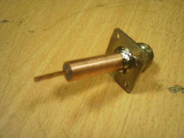
    With a detail on how to construct the feedline, which is called a balun:

    Have fun!

    Last edited by lamare; 11-07-2011, 10:52 PM. Reason: oops. radius should be diameter

    Leave a comment:


  • kitcar
    replied
    Arend , I met a guy from the USA who is replicating tesla/ Meyls magnifying transmitter sets for a 3rd of the price with 1 watt transmission, (now upscaling to 500watt.) He is selling the 1w sets with alu ball antenna's for 300usd, meyl charges 800 euro or so.

    He gets 1.2 times C on a resonating frequencies somewhere between 4-8 Mhz.
    He verified that the scalar resonant frequency is related to length of wire in the coil, and speed of light times 1.2
    He also noticed the overunity effect at the receiver but so far hasnt explained me in detail about it.

    I have my doubts regarding the Meyl sets like you and this german set out Meyls errors: Skalarwellen.

    This is just a remark regarding the earlier posts in this topic.
    Tesla's 1.54 factor (12HZ from tesla / 7.8Hz schumann resonance)
    is close to pi/2 but these 2 values seem to be mixed up in many stories I read.

    Im also from holland
    Last edited by kitcar; 11-07-2011, 11:07 PM.

    Leave a comment:


  • lamare
    replied
    Originally posted by Kokomoj0 View Post
    @lamare

    nice concept and design.

    you will be able to fine tune it with the pipe I presume.

    2 questions....

    What kind of voltage do you predict on the node?

    and how do you plan to switch it from the transmission mode to receiver mode?
    I have no idea at this moment how to calculate voltages on the antenna. Have to figure that out. It is an interesting question, though.

    In principle the antenna design works exactly the same as a normal whip antenna of 1 1/4 lambda from the transmitter / feedline's point of view. The only difference is the geometry which is designed to generate longitudinal dielectric waves instead of transversal waves. The antenna should work both as a transmitter and as a receiver antenna equally well.

    And since with a moonbounce we have a return time of about 1.6 seconds, we can transmit a signal for about 1 second after which we have "plenty" of time (about 0.9 seconds) to release the TX button and receive the signal bouncing of the moon trough the same antenna and tranceiver. So, for the actual experiment we only need one antenna and one transceiver, which is very nice, because those 25 meter dishes do not come in large quantities.

    At the moment, I am investigating the possibilities to realize an antenna for the 1296 radio amateur frequency which is "reserved" for moon-bouncing activities. Since in The Netherlands there are no ERP rules and a maximum of 120 Watt output power is allowed for 1296 MHz, we can kick some a** with this 25 meter dish, that's for sure.

    However, I still have to arrange a powerfull 1296 MHz transceiver, but first things first. Before we can do anything, we have to build ourselves an antenna....

    The dimensions I calculated for 1296 MHz:

    lambda: 1.57 * 300/1296 = 471/1296 = 36,36 cm.

    3/4 lambda: 27,27 cm.
    Diameter "wok" - the big one - : 54,54 cm.

    1/4 lambda: 9,09 cm.
    Diameter "bol in de wok" - the small one: 18,18 cm.

    Length feed pipe (balun): 9,09 cm.


    I would love to have some idea about what kind of error margins are acceptable. The Swiss proof-of-concept suggests an error margin of up to 10% can be acceptable, but this kind of a challenging operation, so I guess we would have to stay within 1 cm of error for the spheres.

    For the construction of the large sphere, I am currently looking at the possibilities of realizing a design similar to this:

    Radio Astronomy Telescope Project


    So, the idea is to make some kind of support structure with ribs and use some kind of mesh to make the reflective sphere.

    Probably these can be constructed using flexible copper tubes. Then we would make a couple of rings and parts in the shape of half rings and solder these together to make a support structure.
    Last edited by lamare; 11-07-2011, 09:23 PM.

    Leave a comment:


  • Kokomoj0
    replied
    Originally posted by lamare View Post
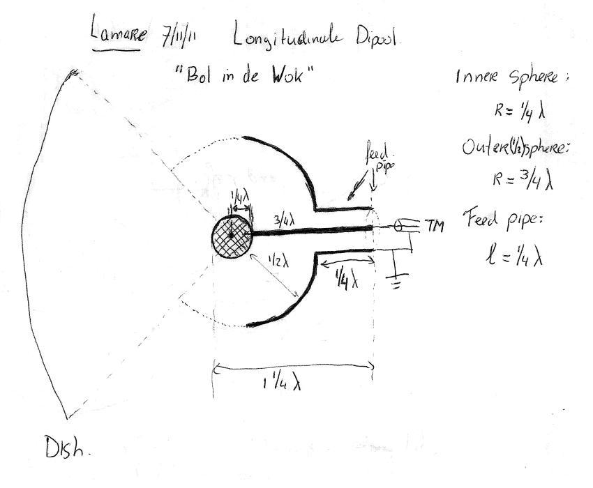
    Yesterday evening, I have been thinking about how to design a longitudinal antenna for use with a normal transmitter. The design used in the Swiss proof-of-concept was fed from the centre, but the coax mantle was floating, which is not such a good idea. This kept bothering me and after some deep thinking, I suddenly got an idea. The lamare longitudinal dipole:

    The idea is to make a whip antenna of 1 1/4 lambda, where at the tip of the whip we mount a sphere with a radius of 1/4 lambda. Concentric to that one, we mount a hollow sphere with a radius of 3/4 lambda.

    So, in between the spheres you have 1/2 lambda, so both are at a voltage node with a phase difference of 180 degrees.

    The outer sphere acts as a reflective shield. I have drawn this one as a half sphere, but of course you can match the opening in the outer sphere to the angle of your dish, and you get some gain as a result.

    Since a normal transmitter is designed to couple into a current node, we attach a feedpipe (or how do you call this?) of 1/4 lambda to the outer sphere, which is connected to ground at the feed point.

    The inner sphere is connected to the same feed point by means of a 3/4 lambda whip.

    The interesting thing is that because of the difference in propagation speed of a factor pi/2, your transversal resonance frequencies are also a factor pi/2 away from the frequency for which we design our longitudinal dipole, which causes a nice suppression of all the transversal junk we don't want in this case....


    @lamare

    nice concept and design.

    you will be able to fine tune it with the pipe I presume.

    2 questions....

    What kind of voltage do you predict on the node?

    and how do you plan to switch it from the transmission mode to receiver mode?

    Leave a comment:


  • lamare
    replied
    Originally posted by Kokomoj0 View Post
    in his work on the transmission of electricity, Dollard makes the distinction between dielectric and and magnetic induction but in this paper did not go to the elements of exactly how it works.

    Does anyone have any further information of the exact process that takes place that creates the pi/2 c condition?
    In essence, it's a matter of rotational movement of the ether in the case of the magnetic component versus straight movement in the case of the dielectric component.

    The magnetic component travels a netto path of half a circle, pi * r, while the dielectric component travels straight trough the centre of the circle, 2 * r. The division of these renders pi/2. In other words: the path the magnetic component has to travel is pi/2 times as long as the path the dielectric component has to travel. The magnetic component takes a detour, while the dielectric component does not....
    Last edited by lamare; 11-07-2011, 06:22 PM. Reason: typo

    Leave a comment:


  • Kokomoj0
    replied
    in his work on the transmission of electricity, Dollard makes the distinction between dielectric and and magnetic induction but in this paper did not go to the elements of exactly how it works.

    The electromagnetic theory, or what was known as the Hertzian wave theory in Tesla's era, fails to explain certain observations made in practical radio engineering. According to E.M. theory the propagating velocity of electric induction must be the velocity of light. In the practical world of engineering however, the factor π/2, or 1.57 times the velocity of light will appear in wave calculations. Is it not coincidental that Tesla claimed that the effective propagation velocity of his wireless system was π/2 faster than the so-called speed of light?

    Also, according to E.M. theory, the propagation of electric induction must be the cross combination of the dielectric induction and the magnetic induction, these two inductions never propagating independently. The work of J.J. Thomson and M. Faraday indicate that these two distinct forms of induction do propagate independently. Wheatstone claimed that the dielectric induction propagated at π/2 times faster than light.

    Does anyone have any further information of the exact process that takes place that creates the pi/2 c condition?

    Leave a comment:


  • lamare
    replied
    The lamare longitudinal dipole antenna (and/or dish feed)...

    Yesterday evening, I have been thinking about how to design a longitudinal antenna for use with a normal transmitter. The design used in the Swiss proof-of-concept was fed from the centre, but the coax mantle was floating, which is not such a good idea. This kept bothering me and after some deep thinking, I suddenly got an idea. The lamare longitudinal dipole:


    The idea is to make a whip antenna of 1 1/4 lambda, where at the tip of the whip we mount a sphere with a radius of 1/4 lambda. Concentric to that one, we mount a hollow sphere with a radius of 3/4 lambda.

    So, in between the spheres you have 1/2 lambda, so both are at a voltage node with a phase difference of 180 degrees.

    The outer sphere acts as a reflective shield. I have drawn this one as a half sphere, but of course you can match the opening in the outer sphere to the angle of your dish, and you get some gain as a result.

    Since a normal transmitter is designed to couple into a current node, we attach a feedpipe (or how do you call this?) of 1/4 lambda to the outer sphere, which is connected to ground at the feed point.

    The inner sphere is connected to the same feed point by means of a 3/4 lambda whip.

    The interesting thing is that because of the difference in propagation speed of a factor pi/2, your transversal resonance frequencies are also a factor pi/2 away from the frequency for which we design our longitudinal dipole, which causes a nice suppression of all the transversal junk we don't want in this case....

    Attached Files

    Leave a comment:


  • lamare
    replied
    Good news!

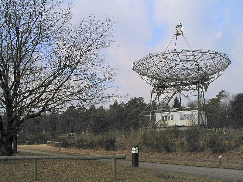
    If we manage to buld a proper transmitter, we can make use of this 25 meter dish for an experiment:
    Dwingeloo Radio Observatory - Wikipedia, the free encyclopedia


    The guy who responded to my mail is involved with the restoration of this dish and he said they could mount a feed at "their dish" and "aim a shot".

    WOW!
    Last edited by lamare; 10-31-2013, 07:52 PM. Reason: uptated url for image.

    Leave a comment:

Working...
X