Announcement

Collapse
No announcement yet.

Who performs the first longitudinal Moon-Bounce in history?

Collapse
X
 
  • Filter
  • Time
  • Show
Clear All
new posts

  • Kokomoj0
    replied
    Originally posted by lamare View Post
    Posted this on the jk_wireless Yahoo group:

    Yahoo! Groups


    I realize this gets a bit confusing. What should it be now, n * 1/2 lambda or n * 1/4 lambda??

    All right. Now the outside of your sphere is per definition a voltage node. You get these every 1/2 lambda.

    If you want to drive your sphere from a normal transmitter, which is designed to feed a normal dipole or 1/4 lambda antenna at a current node, you need to feed your sphere from the centre and it needs to have a radius of n * 1/4 lambda in order to get your current node at the centre in order to keep your transmitter happy.

    If you want to drive your sphere from a transmitter capable of driving a dipole at a voltage node (basically: high voltage, low current), you can either use a sphere with a radius of n * 1/4 lamda and drive it from the outside, or you can take a sphere with a radius of n * 1/2 lambda and drive it from the centre.

    At this moment it still has to be determined how to drive an antenna at a voltage node exactly.

    Eric Dollard's experiments suggests that capacitive coupling to a normal transmitter may work. A transmitter like Tesla's TMT probably also works very well, because it's coil is in a self-resonance mode and normally you use the already "open" side of the coil to drive your sphere. So, if you match the size of your sphere to the oscillation frequency of your TMT when oscillating without any capacitive load at the top, you're probably O.K.

    Its too bad Eric did not elaborate on that. He did say he was able to tune up with good swr into the ground in that conference video I believe.

    In this case wouldnt you simply impedance match your transmitter to operate into the primary with enough tuning capability to adjust for variations reflected from the tower to maintain a decent swr?

    I presume your amp would be electrically isolated and driving the primary coil into the ground no?

    Then in a pinch couldnt you adjust your voltage or current mode by a length of coax between the sphere and the top of the coil?

    Leave a comment:


  • Kokomoj0
    replied
    Originally posted by lamare View Post
    Jus try getting low frequency sounds, like a 100 Hz sine wave, from a loudspeaker designed for high frequencies (tweeter) or just any speaker with a very small cone and you know what I mean....

    For the moon-bounce project, we need high gain antenna's and considerable power, so we need to use sattellite dishes as antenna, fed with a sphere. Since readily available dishes have a diameter of in the order of 1 to may be 5m, I am aiming for high frequencies, at least 500 MHz or so.
    coils and design at that frequency get really hairy.

    Interestingly I am planning at some point in building a transmitter and that was the frequency of my first choice but am rethinking it due to the added complexities. For what you are trying to do I dont think you have that luxury. Lots of people still have those old 9ft sat dishes in their yards that might be a consideration.

    Leave a comment:


  • Kokomoj0
    replied
    @lamare

    doesnt the sphere become part of the whole system, which is to say, the best power transfer through the system that could be hoped for would be an exact impedance match between the coil capacitor and the environment at the system level operating frequency? It appears it would be dependent on the physical dimensions of the sphere as you talked about and all external factors, height, nearby objects etc etc? either way it would also need the transmitter to properly load up as well. I am having difficulty imagining how someone can get all these factors knowing what we know about wire mass, length, size etc into a best compromise situation as a system.

    If you wanted to feed the center what about putting a small solid core ball on the end of the coax center and insulator from the braid and the coax mounted so the ball is in the center of the sphere?

    Oddly enough my now 90 year old uncle used to put a small hollow ball over the tip of all his radio antenna's including these 900 mhz phones and to my surprize the reception was noticeably better!
    Last edited by Kokomoj0; 11-06-2011, 08:36 PM.

    Leave a comment:


  • Kokomoj0
    replied
    Originally posted by KurtNalty View Post
    I think the more convincing prospect for demonstrating superluminal
    longitudinal waves is to redo Wheatstone's demonstration.
    Yes that is a great idea, with todays equipment, as you said, so it reduces their ability as much as possible to speciously counter argue the matter, as there most likely will be interests that would prefer it is never known that will grab for any straw they can to derail the experiment.

    Leave a comment:


  • lamare
    replied
    Originally posted by broli View Post
    I'm not knowledgeable in that field.

    But what would the difference be between one large surface and many small individual patches covered over a large surface. The boundaries of these small patches do not connect but all are connected to the center of the sphere. Wouldn't that eliminate the standing wave issue on the sphere?
    As far as I can tell, there is no problem once you get a standing wave in your sphere. The idea of using a sphere with a normal transmitter comes from the paper I posted earlier:


    A spherical surface with a uniform periodic changing net charge q is equivalent to a pulsating point charge density.

    [...]

    The ball antenna source. –
    The geometry of the spherical antenna is indicated in fig. 1. A 433.59 MHz signal is fed into the inside of the metal sphere through a coaxial cable, where the outside grounded conductor acts as a shield. The result is an oscillating uniform spherical charge density that is the source of the radiating longitudinal electric E field. Mathematically a spherically symmetric source can generate only scalar waves; so the ball antenna can only generate a Φ-wave, and, thus, only a longitudinal electrodynamic E-wave. The spherically symmetric current density J within the ball, that gives rise to the pulsating surface charge source, is divergenceless, ∇ · J = 0; so ∇ · A = 0 and ∇ × A = 0; and no transverse wave can arise. The ball antenna as a receiver detects the net charge induced by the component of the incident E field normal to the front surface; so only longitudinal E-waves can be detected. An absorbing screen can be introduced to determine the direction of the incident longitudinal wave. Stray transverse fields generated by leads and neighboring objects play only a minor role.
    So, when you feed your sphere from the centre, no matter what, the waves always end up with the same phase at the outside. So, you can work with a small sphere when feeding from the centre without any standing wave problems. When fed from the centre, the problems are mostly related to how much power you can effectively radiate with such an antenna.

    When not fed from the centre, it depends on how small your sphere is compared to the wavelenghts used wether or not you get too much unwanted phase differences across the surface of your sphere. If it is small enough, you won't have a problem with that respect, but you won't be able to radiate much power either. And a small sphere fed from the center also won't radiate much power.

    Now normally an antenna is designed to resonate in order to get the largest possible radiation. So, I figured: the sphere must also resonate if you want to be able to transmit power effectively. And it turned out that the sphere the guys in the paper used had a radius of about 1/4 lambda.

    But feeding a sphere from the centre is very complicated. How do you fix a feedline to the centre of a shpere?

    Now when the sphere is designed to resonate at the frequency you desire, you will get a standing wave pattern such that the waves at the surface of your ball are always in phase because of the geometry of the sphere. And then and only then you can feed your sphere from the outside without any problem as far as I can tell, while still being able to radiate the optimum amount of power.

    So, from a practical point of view it is much easier to do it like that...
    Last edited by lamare; 11-06-2011, 06:37 PM. Reason: expanded quote

    Leave a comment:


  • KurtNalty
    replied
    Greetings,

    The problem with moonbounce is validating the actual path taken by
    the signal. You could imagine ionosphere reflections, intermediate
    ionized gas clouds, repeater satellites, Dark Knight repeaters, and
    plain old fraud invalidating the exercise.

    For what it is worth, AstroEngineer.wordpress.com claims that
    Mars rovers (Spirit, etc) are equipped with working superluminal
    transmitters. (Checkout the gnomon on the color calibrator
    as a candidate for the spherical transmitter.) His claim is that
    timestamped data at JPL documents pre-arrival of the data stream
    from the superluminal path, as compared to the conventional path.

    I think the more convincing prospect for demonstrating superluminal
    longitudinal waves is to redo Wheatstone's demonstration.

    Leave a comment:


  • broli
    replied
    I'm not knowledgeable in that field.

    But what would the difference be between one large surface and many small individual patches covered over a large surface. The boundaries of these small patches do not connect but all are connected to the center of the sphere. Wouldn't that eliminate the standing wave issue on the sphere?

    Leave a comment:


  • lamare
    replied
    Originally posted by broli View Post
    Also why are you worrying about standing waves on the surface of the sphere. What are the frequency ranges you had in mind? If the sphere is small and frequency has meter long wave lengths then it should be a none issue no? Even if you had a huge sphere and high frequency the standing waves on the surface would or should still emit longitudinal waves.
    Jus try getting low frequency sounds, like a 100 Hz sine wave, from a loudspeaker designed for high frequencies (tweeter) or just any speaker with a very small cone and you know what I mean....

    For the moon-bounce project, we need high gain antenna's and considerable power, so we need to use sattellite dishes as antenna, fed with a sphere. Since readily available dishes have a diameter of in the order of 1 to may be 5m, I am aiming for high frequencies, at least 500 MHz or so.
    Last edited by lamare; 11-05-2011, 10:55 PM.

    Leave a comment:


  • broli
    replied
    In that forum someone made an interesting remark, antennas we know radiate or at least should radiate a small, none existent according to maxwell equations, portion longitudinally. This alone is interesting to know and has been mentioned in distinti's "new electromagnetism theory".


    page 19
    I believe there's a more in depth derivation in some other pdf.

    Also why are you worrying about standing waves on the surface of the sphere. What are the frequency ranges you had in mind? If the sphere is small and frequency has meter long wave lengths then it should be a none issue no? Even if you had a huge sphere and high frequency the standing waves on the surface would or should still emit longitudinal waves. Just like a standard antenna emits transverse waves while its length is multiple times the length of the underlying wave.
    Last edited by broli; 11-05-2011, 10:49 PM.

    Leave a comment:


  • lamare
    replied
    Posted this on the jk_wireless Yahoo group:

    Yahoo! Groups

    I have been theorizing on how to build a system for the transmission of longitudinal waves, after I found this article wherein a succesfull practical proof of concept is described:


    Since it was reported by Dollard that the propagation speed of longitudinal waves is a factor pi/2 (1.57) larger than the propagation speed of transversal waves, I figured a demonstration of longitudinal moon bouncing would be THE final chapter for Einstein's relativity nonsense, so I started a thread at the EF to see how far we can come with that:


    Most important conclusion so far is that your sphere has to have an n * 1/4 lambda radius in order for it to resonate like a dipole antenna, since with a n * 1/4 lambda radius, you basically have an infinite array of 1/2 wave dipoles....

    Now if you want to calculate the wavelength for the frequency you are designing your transmitter for, you can simply calculate the corresponding transversal frequency by dividing your longitudinal frequency by pi/2 (1.57). I calculated that for the values reported in the paper:


    "They used a frequency of 433.59 MHz, with an equivalent EM frequency of 276 MHz. When we feed that in a wavelength calculator ( Frequency Wavelength Calculator ), we get a wavelength of about 1.1 m or 1/4 lambda of 27 cm, while they used a sphere with a radius of 30 mm, which would be about 10% more than 1/4 lambda."

    And apparantly that works pretty well. Interesting detail is that they feed their sphere from the centre, where you have a current node, just as what you have with a normal 1/4 lambda dipole, so you can drive it with a normal transmitter. (oops, that should have been: "a normal 1/2 lambda dipole" or "a normal 1/4 lambda wire antenna")

    If you drive it from the outside, you drive it at a voltage node, which means you drive it with high voltage, low current. Dollard used capacitive coupling in his longitudinal experiment, so that is probaly the way to go if you want to feed your sphere at a point at the outside. It may be a good idea to use a trimmer cap between your coil and your sphere, so you can tune the whole setup.

    I realize this gets a bit confusing. What should it be now, n * 1/2 lambda or n * 1/4 lambda??

    All right. Now the outside of your sphere is per definition a voltage node. You get these every 1/2 lambda.

    If you want to drive your sphere from a normal transmitter, which is designed to feed a normal dipole or 1/4 lambda antenna at a current node, you need to feed your sphere from the centre and it needs to have a radius of n * 1/4 lambda in order to get your current node at the centre in order to keep your transmitter happy.

    If you want to drive your sphere from a transmitter capable of driving a dipole at a voltage node (basically: high voltage, low current), you can either use a sphere with a radius of n * 1/4 lamda and drive it from the outside, or you can take a sphere with a radius of n * 1/2 lambda and drive it from the centre.

    At this moment it still has to be determined how to drive an antenna at a voltage node exactly.

    Eric Dollard's experiments suggests that capacitive coupling to a normal transmitter may work. A transmitter like Tesla's TMT probably also works very well, because it's coil is in a self-resonance mode and normally you use the already "open" side of the coil to drive your sphere. So, if you match the size of your sphere to the oscillation frequency of your TMT when oscillating without any capacitive load at the top, you're probably O.K.
    Last edited by lamare; 11-05-2011, 10:32 PM. Reason: oops

    Leave a comment:


  • lamare
    replied
    After a discussion on a Dutch radio amateur forum, which hopefully leads to contacts with some people that may actually be able to pull this off, I concluded that a sphere antenna actually needs to have a n * 1/2 lambda radius.

    The Dutch discussion is here:
    Zendamateur.COM - Toon onderwerp - Wie voert de eerste longitudinale moon-bounce uit??

    It may also be possible to use other shapes of antenna. The essential difference between transversal and longitudinal modes is this:

    a) a difference between propagation speed with a factor pi/2 regardless of the medium;
    b) "open" versus "closed" feedline.

    One end of the antenna, wether a sphere or a straight wire, is always open. That's where you per definition get a voltage node. At the feed point, you get either a voltage or a current node, depending on wether or not the feed point is able to "float" freely with regards to it's potential.

    Normally, the feed is connected to a more or less fixed potential, so you get a current node at your feed. Since Eric Dollard used capacitive coupling in his longitudinal demonstration, I concluded that you need to have a voltage node at your feed, which you can achieve by capacitively coupling your transmitter to the feed point.


    The interesting thing is that because of the factor pi/2 (1.57) the resonance frequencies of longitudinal vs. transversal modes are that different that your eventual configuration gets a clear preference for one of these modes at the desired frequency. In other words: you can suppress the transversal mode substantially with proper design.

    So, in order to make a longitudinal transmitter antenna, you need to make an n * 1/2 lambda antenna *and* you have to make sure that *both* ends of your antenna are "open" with respect to the applied potential, so hardly as little current as possible flows between your transmitter and your antenna, which results in the magnetic (transversal) components of your wave being supressed to a substantial degree.

    Leave a comment:


  • lamare
    replied
    Size of sphere

    I have been thinking a bit about how big the sphere should be. As with Herzian antenna, I think you would want a sphere with a 1/4 lambda radius.

    Given that the propagation speed of longitudinal waves is pi/2 times the propagation speed of a normal transversal wave trough the medium at hand, you would have to make the radius pi/2 times the quarter wave length as you would normally calculate for a 1/4 lambda antenna for EM operation.

    So, to calculate the ideal radius, you take the desired frequency and divide that by 1.57 (pi/2) to get the EM frequency with the same wave length. Then you can apply normal calculation.

    And if you're working with a 1/4 lambda sphere antenna, the size of the sphere is such that it matters how it is feeded. The feed should be at the centre.

    If you do not feed it at the centre, you would have to take a much smaller sphere, which would mean that you have to use much higher voltages to get the same amount of radiation. See for example:

    longitudinal waves

    Technology of Tesla require high potential source (up to millions Volts) that produce high frequency oscillations. Terminal that create the longitudinal wave is the spherical metal surface (sphere capacitor).
    And remember that Tesla worked in the kHz bands, which does not seem such a good idea to me if we want to aim for a succesfull moon-bounce while having to do without a power plant in our back yard....

    Also do not be fooled by the numerous pages about Tesla's Wireless Transmitter, like for example the kits and such sold by Prof. Meyl:
    ETZS-Shop - Hardware


    THIS IS NOT A SCALAR WAVE TRANSMITTER!!

    It is a small-scale replication of Tesla's Magnyfing Transmitter, which is NOT supposed to radiate at all!

    It is designed to PREVENT radiation!

    See my earlier post:

    Originally posted by lamare View Post
    <snip>
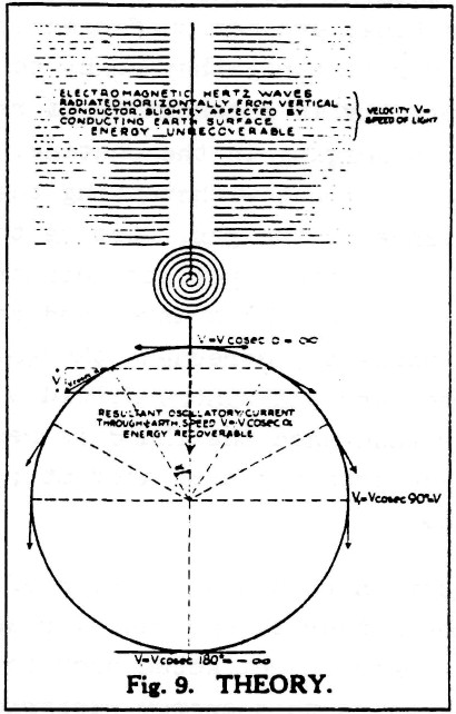
    Tesla illustrated this himself in an article "THE TRANSMISSION OF ELECTRICAL ENERGY WITHOUT WIRES" on March 5, 1904, which you can find at:
    Transmission of Electrical Energy Without Wires

    He used the following illustration to show the difference between electromagnetic radiation (either "Herzian" or longitudinal, btw) and his system:


    The text in the upper part of the picture reads:
    Electromagnetic Hertz waves radiated horiontally from vertical conductor, slightly affected by conducting Earth surface.
    ENERGY UNRECOVERABLE
    Now why is this so important? Because no matter what kind of waves are transmitted from the vertical conductor, with or without a sphere on top, the energy radiates away in all directions and is therefore lost for all but a very small fraction!

    This same picture is also printed in Eric Dollard's book, with the following comment:
    Tuks DrippingPedia : Theory Of Wireless Power

    It can therefore be seen that while the transmission of transverse waves involves the spraying of energy, with its consequent square law diminishment of energy density, and no hope of retrieving the unused energy, the Tesla system involves the direct connection of transmitter and receiver, via the pulsating lines of electric induction. Therefore, the transmitter and receiver are rendered as one apparatus.
    <snip>

    Now finally, back to your questions. First of all, yes, there are longitudinal waves being transmitted/exchanged between the transmitter and reciever balls. The point is that these radiate in all directions, no matter whether they are electromagnetic (Herzian) waves or Tesla's longitudinal waves. Both kind of waves diminish very rapidly when not quided such as to form a standing wave, because the energy is sprayed into space in both cases!!!!

    In Tesla's own words:
    Nikola Tesla On His Work With Alternating Currents -- Chapter IV
    I prefer to reduce those waves in quantity and pass a current into the earth, because electromagnetic wave energy is not recoverable while that [earth] current is entirely recoverable, being the energy stored in an elastic system.
    So, to sum this up:
    Yes, longitudinal waves as well as transversal waves are transmitted by your sphere/coil arangement. And yes, you can detect them at some distance and use them to transfer energy over a small distance. The point is that this kind of energy radiaton should be avoided as much as possible, because all energy radiated into space is wasted can cannot be recovered. And the energy gain that Tesla found, and which is why he called his invention the "Magnifying Transmitter", is to be found in the higher order resonance standing wave in/along the "ground" connection between transmitter and receiver.

    So, the critical component in a magnifying system is the "ground" connection between transmitter and receiver, which should be in higher order resonance and non-radiating. And that is the essential difference between the transmission of energy "trough the air" and Tesla's system.
    Btw, the term scalar wave is an oxymoron. Dollard:
    Tuks DrippingPedia : Energetic Form Posts

    I had a young student from Korea visit me a few years back. He had no problem understanding the basic concept of producing an energy synthesizing apparatus, because his mind was uncontaminated by all of the Bedini/Bearden falsehoods. The term Scalar Wave is an oxymoron, as scalar is part of the propagation constant that is NOT A WAVE! (Idiots!)

    [...]

    The disinformers have convinced you that this whole quantity (RB + XB) is scalar, RG is the only scalar component. It is DC and has NO FREQUENCY, no WAVELENGTH and thus NO WAVE!

    SCALER = NO WAVE

    GET IT???
    So, let's call the beast by it's proper name from now on: Longitudinal Dielectric Wave. No Magnetic component! No Scalar. It's a wave...

    So, now we know what we are talking about, it is clear that the actual transmission of HF longitudinal waves using low-voltages is basically unexplored territory. All the TMT replications currently out there are completely different beasts, because the spheres they are using are not designed as antenna.

    So, what we are facing is most of all the question of how to design our transmitter sphere antenna. It should have a radius of 1/4 lambda and should be fed from the centre of the sphere. With such a configuration, the antenna hopefully behaves pretty much like a normal 1/4 lambda antenna from the point of view of the transmitter. And that is important, because we need to have the proper impedance in order to get the energy from our transmitter into our antenna.

    Yes, you can use much smaller spheres and use the big hammer method with high voltages as Tesla did. If you want to do that: good luck.

    But if you want to get something working with a normal transmitter: go for a 1/4 lambda sphere.

    Now let's take a look at what Monstein and Wesley did:
    Monstein, Wesley - Observation of scalar longitudinal electrodynamic waves(2002).pdf

    They used a frequency of 433.59 MHz, with an equivalent EM frequency of 276 MHz. When we feed that in a wavelength calculator (Frequency Wavelength Calculator ), we get a wavelength of about 1.1 m or 1/4 lambda of 27 cm, while they used a sphere with a radius of 30 mm, which would be about 10% more than 1/4 lambda. And apparantly that works pretty well, including the way they feed it, which is at the centre indeed.

    How nice. The theory matches the practical implementation for a change.

    Last edited by lamare; 11-05-2011, 10:39 PM. Reason: typo, added link

    Leave a comment:


  • lamare
    replied
    NASA's Advanced Energetics for Aeronautical Applications: Volume II also has a piece on longitudinal waves, referring a.o. to Eric Dollard (BSRF):


    page 61:

    The BSRF researchers claimed that they have demonstrated that the wave propagation velocities of transverse waves and longitudinal waves are significantly different, even when they are produced by the same signal source.

    The wave velocity of transverse waves was determined by measuring the frequency for which low-power radio waves directly coupled to the end of a conductor of known length produced a resonance condition that resulted in a maximum voltage measured at the "far" (nonsource) end of the conductor. Wave velocity was calculated as (resonant) frequency times wave length, which was equal to frequency times conductor length times four. (The factor of four is included because reflected energy and input energy result in a maximum output when the conductor length is one-quarter of the full [electric] wave length.) The wave velocity of longitudinal waves was determined in a very similar manner; however, the radio waves were capacitively (i.e., not directly) coupled to one end of a conductor equal in length to the conductor used for the transverse wave velocity measurement. As was done for transverse waves, wave velocity was calculated as (resonant) frequency times conductor length times four.

    The results of these determinations were as follows:
    – transverse wave velocity = 2.44 x 10⁸ m/s = 0.81 x c; and
    – longitudinal wave velocity = 3.74 x 10⁸ m/s = 1.25 x c.

    The velocity of transverse waves in "free space" (i.e., not confined to a conductor or other physical material) has been measured to be 3.00 x 10⁸ m/s, and this value is commonly referred to as "the velocity of light, c" (Ref. 25).
    When we divide these velocities we get 1.25 / 0.81 = 1.54, very close to 1.57 (pi/2).

    In other words: these measurements by Eric Dollard a.o. confirm that with a conductor as a medium, in which the speed of light equals 0.81 x c, the longitudinal waves propagate a factor pi/2 faster than the transverse waves.

    Update:
    Fort those not so familiar with Eric Dollard's work, there are some video's available with his experiments. It appears NASA refers to these video's...

    At Vimeo:
    Tesla's Longitudinal Electricity - Eric Dollard, Peter Lindemann & Tom Brown
    Transverse & Longitudinal Electric Waves - Eric Dollard And Thomas Joseph Brown

    At YouTube:
    Eric Dollard Peter Lindemann Tesla's Longitudinal Electricity

    Eric Dollard Tesla Longitudinal wave Energy SBARC Ham Radio with Chris Carson
    (Partial) transcript of this one: Tuks DrippingPedia : Sbarc Lecture
    Last edited by lamare; 11-04-2011, 06:35 PM. Reason: Added vids

    Leave a comment:


  • broli
    replied
    I think the medium is indeed more important. You can easily send longitudinal electric waves, it happens all the time in wires and whatnot but experiments show those don't exceed the speed of light, in fact they slow it down. So the aether might show something different if you can manage to send a true longitudinal electric wave. Meyl also showed this. I'm also interested in the following question; Is this new speed a new limit then?
    Instantaneous transfer would be the ultimate goal and this has even been demonstrated with the concept of global scaling formulated by Hartmut Müller.
    Last edited by broli; 11-03-2011, 11:25 PM.

    Leave a comment:


  • lamare
    replied
    Finally found something of an answer in the right direction:

    Why do transverse waves travel faster than longitudinal waves? - Yahoo! Answers


    In solids, p-wave (longitudinal) speed is compressive strength [Oops! I mean modulus] divided by density of the medium; s-wave (transverse) speed is sheer strength [Oops! I mean modulus] divided by density. Transverse waves are always slower than longitudinal waves in the same medium because sheer strength is always less than compressive strength. Earthquake waves, for example: The p-waves are many times faster than the s-waves. [Modulus us like a spring constant; it's the ratio of stress to strain.]

    A gas has no sheer strength, so it does not provide a medium for transverse waves. So there are no transverse waves in air that can be compared to sound waves.
    And some formulas:
    Seimic Waves and Earth’s Interior

    P-waves are the first waves to arrive on a complete record of ground shaking because they travel the fastest (their name derives from this fact - P is an abbreviation for primary, first wave to arrive). They typically travel at speeds between ~1 and ~14 km/sec. The slower values corresponds to a P-wave traveling in water, the higher number represents the P-wave speed near the base of Earth's mantle.

    The velocity of a wave depends on the elastic properties and density of a material. If we let k represent the bulk modulus of a material, m the shear-modulus, and r the density, then the P-wave velocity, which we represent by a, is defined by:
    P Velocity


    A modulus is a measure of how easy or difficulty it is to deforms a material. For example, the bulk modulus is a measure of how a material changes volume when pressure is applied and is a characteristic of a material. For example, foam rubber has a lower bulk modulus than steel.

    P-waves are sound waves, it's just that in seismology we are interested in frequencies that are lower than humans' range of hearing (the speed of sound in air is about 0.3 km/sec). The vibration caused by P waves is a volume change, alternating from compression to expansion in the direction that the wave is traveling. P-waves travel through all types of media - solid, liquid, or gas.
    Secondary , or S waves, travel slower than P waves and are also called "shear" waves because they don't change the volume of the material through which they propagate, they shear it. S-waves are transverse waves because they vibrate the ground in a the direction "transverse", or perpendicular, to the direction that the wave is traveling.
    Tranverse Wave Motion

    As a transverse wave passes the ground perpendicular to the direction that the wave is propagating. S-waves are transverse waves.

    The S-wave speed, call it b, depends on the shear modulus and the density
    S-velocity


    Even though they are slower than P-waves, the S-waves move quickly. Typical S-wave propagation speeds are on the order of 1 to 8 km/sec. The lower value corresponds to the wave speed in loose, unconsolidated sediment, the higher value is near the base of Earth's mantle.

    An important distinguishing characteristic of an S-wave is its inability to propagate through a fluid or a gas because a fluids and gasses cannot transmit a shear stress and S-waves are waves that shear the material.
    Last edited by lamare; 11-03-2011, 11:03 PM.

    Leave a comment:

Working...
X