Announcement

Collapse
No announcement yet.

Who performs the first longitudinal Moon-Bounce in history?

Collapse
X
 
  • Filter
  • Time
  • Show
Clear All
new posts

  • lamare
    replied
    Someone mailed me this question:

    Since it cannot be shielded by metal or even dielectric material, why do you think you can feed a dish with a spherical termination and reflect it, concentrated, to the moon? Why do you think it will be reflected by the moon? Two big problems to my thinking.
    I believe the statement that longitudinal waves cannot be shielded is a myth, which appears to have originated by Meyl. He used two TMTs to transmit energy "into a Faraday cage", but a TMT transmits its power from transmitter to reciever by means of a wave guide, either the earth or a ground wire. So, the guiding "ground wire" nicely guides your "scalar wave" into the Faraday cage.

    Also see this post: http://www.energeticforum.com/renewa...tml#post165383

    Tesla also talked about unshieldable waves, but these were IMPULSES, not nice harmonic waves:

    Nikola Tesla - The Complete Patents of Nikola Tesla - The Man who invented the 20th Century
    "Broadcast Power" - Nikola Tesla

    Instantaneous applications of high current and high voltage could literally convert thin wires into vapor. Charged to high direct current potentials, his capacitors were allowed to discharge across a section of thin wire. Tesla configured his test apparatus to eliminate all possible current alternations. The application of a single switch contact would here produce a single, explosive electrical surge: a direct current impulse resembling lightning.

    [...]

    Placing a large glass plate between himself and the exploding wire, he performed the test again. Bang! The wire again turned to vapor...but the pressured stinging effect was still felt. But, what was this? How were these stinging effects able to penetrate the glass plate? Now he was not sure whether he was experiencing a pressure effect or an electrical one. The glass would have screened any mechanical shrapnel, but would not appreciably shield any electrical effects.

    Through careful isolation of each experimental component, Tesla gradually realized that he was observing a very rare electrical phenomenon. Each "bang" produced the same unexpected shock response in Tesla, while exploding small wire sections into vapor. The instantaneous burst produced strange effects never observed with alternating currents. The painful shocking sensation appeared each time he closed or opened the switch. These sudden shock currents were IMPULSES, not alternations. What surprised him was the fact that these needle-like shocks were able to reach him from a distance: he was standing almost ten feet from the discharge site!

    [...]

    The secret lay principally in the direct current application in a small time interval. Tesla studied this time increment, believing that it might be possible to eliminate the pain field by shortening the length of time during which the switch contact is made. In a daring series of experiments, he developed rapid mechanical rotary switches, which handled very high direct voltage potentials. Each contact lasted an average of one ten-thousandth second.

    Exposing himself to such impulses of very low power, he discovered to his joy and amazement that the pain field was nearly absent. In its place was a strange pressure effect, which could be felt right through the copper barriers. Increasing the power levels of this device produced no pain increase, but did produce an intriguing increased pressure field. The result of simple interrupted high voltage DC, the phenomenon was never before reported except by witnesses of close lightning strokes. This was erroneously attributed however to pressure effects in air.

    [...]

    Analysis of this situation proved that electrical energy or electrically productive energies were being projected from the impulse device as rays, not waves. Tesla was amazed to find these rays absolutely longitudinal in their action through space, describing them in a patent as "light-like rays". These observations conformed with theoretical expectations described in 1854 by Kelvin.

    In another article Tesla calls them "dark-rays", and "rays which are more light-like in character". The rays neither diminished with the inverse square of the distance nor the inverse of the distance from their source. They seemed to stretch out in a progressive shock-shell to great distances without any apparent loss.
    Eric also makes clear distinction between 4 types of waves in his "Symbolic Representation of the Generalized Electric Wave", one of them being "impulses". ( http://www.tuks.nl/pdf/Eric_Dollard_...%20Dollard.pdf)

    Tesla also wrote a lot about various "rays", which appear to connect to these impulses and to electric phenomena as well:

    Nikola Tesla : Nikola Tesla Plans to Keep "Wireless Thumb" on Ships at Sea

    As far back as 1897, I disclosed before the New York Academy of Sciences the discovery that Roentgen, or X-rays, projected from certain bulbs have the property of strongly charging an electrical condenser at a distance.
    Googling for "rays site:rastko.rs" gives more info on this, like:

    Nikola Tesla : Radio Power Will Revolutionize the World

    I have disintegrated atoms in my experiments with a high potential vacuum tube I brought out in 1896 which I consider one of my best inventions. I have operated it with pressures ranging from 4.000.000 to 18.000.000 volts. More recently I have designed an apparatus for 50.000.000 volts which should produce many results of great scientific importance.

    But as to atomic energy, my experimental observations have shown that the process of disintegration is not accomtpained by a liberation of such energy as might be expected from the present theories.

    And as for the cosmic ray: I called attention to this radiation while investigating Roentgen rays and radioactivity. In 1899 I erected a broadcasting plant at Colorado Springs, the first and only wireless plant in existence at that time, and there confirmed my theory by actual observation, My findings are in disagreement with the theories more recently advanced.

    I have satisfied myself that the rays are not generated by the formation of new matter in space, a process which would be like water running up hill. According to my observations, they come from all the suns of the universe and in such abundance that the part contributed by our own sun is very insignificant by percentage. Some of these rays are of such terrific power that they can traverse through thousands of miles of solid matter.
    Be aware that when you read Tesla's work on rays, etc. that his discoveries and understanding grew over time. So, material from say 1890 may contain different statements than material from say 1930.

    Anyway, it seems to me that "ray" phenomenon are related to "impulses" and "particles", which can penetrate "transparant" material, depending on the size of the particles. But normal harmonic "alternating" waves behave very much like sound waves.

    And this is also what Eric suggested when talking to Dave:

    Yahoo! Groups

    Eric suggested more authors to study. He said look up the work of Helmholtz, "Sensations of Tone" (This seems to give insight into Eric's understanding of the music/electric relation) and that Helmholtz gave the equations for longitudinal transmission. Also Tesla liked Helmholtz. He also said to study everything by J.J. Thomson, especially "Experimental Researches into Electricity and Magnetism" (The only thing that I could find was "Elements of the mathematical theory of electricity and magnetism", maybe this is what he meant?).
    Last edited by lamare; 11-25-2011, 04:12 PM.

    Leave a comment:


  • lamare
    replied
    New antenna design: the longitudinal "cantenna"

    Yesterday, I studied some information on wave guides and I found out that the transverse wave propagation modes trough a hollow tube are only possible with a minimum diameter of 0.59 λ:


    In order for the waves to travel with low loss, the pipe dimensions must be large enough for the lowest-order waveguide mode, the TE 11 mode, to propagate. In circular waveguide, the cutoff wavelength for this mode is 1.706×D (diameter) so the minimum waveguide diameter is 1/1.706, or 0.59 λ. The diameter of the copper water pipe I used is nominally 3/ 4-inch, type M, which has a larger inner diameter than other types. The typical inner diameter is 0.81 inches, but that may vary slightly because this is not precision tubing. Thus, the cutoff wavelength is 1.38 inches, so the minimum frequency is 8.55 GHz. Clearly, 10 GHz is comfortably above the minimum.

    Moving in the other direction, a large waveguide diameter would permit additional higher-order waveguide modes to propagate. While the additional modes also propagate with low loss, they often arrive at the far end with different phase, so that they interfere with the TE11 wave and we are unable to extract them without losses. The next mode, TM 01, needs a minimum diameter of 0.76 λ to propagate, setting the maximum operating frequency without any additional modes. For the 3/4-inch pipe, this upper frequency limit is 11.08 GHz, but it isn’t a hard limit like the lower cut-off frequency.
    On the same site, you can find an interesting "Online Microwave Antenna Book": Table of Contents - W1GHZ Microwave Antenna Book ONLINE

    This chapter describes the so-called "coffee-can" or "cantenna" feeds:


    These are very simple to make:
    How to build a tin can waveguide antenna
    Wlan waveguide antenni


    And are ideal for feeding satellite dishes:
    Use a Surplus Primestar Dish as an IEEE 802.11 Wireless Networking Antenna

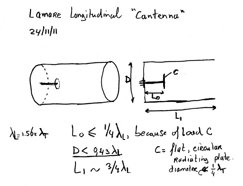
    Being an expert on longitudinal acoustic resonance ( http://www.tuks.nl/img/Arend_ossenhoorn_klein.jpg ), I figured that it must be possible to make the same kind of cantenna for longitudinal use.

    After some thinking, I came up with this:


    (High res version here: http://www.tuks.nl/img/Lamare_Longit...ntenna_big.jpg )

    The idea is to place a 1/4 λ whip antenna at the bottom of the can, and load that with a circular disc, which would be a flat radiator, comparable to the conus of a speaker. The disc adds some extra "length" to the whip, so the whip will will have to be shorter than actually 1/4 λ. A first guess may be something like 1/4 λ minus the radius of the disc radiator. However, the disc also adds a capacitative load to the 1/4 λ resonator, so the whip will have to be a bit more shortened. How much will have to be experimentally established.

    The length of the tube should be a little less than 3/4 λ, just as with an open cylindrical acoustic tube, which is very comparable to the longitudinal dielectric antenna we are talking about:

    Acoustic resonance - Wikipedia, the free encyclopedia
    Open cylindrical tubes resonate at the approximate frequencies
    where n is a positive integer (1, 2, 3...) representing the resonance node, L is the length of the tube and v is the speed of sound in air (which is approximately 343 meters per second at 20 °C and at sea level).
    All right, that was the easy part. Now how big should the diameter of the tube be?

    As I wrote above, the minimal diameter for transverse use is about 0.59 λ. And since we don't want any transversal junk in our longitudinal antenna, it is clear that this limit is our maximum diameter! However, this is expressed in terms of the transverse wavelength, so in terms of longitudinal wavelenghts the diameter of the tube should be maximal 0.59/1.56 = 0.38 λ (note that in the drawing I took the "popular" 0.67/1.56 = 0.43 λ as maximum, which should be 0.59 λ transverse). For 1296 Mhz, this works out to a maximum diameter of about 12.5 cm.

    Now the diameter of the disc. A hard upper limit for that one is 1/4 λ transverse, because the last thing we want is our disc to radiate transversal junk from a resonating radiator. So, the diameter of the disc should be signficantly smaller than 5.4 cm on 1296 Mhz.

    If we assume the radius of the disc, together with the length of the whip, should be about 1/4 λ longitudinal, a radius of about 1/4 * 1/4 = 1/16 λ longitudinal may be a good first guess, which works out to a radius of about 2.1 cm (or a diameter of 4.2 cm, of course). A coin, like 5 Euro cents, may be perfect for this kind of duty...

    Update: Further ideas for optimizing this design can be found in the theories about acoustic wave guides, like for example:
    Practical DIY Waveguides - Part 1
    Last edited by lamare; 11-24-2011, 10:07 PM.

    Leave a comment:


  • OrionLightShip
    replied
    Lamare, you and Raui make available a large collection of reference material and it is very much appreciated!

    Leave a comment:


  • lamare
    replied
    I made a new version of my spreadsheet:


    Also received some info from Eric trough the yahoo group:
    Eric suggested more authors to study. He said look up the work of Helmholtz, "Sensations of Tone" (This seems to give insight into Eric's understanding of the music/electric relation) and that Helmholtz gave the equations for longitudinal transmission. Also Tesla liked Helmholtz. He also said to study everything by J.J. Thomson, especially "Experimental Researches into Electricity and Magnetism" (The only thing that I could find was "Elements of the mathematical theory of electricity and magnetism", maybe this is what he meant?).
    I added Helmholtz' book to my list of references:
    Tuks DrippingPedia : Links And References

    The formula for describing a Helmholtz resonator, which is of course what my sphere with wip can be considered to be, can be found at WikiPedia:
    Helmholtz resonance - Wikipedia, the free encyclopedia


    Or, in plain text: f_h = v/(2*pi) * sqrt ( A/(V_0 * L) )

    With:
    v - propagation speed
    A - the cross-sectional area of the neck
    V_0 - the static volume of the cavity
    L - the length of the neck

    There is also an interesting article on Helmholtz acoustic resonators here:

    Helmholtz Resonant Absorber — Reviews and News from Audioholics


    The Helmholtz resonator is a narrow-bandwidth device, designed and used to target specific single frequency anomalies. The margin for design or constructional error, therefore, is minimal. One area often overlooked is that of port end-correction, without which a design may be rendered ineffective. Basically speaking, the air immediately outside either end of the port acts in sympathy with the design air mass in the port. This has the effect of increasing the apparent length of the port (fig1), and hence affects the tuning frequency of the resonator.
    The spreadsheet link in the article is dead, but I managed to grap a copy from archive.org:


    So, a Helmholtz resonator has a narrow bandwidth, but it can be tuned by varying the length of "the neck"...


    So, next thing I will do is to add these formulas to my spreadsheet and see where that gets me. As far as I can tell now, the neck should be considered to be the part of the whip without the balun, because we are working with a closed pipe (the balun part) and the Helmholtz equations assume an open pipe...


    Also see:
    Engineering Acoustics/Noise control with self-tuning Helmholtz resonators - Wikibooks, open books for an open world

    woofertester.com
    Last edited by lamare; 11-23-2011, 11:45 AM.

    Leave a comment:


  • lamare
    replied
    Longitudinal speed is NOT pi/2 times c....

    As I posted, I found out that the transverse surface wave across the sphere can be expressed with the theoretical formula for Schumann resonance:

    Schumann resonances - Wikipedia, the free encyclopedia

    f_n= c/(2*pi*r) * sqrt(n(n+1))
    I calculated the diameter for a 1/2 lambda sphere using Dollard's formula that the speed of longitudinal waves is pi/2 times c, but then the corresponding Schumann resonance frequency turned out to be 1287 MHz, which should be 1296 MHz if Eric's formula is correct.

    So, I compared the Schumann formula with the formula for resonance in a string, basically a 1/2 lambda resonance with closed ends:

    f_n = (n * c_l)/ 2L
    Since L = 2r, we can now calculate the theoretical speed c_l. When we take n=1 in the string formula and n=2 in the Schumann formula, we end up with matching resonance frequencies.

    Since n(n +1) equals 6 for n=2, we get:

    c_l / (4 * r) = c_t / (2 * pi * r) * sqrt(6)
    This works out to:

    c_l = 2/pi * sqrt(6) * c_t
    This computes to 1,559393604, while pi/2 computes to 1,570796325, a difference of 0,7%.....

    So, now we have a theoretical derivation for the longitudinal wave speed, which turns out to be just a tiny bit lower than Eric's pi/2...
    Last edited by lamare; 11-23-2011, 11:41 AM.

    Leave a comment:


  • Kokomoj0
    replied
    Originally posted by lamare View Post
    So, we get the situation that our transversal component has a resonance across the circumference of the sphere. while the longitudinal component resonates perpendicular with respect to the surface of the sphere.

    However, since we feed the sphere from a point at the surface, you have just as much waves going "left" as waves going "right", so with a sphere the transverse (magnetic) components nicely cancel each other out at all times, regardless of resonance or not. (Is this true??)

    Anyway, with the big "wok" sphere we have to choose our question mark such that we establish the same thing, transverse resonance as well, OR we choose to supress the transverse component over there.

    I'm still puzzling about whether or not the transverse component is effectively canceled out in such a (partial) sphere arrangement. Yes, you have waves going in opposite directions, but they are also at a certain distance in space with respect to one another.

    Something to think about further.
    I think that you will still get TW's at some harmonic because you are technically feeding a coil (well sorta.....due to skin effect) between the balun and the sphere.

    I am thinking that the only way you can avoid that is to center feed the sphere and terminate your transmission line centrally or directly on the surface of the sphere? By that I am thinking terminate your (transmission line) balun on the surface of sphere?

    I believe your objective is to have anything that comes out of the transmitter to exit strictly by means of the sphere.

    .
    Last edited by Kokomoj0; 11-22-2011, 03:41 AM.

    Leave a comment:


  • lamare
    replied
    Back to the drawing board. Again.....

    I finally found some formula that describe surface resonances occuring on an ideal sphere. We all know them. Schumann resonances:
    Schumann resonances - Wikipedia, the free encyclopedia

    Basic theory

    Lightning discharges are considered to be the primary natural source of Schumann resonance excitation; lightning channels behave like huge antennas that radiate electromagnetic energy at frequencies below about 100 kHz.[20] These signals are very weak at large distances from the lightning source, but the Earth–ionosphere waveguide behaves like a resonator at ELF frequencies and amplifies the spectral signals from lightning at the resonance frequencies.[20]

    In an ideal cavity, the resonant frequency of the n-th mode fn is determined by the Earth radius a and the speed of light c.[11]

    f_n= c/(2*pi*a) * sqrt(n(n+1))

    The real Earth–ionosphere waveguide is not a perfect electromagnetic resonant cavity. Losses due to finite ionosphere electrical conductivity lower the propagation speed of electromagnetic signals in the cavity, resulting in a resonance frequency that is lower than would be expected in an ideal case, and the observed peaks are wide. In addition, there are a number of horizontal asymmetries – day-night difference in the height of the ionosphere, latitudinal changes in the Earth magnetic field, sudden ionospheric disturbances, polar cap absorption, etc. that produce other effects in the Schumann resonance power spectra.
    So, I entered this formula in my spreadsheet:


    Turns out that when I calculate with a velocity factor of 0,91, the formula for the small sphere *exactly* matches the Schuman resonance mode 2 for a frequency of 1286 MHz (which rolls out independent of the chosen velocity factor because the radius of the small sphere depends on the velocity factor, btw), while I am designing the antenna for 1296 MHz.

    I also found some further references on Schumann resonance:


    So, it looks like we need to account for this Schumann resonance effect, one way or the other...

    Some quick investigation suggests we may have to double the radius of the small sphere in order to avoid transverse Schuman resonance.
    Last edited by lamare; 11-21-2011, 09:00 PM.

    Leave a comment:


  • lamare
    replied
    Design v4 and v5....

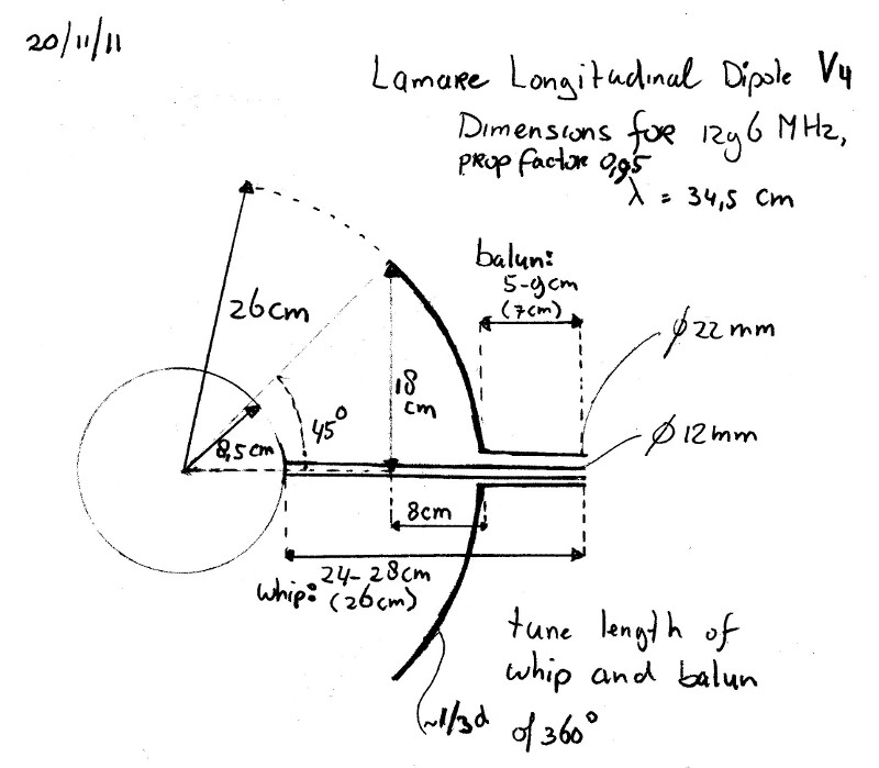
    Based on the last update in the above post explaining we can choose any odd multiple of 1/15th of the circumference of the big sphere, we can also opt for 5/15th, which would be 1/3d.

    Therefore version 4 of the design:


    Grrrrr.

    How much is 360 divided by 3??

    Right, 120...


    Yep, that's another number than 90....

    So, back to the drawing board....


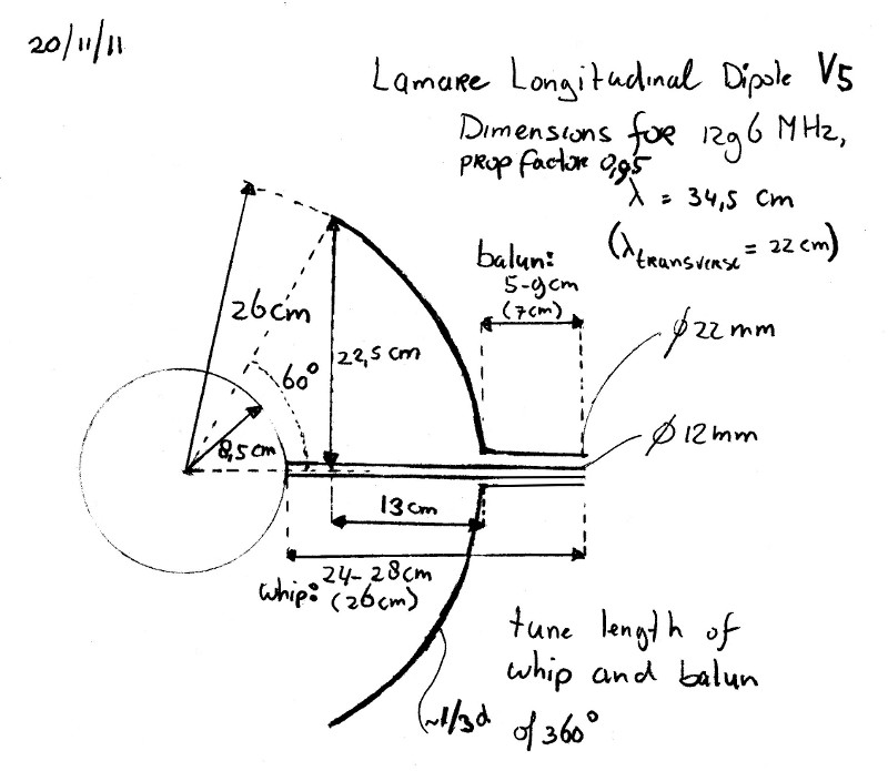
    Update: Here's version 5:


    With a high-res version for printing, etc:


    Update 2:

    I have done some calculations on the surface area of these so called "spherical caps", which you can find in my spreadsheet:


    It turns out that a cap for 1/5th has a surface area of about 86% of the surface of the small sphere, while a 1/3 cap will give avout 225% of the surface of the small sphere.

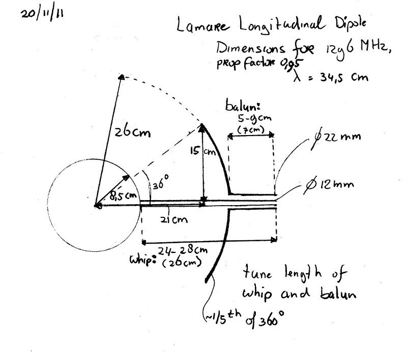
    So, I think we'll go for version 3. Easier to make, and more in balance with respect to surface area's (== self capacitance and/or charge density):

    High res version:


    And that's it for today...
    Last edited by lamare; 11-20-2011, 09:49 PM.

    Leave a comment:


  • lamare
    replied
    New design

    Based on the above posts, we now have a new design, version 3:


    High res version: http://www.tuks.nl/img/Lamare_Longit...ole_v3_big.jpg
    Last edited by lamare; 11-20-2011, 09:34 PM.

    Leave a comment:


  • lamare
    replied
    Man, is this hard to get straight!

    Longitudinal waves have a higher propagation speed and therefore a longer wavelength than transverse waves.

    So, in a given length or circumference, more transversal wavelengths fit in the same distance compared to longitudinal wavelengths.

    Therefore, my calculation should have been:

    The small sphere has a radius of 1/4 lambda longitudinal, which means it has a circumference of 2 * pi times 1/4 lambda longitudinal. Since transverse waves travel at a speed pi/2 times as slow, we have to multiply by pi/2 to get the circumference in terms of the corresponding transverse wavelength, which gives us: ( 2 * pi * 1/4 lambda) * (pi/2) = pi^2 * 1/4 lambda = 2,4674 or just about 2 1/2 lambda....

    All right, so the circumference of the outer sphere is very close to 2 1/2 lambda transversal, so it is very close to a transverse resonance frequency, but there's a phase difference of 180 degrees between the transmitted and returned wave, so we do get an almost canceling out of the transverse waves after all....

    And since we have 5/2 lambda in a whole circle/sphere, we should take 1,2,3,4 or 5 fifth of a whole sphere for our outer sphere to get a cancelling-out transverse resonance.

    Right?

    Update:

    Compare this to the resonant circular loop antenna:
    Loop antenna - Wikipedia, the free encyclopedia

    The large or self-resonant loop antenna can be seen as a folded dipole which has been reformed into a circle (or square, etc.). This loop has a circumference approximately equal to one wavelength (however it will also be resonant at odd multiples of a wavelength). Compared to the dipole or folded dipole, it transmits less toward the sky or ground, giving it a somewhat higher gain (about 10% higher) in the horizontal direction.

    Contrary to the small loop antenna, this design radiates in the direction normal to the plane of the loop (thus in two opposite directions). Therefore these loops are normally installed with the plane of the loop in the vertical direction, and may be rotatable. Further directionality can be obtained by using a loop whose circumference is not one but 3 or 5 wavelengths.
    So, when we take multiples of a whole wavelength, we get a transversal resonance mode that does not cancel out, while if we take odd multiples of a halve wave, we get a transversal resonance mode that does cancel out.

    Since 1/5 of the total circumference equals 1/2 lambda in transverse mode, we should take 1, 3 or 5/5th for our outer sphere in order to suppress the transversal junk we don't want...

    Update 2:

    As I said, it is hard to get this all straigt out.

    Since the circumference of the small sphere is about 5/2 lambda and the outer sphere is 3 times as big, we get 3 times 2 1/2 = 7 1/2 or 15/2 lambda across the circumference of the large sphere.

    So, one fifteenth of the big sphere equals 1/2 transverse lambda. Fortunately, three times this number, 3/15th or 1/5th, gets us 1 1/2 lambda, which is what I calculated with....

    So, we have some more choices for our outer sphere, but 1/5th should be fine.
    Last edited by lamare; 11-20-2011, 09:39 PM.

    Leave a comment:


  • lamare
    replied
    Filling in the ? mark...

    First, let's get back the picture of my design:


    So far, I regarded the question mark as "don't care". Oops.

    Let's first take a look at the small sphere. It has a radius of 1/4 lambda longitudinal, which means it has a circumference of 2 * pi times 1/4 lambda longitudinal. Since transverse waves travel at a speed pi/2 times as slow, we have to divide by pi/2 to get the circumference in terms of the corresponding transverse wave, which gives us: ( 2 * pi * 1/4 lambda) / (pi/2) = (2 * 1/4)/(1/2) lambda = 1 lambda.

    Oops. I first made a little calculation error. The circumference of a circle is 2 * pi * r, not pi * r.

    So, we get the situation that our transversal component has a resonance across the circumference of the sphere. while the longitudinal component resonates perpendicular with respect to the surface of the sphere.

    However, since we feed the sphere from a point at the surface, you have just as much waves going "left" as waves going "right", so with a sphere the transverse (magnetic) components nicely cancel each other out at all times, regardless of resonance or not. (Is this true??)

    Anyway, with the big "wok" sphere we have to choose our question mark such that we establish the same thing, transverse resonance as well, OR we choose to supress the transverse component over there.

    Since in that case we don't have a closed circle, but an open end, we have to account for that. As our antenna behaves as an open cylinder, because it is fed from a voltage node in our feed-line, we get (voltage) resonances at every odd multiple of 1/2 lambda:

    Acoustic resonance - Wikipedia, the free encyclopedia
    Open cylindrical tubes resonate at the approximate frequencies

    f = (nv / 2L)

    where n is a positive integer (1, 2, 3...)

    Now with a half-sphere fed from a the central point as shown in the picture, you basically have an infinite array of (multiples of) half-wave antenna's arranged in a circle. So, in a "bowl" shaped partial half-sphere, you get an infinite set of half wave "antenna's" arranged in a circle.

    Because we feed our half wave antenna from a voltage node in our feed line (basically high voltage, low current), we get our current hot spots about at 1/4 lamda away from our feed point, so we get a circular current "hot spot".

    Since the outer sphere has a circumference of 3 lambda, we can take either 1/3 or 2/3ds and we get it in the same kind of resonance mode as our inner sphere.

    I'm still puzzling about whether or not the transverse component is effectively canceled out in such a (partial) sphere arrangement. Yes, you have waves going in opposite directions, but they are also at a certain distance in space with respect to one another.

    Something to think about further.
    Last edited by lamare; 11-20-2011, 01:52 PM. Reason: Basically a total overhaul...

    Leave a comment:


  • lamare
    replied
    Originally posted by Web000x View Post
    Lamare,

    I just got off of the phone with Eric. I asked him about your proposal for using a dish structure for propagating a longitudinal wave towards the moon. He told me that longitudinal waves generally don't need the structure of a dish to begin to propagate. He said that you could possibly use such a structure but would need to see the schematics of the setup to help direct you. If you want to compile a schematic and send it to his Lone Pine address, he would be more than willing to direct you.

    Dave
    Already mailed him the contents of this thread last thursday. Shoule be in LP within 4-9 working days, which would be between the 16th and 23d of november...

    Would be nice if I could get a reply before november 26th if I want to keep my schedule aiming for december 21st, the shortest day of the year for publicity reasons. So, hopefully it arrives nicely at the 16th...
    Last edited by lamare; 11-12-2011, 10:55 PM.

    Leave a comment:


  • Web000x
    replied
    Lamare,

    I just got off of the phone with Eric. I asked him about your proposal for using a dish structure for propagating a longitudinal wave towards the moon. He told me that longitudinal waves generally don't need the structure of a dish to begin to propagate. He said that you could possibly use such a structure but would need to see the schematics of the setup to help direct you. If you want to compile a schematic and send it to his Lone Pine address, he would be more than willing to direct you.

    Dave

    Leave a comment:


  • lamare
    replied
    New drawing of dipole

    Hi all,

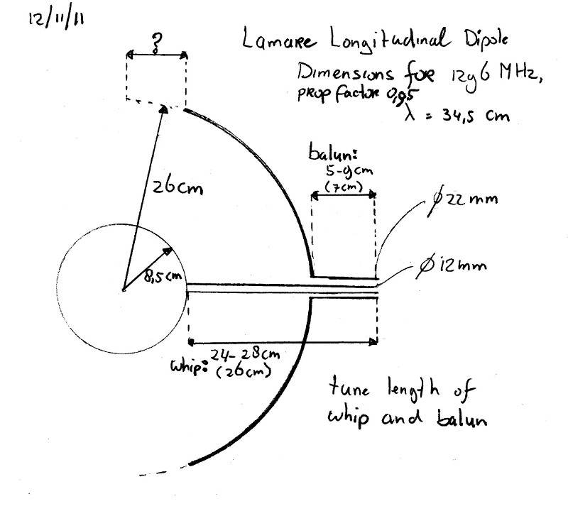
    I made a new drawing of the lamare longitudinal dipole antenna, with dimensions for 1296 MHz:


    Updated spreadsheet with my calculations:


    Oh yeah, I almost forgot. Aluminum and copper can be soldered together:

    solder-aluminium
    Aluminium antenna designs are often limited by the difficulty of performing a metal joining operation where the RF impedance is low, for example at the centre junction of groundplane antenna or at the centre of a dipole element. There then follows the very real difficulty in terminating the copper coaxial conductors onto an aluminium driven element. Those with experience know too well the corrosive effect of two dissimilar metals exposed to weather. The feed point impedance of a driven element in a multi element yagi array is of the order of five ohms or less and I suspect that many of my failed antennas were merely defective only at this feedpoint.

    For RF conductivity, the only true options are all copper elements permitting well soldered , low impedance joints; at the cost of heavy weight and monetary cost. My most successfull yagi antennas all had copper driven elements. If only it were possible to make a true metalurgical bond to aluminium at moderate temperature that would be compatible with copper.

    It is possible, sometimes, and with exotic alloy solders and exotic fluxes. Aluminium soldering is nothing new, however, manufactures keep their methods to themselves and makers of the solders will not release usage notes. Here I present a highly reproducible method that a competent Radio Ham can replicate using only a simple and inexpensive propane gas torch.


    The method requires the use of a now commonly sold aluminium brazing rod. This rod is made under the trade name Alumalloy and sold in the United States under the name Durafix. It , I believe, is a ternary alloy made from aluminium, copper and magnesium with a melting point of 430 degrees C. It has been available under various trade names in Australia for a number of years, it is known here in Oz as " aluminium rubbing solder". There is absolutely no application information published about it. (conspiracy theories welcomed here!) I have recently learned how to apply this remarkable alloy to make aluminium to aluminium brazed joints, after watching some Youtube videos. Search Youtube for the term "Alumalloy" and see for yourself. I have used it with success to make some antenna elements with it. Only the next step remained....bonding copper conductors to my aluminium antenna elements.

    [...]

    The technique.

    The Alumalloy braze melts at about 430 degress C, pure Al and its common alloys at about 700 degress. 400 degrees is well within the power of a propane torch, but utterly beyond the upper range of a soldering iron.

    Heat the base metal from below. Touch the brazing rod to the base metal. Do not heat the brazing rod directly with the torch...it will just melt and oxidise.
    When the metal is at the right temperature the braze will begin to melt. As it melts rub the base metal with the rod. This breaches the oxide monolayer and permits an instant metal-metal bond to form under the molten surface. The Oxide monolayer is unstable on the brazed surface and liquid braze will literally burrow underneath it. Rub the molten braze bead with a stainless steel knife and "tin" the surface of the base metal. The purpose of rubbing with the steel blade is to breach large areas of the oxide layer under the braze melt. Continous heating is required while you are doing this. The initial bead of molten braze will not wet the Alumium surface untill that surface is scratched UNDER the bead. The molten bead temporarily excludes atmospheric oxygen and only then will it bond with the base metal.

    Wipe the layer of oxidised dross with the knife blade away from the brazed surface and allow to cool. Reheat from below. Apply conventional 60/40 lead-tin resin fluxed solder to the brazed surface and do not overheat or permit the resin flux to burn. A perfectly formed solder bead will form ! Allow a large bead to form on the surface and cool. Your copper conducter can now be reflow soldered to this surface. At this point a very heavy 100W iron may have enough power , gas is better because of the very high thermal conductivity of Aluminum metal. A perfect copper to aluminum solder bond is thus made.

    The base metal should be prepared by filing to bare metal with a very fine bastard file to produce the smoothest surface possible. Polish with a FINE wire brush, a suede fabric brush is what is really needed here. If the surface has been anodised, this must be completely abraded away to bare metal.
    Last edited by lamare; 11-12-2011, 10:42 PM. Reason: Added aluminum solder info

    Leave a comment:


  • lamare
    replied
    Originally posted by Kokomoj0 View Post
    ok someone posted this I do not remember who, but I do not see that they have or claimed to have established a ground connection between Tx and Rx, which according to tesla is where the 292mps speed


    Europhys. Lett., 59 (4), pp. 514–520 (2002)

    EUROPHYSICS LETTERS 15 August 2002

    Observation of scalar longitudinal electrodynamic waves
    C. Monstein1 and J. P. Wesley2
    1 ETHZ, Institute of Astronomy - Scheuchzerstrasse 7, CH-8092 Z¨urich, Switzerland
    2 Weiherdammstrasse 24, D-78176 Blumberg, Germany
    (received 18 February 2002; accepted in final form 14 May 2002)
    PACS. 41.20.-q – Applied classical electromagnetism.
    PACS. 41.20.Jb – Electromagnetic wave propagation; radiowave propagation.


    If they do not have the units correctly grounded for their tests then I dont see this test as valid in as much as non-em longitudinal as tesla claimed.

    I posted that article in my very first post in this thread:

    Originally posted by lamare View Post
    So, I went looking for some information on how to do this in practice, and it seems that all you need to be able to transmit and/or recieve longitudinal waves is spherical antenna:

    Monstein, Wesley - Observation of scalar longitudinal electrodynamic waves(2002).pdf

    Mathematically a spherically symmetric source can generate only scalar waves; so the ball antenna can only generate a Φ-wave, and, thus, only a longitudinal electrodynamic E -wave. The spherically symmetric current density J within the ball, that gives rise to the pulsating surface charge source, is divergenceless, ∇ · J = 0; so ∇ · A = 0 and ∇× A = 0; and no transverse wave can arise. The ball antenna as a receiver detects the net charge induced by the component of the incident E field normal to the front surface; so only longitudinal E-waves can be detected.
    This is the sketch of the aluminium ball antennas from the pdf:

    And you are right, they did not use the ground wire/mantle as wave guide in their system as Tesla did. So, this is very close to what I'm aiming for.

    The mantle of their coax cable was even floating which means the mantle may (also) have been emitting transversal waves, so unfortunately it is easily claimed that you can't draw definite conclusions out of this experiment. However, their observations with their "polarizer-analyser" are very encouraging. Page 4:

    Since transverse electrodynamic waves with the E vector perpendicular to both the wires and to the direction of propagation would pass unhampered through the polarizer-analyzer, the observed absorption of the signal for φ = 0 is clear evidence that a longitudinal wave is involved and not a transverse wave. This then demonstrates that longitudinal electrodynamic waves can, and do, exist.
    So, my antenna is basically the same as theirs, only with a second concentric sphere and a balun/feedline, so you do no longer have the floating mantle problem and you can transmit much more power with it because of the proper impedance matching with the balun/feedline.

    Leave a comment:

Working...
X