Announcement

Collapse
No announcement yet.

Who performs the first longitudinal Moon-Bounce in history?

Collapse
X
 
  • Filter
  • Time
  • Show
Clear All
new posts

  • fx11924
    replied
    For TREX

    Originally posted by T-rex View Post
    It is great to find a point of discussion, the Energetic Forum has been very boring to me, like talking to my own echo. However bickering like that with Light Ship seems to be more what interests everyone, a good fight!

    When considering waves on coiled windings, leave out the electrons, let us forget them once and for all. They are for electronic devices (RG) NOT for electrical devices (LC). Forget the electrons, forget it!

    It is generally considered that any wave must consist of a conjugate pair of energies, magnetic and dielectric let's say. Only then an interaction between time and space is possible. As I have shown recently it is through the union of a conjugate pair (L and C) that the dimension of time is produced. The propagation constant is then equal to:

    (1) Negative Gamma Square

    Having a pair of imaginary roots, plus j Gamma and minus j Gamma

    It is however that the JJ Thompson Longitudinal Dielectric Motions cannot have a periodic solution, there is one energy only, dielectric. This needs to be resolved.

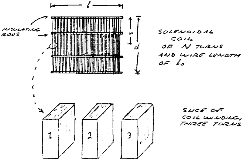
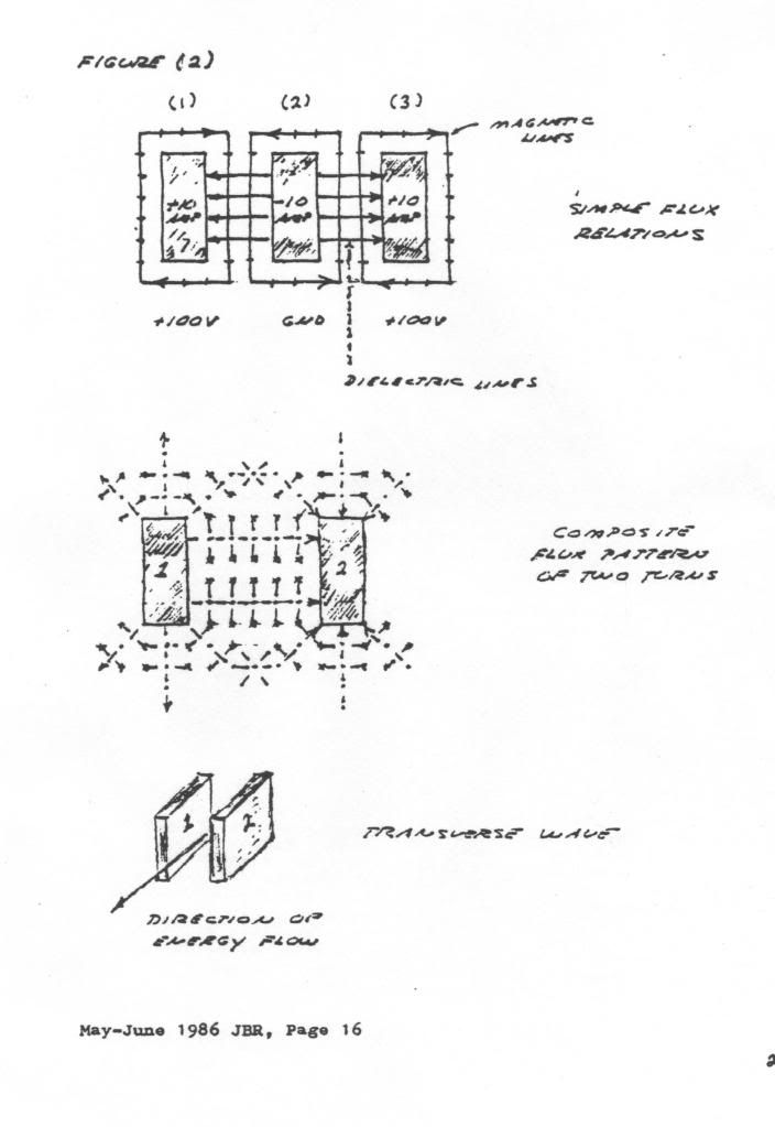
    There are four distinct forms of energy stored in a winding,
    Magnetic Pair:

    L, Leakage Inductance, Henry
    M, Mutual Inductance, per Henry

    Dielectric Pair:

    C, Leakage Capacitance, Farad
    K, Mutual Capacitance, per Farad

    The Magnetic Distribution along the coil axis is given by

    (2) Epsilon to the square root of LM power. It is an exponential curve along the axis.

    The Dielectric Distribution along the coil axis is given by

    (3) Epsilon to the square root of CK power. It too is an exponential curve along the axis.

    LM an CK are time scalars hence it can be seen that these initial distributions at t = 0 give rise to complex energy exchanges because of the exponential space distributions. We have now a fourth order differential in space and time. Alice lands in Wonderland. Forget Maxwell, forget the Corums, dead ends, forget them once and for all!!

    Break, more to follow

    DE N6KPH
    Hi Trex, long time fan..

    I have some questions I have to clear up in mind while I am studying your work.

    Eq 1. is the gamma of your writings, broken down to [(S^2)/T] and [(T^3)/(S^4)], this is the basis for EM waves through space, of an LC form, that of light and other associated phenomenon. So then the imaginary roots are ways to

    Did you mean Mu to the square root LM and Epsilon to the square root CK, both CK and LM being coefficients of dielectric and magnetic that are between 1 and 0?

    Its interesting how RG shows up in the Heaviside eq, you describe it to be the scalar component, and how its also a scalar dimensionally (ohms * siemens) = 1. This is a scalar that uses both dielectric and magnetic units..

    And there is XB which is also a scalar dimensionally (H/s * F/s). However since only RG is the scalar component then XB must be the longitudinal wave.

    And when we look at LC which is electrical in nature, (Farad * Henry) = second^2. Why does time come out to be squared?


    Now some answers to give (or rather have straightened out):

    1. How big is a planck, it is unity, it is the true individual unit of energy.

    2. How many Q/s are equal to one W-s? Is this even possible, you say that this Planck energy and classical energy are different! However dimensionally one (W-s) ^ 2 is in fact equal to one Q/s. How does this relate?

    3. What ratio of dielectric flux density and mag flux density are need to balance the contractive and expansive forces. Well the only equation that I can think of is the one you gave.. (C/m^2 * W/m^2 ) which is what set the poodle off barking..

    Some thoughts for now, I feel as If I have volumes of questions to ask!

    All The BEST!

    Leave a comment:


  • lamare
    replied
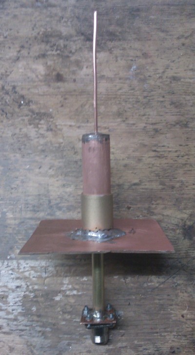
    I am working on the next version of my antenna. Some pictures here:

    Dropbox - Photos - Simplify your life

    Leave a comment:


  • lamare
    replied
    Video of measuring day

    Just found out a video of the "Heelweg 2012" measuring day has been posted on Youtube:

    Heelweg Microwave 14 January 2012 - YouTube

    You can see me at 1:15 and at 5:09 in the video..

    In the shot at 1:15, you can see me holding the antenna with the quick&dirty capacative 20 cents coin soldered on top of the whip.
    Last edited by lamare; 01-16-2012, 01:36 PM.

    Leave a comment:


  • lamare
    replied
    Originally posted by broli View Post
    That's some high quality professional experimenting you got going there. I hope the goal you set out to achieve will be achieved .
    Thanks. I'll do my best. I hope I can get access to the kind of measuring equipment I was able to use last saterday. You see, all I have myself is a 10 Mhz scope and two multimeters. I don't even have a transceiver or anything.

    So I took the opportunity to work with a vector network analyzer at the once-a-year measuring day of a regional radio amateur club with both hands, as I posted at another thread:

    Originally posted by lamare View Post

    Yes, it has a limited bandwidth, but I am pretty sure it also works at higher harmonics. And if this is an important ingredient, it will have to include higher harmonics, because it would need to work with impulses (steep rising edge, soft falling edge) rather than harmonic oscillations in order to be capable of energizing an iron core coil. According to Dollard, it is possible to create extreme impulses with TMT-like devices, even though I do not yet understand this completely. See my earlier post: http://www.energeticforum.com/renewa...is-motors.html.

    But we will know more about the bandwidth of the balun soon, because I will have my antenna analysed at january 14th. Then there is a "measuring day" by a ham group at about about an hours drive from my home, where there is measuring equipment available a radio amateur can only dream of:

    PAmicrowaves - Home

    A quick translation of the available equipment:
    - Sweepers 0-26 GHz
    - Spectrumanalyzers up to 26 GHz.
    - Spectrumanalyzer 10KHz - 3.8GHz + Tracking generator ; For measuring Filters, couplers, SWR and signals.
    - Measuring transmitter 10Khz - 3.3GHz (AM, FM, CW, and pulse)
    - SWR 5MHz - 3.0GHz (RF-SWR Bridge)
    - Spectrumanalyzer up to 325 GHz
    - Vector netwerk analyzer up to 20 GHz
    - Tektronix Videogenerator with sin x/x signal
    - Tektronix VM700 video measuring set
    - Barco Receiver I en II receiver/videodemodulator witht measuring probes for 23cm 13cm en 3cm,
    - NKF videodemodulator with baseband input for measuring baseband atv modules.
    - Spectrum analyser Agilent up to 3GHz.
    - Noise figure meter up to 24 GHz
    - Noise figure meter 47 GHz
    - Powermeter up to 76 GHz
    - Tuning unit 24 GHz Filters
    - Signal generator from 0 to 18,6 GHZ (Mar 2031 / HP8673) FM narrow- and wideband, so also ATV.
    - Spectrumanalyzer from 0 - 26,5 (of 31,8) GHz + Tracking to 2,7 GHz.
    - AM - 70 cm ATV generator
    - Counter to 24 GHz with rubidium stabilisation.
    - Powermeter up to 250 Watt up to 2,5 GHz.
    - Frequency standard 10 Mhz
    It would be interesting to frequency analyse a Gray tube, but then we would need a probe that is capable of measuring longitudinal dielectric waves propagating along the surface of the output wire connected to the grids, and we would need a proper termination impedance or something (may be a reflective metal plate?) connected to the wire as well.

    I have searched online for getting my own network analyzer, and there is one available that has been developed by a radio amateur, the VNWA:

    SDR-Kits
    SDR-Kits


    Covering 1 kHz to 1.3 GHz and powered from a PC USB-bus, the VNWA3 offers a dynamic range of 90dB up to 500 MHz and better than 50dB above 500 MHz.
    The price of a one of these is about 400 pounds, or about EUR 485,-. A version with some expansion board and calibration equipent in a nice suitcase comes at 534 pounds, or about EUR 650,-.

    This thing goes up to 1.3 GHz albeit with reduced accuracy, which is enough to do the job, but no more than that. Still, it is a considerable investment for me that won't be high on the priority list of the rest of the family....

    Leave a comment:


  • broli
    replied
    That's some high quality professional experimenting you got going there. I hope the goal you set out to achieve will be achieved .

    Leave a comment:


  • lamare
    replied
    Testing report

    Yesterday, I was able to test my antenna's using a vector network analyzer. The results were surprising and therefore interesting.

    First, we tested the naked antenna for which we already knew it had a nice SWR ratio at the designed frequency. After some tuning, we got an almost perfect SWR at the desired 1296 MHz frequency, and we made a plot of the measurement:


    At the left of the image, you see the nice dip at the designed frequency, while you see another, wider dip at around 1750 MHz. When we divide 1296 by 1,57, we should get the transverse resonance frequency of our antenna, which computes to 825 MHz, so the first higher harmonic should be at about 1650 MHz. If you woud consider the reflector plane as a capacative load, one would expect the resonance frequency to become lower, so it is interesting that the first transverse harmonic appears to be at a higher frequency than expected.

    After we tested this antenna, we went over to the design with wave guide. Of course, Murphey came along and it turned out that my connector was NFG and that the solder between the dipole and the reflector plane was broken, so I first had to heat up my soldering iron and fix that. Fortunately I took my soldering iron along and there was a guy selling the right connectors for a nice price. It were used ones, but much better and cheaper than the new ones I had.

    When we finally were able to test the antenna with wave guide, we found out to my surprise that it did not come even close to any decent SWR at 1296 MHz. Hmm. Maybe I had to add some top-plate? Let's try that. I quickly pulled a 20 cents coin out of my wallet and soldered that on top of the whip, to make another try. NFG again.

    Then, more or less by accident, we found out that when we pushed the dipole antenna out of its socket into the wave guide, we DID get a dip.


    So, I completely removed the reflector plate and we did another measurement with the naked antenna. Again to my surprise, we did NOT see a dip in the SWR at 1296 Mhz.

    Then we moved the antenna into the waveguide, from the bottom. Like this:

    High-res version: http://www.tuks.nl/img/Lamare_Waveguide_probe.jpg

    This time, when we moved the probe/antenna into the waveguide, we DID see a dip, although it was very hard to tune the thing to 1296 MHz, because the lower part of the dipole was too short without the socket, and the socket was hanging loose on there and tended to slip away, etc. All in all, it was a bit touchy.

    Still, it was very interesting to watch the screen when moving the antenna in and out the hole in the bottom of the waveguide, and it seemed that the length of the part of the dipole inside the waveguide determined the frequency of the dip. The more of the dipole that stuck out at the bottom, the higher the frequency of the dip.

    Another observation was that the length of the wave-guide did not seem to have any noticable influence on the size/place of the dip. This is confirmed by the "microwave antenna book":


    The attraction of a coffee-can feed is that it is so simple to make, a matter of finding the right diameter can and soldering a coax connector with probe to one side. Horn length is not critical, but should be more than one waveguide wavelength to eliminate any stray modes launched at the probe transition. My experience with probes in circular waveguide is that they are touchy to adjust and get right; the horn impedance varies with changes in both horn diameter and horn length, so any modification can upset the VSWR.
    BTW, the diameter of my waveguide was 10,5 - 11 cm, which means it should NOT support any normal waveguide mode at 1296 MHz:

    The horn must be large enough for the lowest order waveguide mode, the TE_11 mode, to propagate. The cutoff wavelength for this mode is 1.706 × Diameter so the minimum waveguide diameter is 0.59 λ.
    According to this, at 1296 MHz, our waveguide should have a diameter of AT LEAST 300/1296 * 0.59 = 13,7 cm. So, the fact that we DID get a nice dip at around 1296 MHz is very interesting...

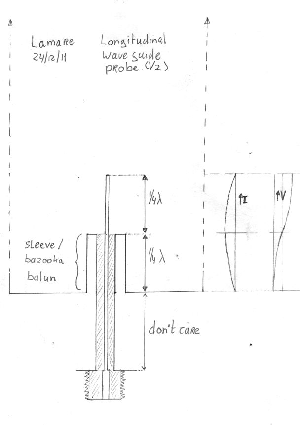
    Of course, we did not have a proper mounting of the probe or anything, but we did manage to make a nice plot of the situation skeched above:


    Interestingly, when I moved the antenna without reflector plane into the outer shell of the waveguide, just a hollow tube, we did NOT see a dip around 1296 MHz.

    So, it seems that the reflector is necessary in order to get the longitudinal wave to radiate, because the antenna without ground plane did not seem to produce anything near a decent SWR, which was measured by measuring the impedance of at the connector of the antenna, btw.

    It could very well be that the antenna without reflector DOES resonate, but NOT radiate, something I was worried about before:

    Originally posted by lamare View Post
    you have to realize that an important characteristic of longitudinal dielectric waves is that they propagate along the direction of the conductor, whereby the conductor acts as a wave guide.

    And since the wave is guided along your wire, it does not radiate away from your wire just like that. It keeps on propagating back and forth along your wire / wave guide. While this may raise some problems for me with my moon bounce experiment, it is a very nice characteristic for extremely low-loss energy transport.

    This is also possible with a so-called E-line ( Directory contents of /pdf/Patents/Elmore/ ) which is basically a transverse magnetic, longitudinal electric propagation mode that still has a magnetic component ( http://www.energeticforum.com/renewa...tml#post172991 ), but the longitudinal dielectric wave we are after does NOT have a magnetic component.

    It appears that in order to get the TM magnetic mode to propagate along an unshielded wire you need "launchers/catchers" ( http://www.tuks.nl/img/launcher.jpg ) , while for the longitudinal dielectric wave you don' t need them. Otherwise Tesla's one-wire transmission system would not have worked....

    To sum this up: longitudinal dielectric waves propagate at a speed much faster than transverse waves, have no magnetic component and don't radiate away from a wire but rather follow it as in a wave-guide.
    Last edited by lamare; 01-19-2012, 03:32 PM.

    Leave a comment:


  • madhatter
    replied
    I wanted to bump this thread and see if you've made any further progress.

    Also I was doing a bit more research and reading through Heaviside late last night I came across an interesting note, "Electrical notes Volume 3 Page 89"

    "There are several cautions to be expressed regarding the
    above. First the investigation has no reference to ordinary
    waves along wires. They do not behave in the above way, even
    if all resistance were done away with. The above waves are
    forced waves, whether u be less or greater than v, although
    only in the latter case is there permanent activity on the
    average. If we want to represent waves of this type along
    a wire, we require a continuous distribution of impressed
    electric force along the wire, or something equivalent. That
    is, the wire is to be a source of energy, instead of a sink, as
    is usually the case with waves along them, for the loss of
    energy by radiation of the heat is a separate matter, which
    does not come in question."

    in this same volume of papers Heaviside also talks about that induction can be absent when there is an infinite in length in the plane, then there is no way for it to terminate and thus it can not develop. Given how k is transverse to C if the wave of k is moving faster than v then the field would not have a termination point and induction would be absent from the coil.

    I'm grossly simplifying here as I need to connect the dots with more formalism. However based on a number of things posted and read I see this,

    the geometry of the secondary with it's inter-turn spaced wires is specificaly done to remove coil induction and enhance the k factor so that the transverse longitudinal wave will emerge, the primary coil being of coax could be considered the 'tickler' it's function is to get the secondary coil to be the source of energy and not mutually inductive to the primary, the extra coil is other node point for the wave and this increases the tension needed to keep the secondary as the source.

    now this brings up the point of one of Erics earlier posts in reference to the geometry of the antennae, the single wire is not going to have the ability to generate the wave, I'll do my best to dig up the relevant Eq from Heaviside to try and support my comment.

    Heaviside; Volume 3 page 30:
    chapter 9
    paragraph 465
    The steady Rectilinear Motion in its own line of a Terminated
    Electrified Line when u>v, and interpretation of the
    Impure Conical Wave following an Electron.

    Now if I'm wrong or off in anyway, Eric please point this out.

    Leave a comment:


  • lamare
    replied
    Originally posted by lamare View Post
    Today, I made a new probe according to the new design:

    The design:


    More photos here with some construction details:
    Dropbox - Photos - Longitudinal_Probe_V2


    Just got word from the ham that tested my antenna, and it is looking good.


    The SWR (Standing Wave Ratio) in the upper limit of the band (1299 MHz) is nearly perfect, while at the lower limit (1299 MHz) it is somewhat less, but that is logical.

    So, now we have to make a waveguide to put it in.
    Last edited by lamare; 01-03-2012, 02:55 PM. Reason: Added design img and url to photos.

    Leave a comment:


  • t-rex
    replied

    Leave a comment:


  • t-rex
    replied

    Leave a comment:


  • t-rex
    replied


    Last edited by t-rex; 12-27-2011, 10:28 PM.

    Leave a comment:


  • t-rex
    replied
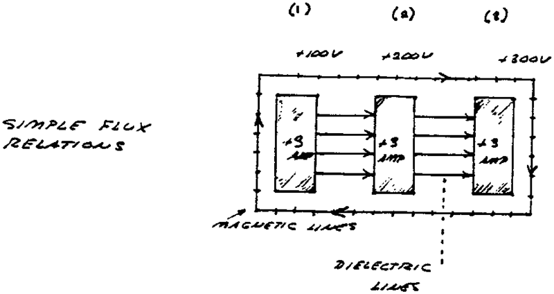
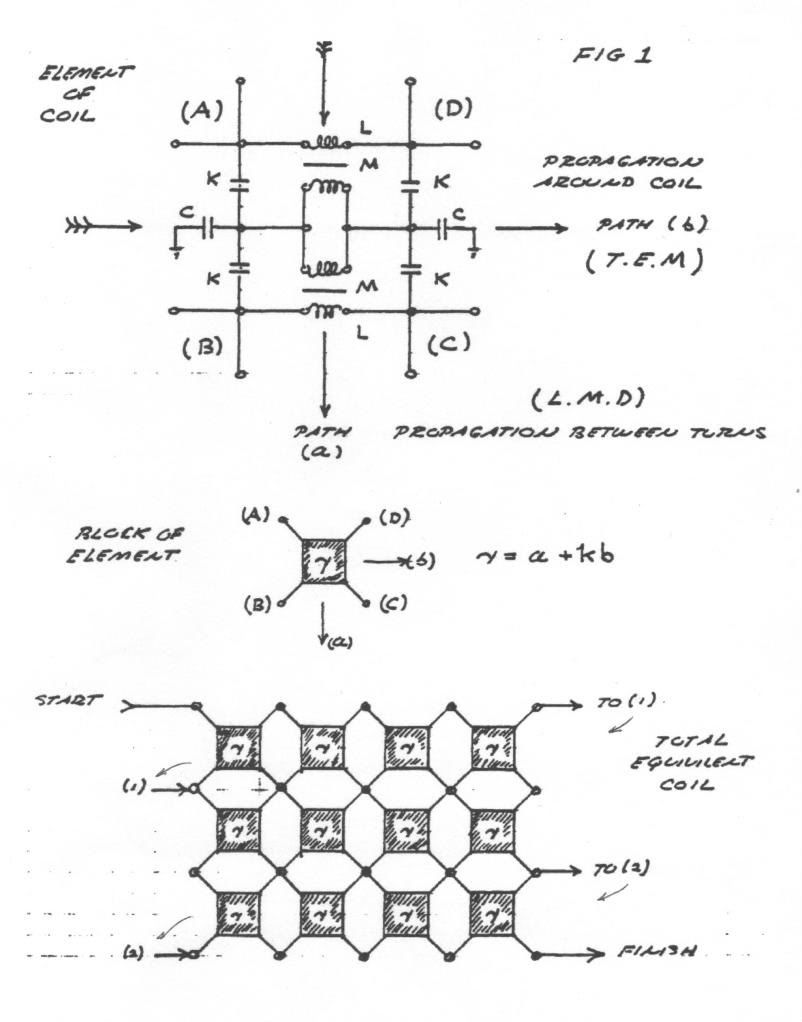
    Accompanying Pictures


    Last edited by t-rex; 12-28-2011, 05:14 PM.

    Leave a comment:


  • t-rex
    replied
    Lamare Discourse Continued

    Continuing with the four energy co-efficients:

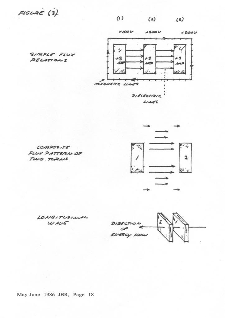
    LC, this gives the space scalar frequencies of oscillation, having no distribution in space, only in time (dot product)

    MK, this gives the "Tesla Vector" normal to the coil windings, a counter-velocity in per centimeters per second. (axial product)

    Also,

    L/K this gives the clockwise "Poynting Vector" around the circumference of the coil windings, a velocity in centimeters per second (cross product)

    C/M, this gives the counter-clockwise "Poynting Vector" around the circumference of the coil windings, a velocity in centimeters per second (cross product)

    (4) Hence (LC + MK(k^2)) + k(L/K - C/M)

    (5) a +kb
    The Heaviside relation for the dimension of space. For the condition of balance,

    (6) L/K = C/M
    The T.E.M. component vanishes and the "Poynting Vectors" cancel out. The resistance of the coil also cancels out giving rise to a very great magnification factor, as well as a pure longitudinal wave, a "Tesla Coil".

    Forget the Corums, the Bewelly-Dollard Theory has made them obsolete. Also it is my own belief that we have outgrown Maxwell. The path started by Tesla, Through Steinmetz and Alexanderson, to L.V. Bewelly has taken us far beyond the primordial physics interpretation of J.C. Maxwell. Leyden Jars and scales have grown to giant substation transformers and high speed oscilloscopes. We are entering a brave new world of electricity, electricity without electrons.

    Leave a comment:


  • lamare
    replied
    Originally posted by T-rex View Post
    It is generally considered that any wave must consist of a conjugate pair of energies, magnetic and dielectric let's say. Only then an interaction between time and space is possible. As I have shown recently it is through the union of a conjugate pair (L and C) that the dimension of time is produced. The propagation constant is then equal to:

    (1) Negative Gamma Square

    Having a pair of imaginary roots, plus j Gamma and minus j Gamma

    It is however that the JJ Thompson Longitudinal Dielectric Motions cannot have a periodic solution, there is one energy only, dielectric. This needs to be resolved.
    In its very essence, all electro(-magnetic) phenomena are motions in the ether, a medium with fluid-like properties in terms of it's capability of sustaining the propagation of electro(-magnetic) waves. Since transverse waves cannot propagate trough a fluid-like medium and magnetism is a rotational component in the ether, all electro-magnetic propagation must consist of some kind of space-bound dynamic flowing structure, which is some kind of wave phenomenon with a distinct frequency f. So, there is a one to one relation between all the parameters related to the phenomena, such as spatial distributed impedance and other parameters of the medium, and that frequency with has a dimension "per time".

    The propagation speed of such a "transverse spatial wave structure" has a maximum of c. Whereby c is not a Universal constant, but depends on the local parameters of the medium, which depend on things like the density and temperature of the medium.

    So, with all electro-magnetic phenomena, we have a maximum local propagation speed c.


    Now let's suppose what I posted above is true, that you can have "steady state" ether flow, electrostatic-only waves. Phenomena that propagate at a speed of pi/2 times local c. That is too fast a speed for electro-magnetic phenomena to keep up with!

    So therefore, you have wave phenomena that sees no inductance, only capacitance at its resonance frequencies. This is frequency dependent, but the frequency is such that the electro-magnetic wave with the same frequency can hardly propagate, because it does not resonate. So, you get a standing electrostatic wave, and a tiny electro magnetic wave. So, the magnetic component is suppressed significantly, which is why you can ignore the inductance for the longitudinal dielectric wave, at least in the particular situation whereby any electro-magnetic modes are out of resonance.

    Of course, this phenomenon also has a coupling to time trough it's frequency, but some parameters are different. Most strikingly, its propagation speed is pi/2 times local c, which relates trough the spatially distributed capacitance to spatial dimensions.
    Last edited by lamare; 12-27-2011, 09:13 PM.

    Leave a comment:


  • lamare
    replied
    Originally posted by T-rex View Post
    It is great to find a point of discussion, the Energetic Forum has been very boring to me, like talking to my own echo. However bickering like that with Light Ship seems to be more what interests everyone, a good fight!

    When considering waves on coiled windings, leave out the electrons, let us forget them once and for all. They are for electronic devices (RG) NOT for electrical devices (LC). Forget the electrons, forget it!
    Let's not go too fast with completely writing electrons of. I think electrons are a real phenomenon, but I think they have multiple distinct modes of existence. The most simple one is what we call a "particle", which in reality is a standing EM wave in the shape of a self-contained vortex structure. Something like this:


    I think these are the basic shapes any simple particle takes in the ether, whereby you can have multiple vortexes forming a complex structure. Depending on the specific structure, you get a netto rotation in the ether at some distance from the particle, which means a magnetic component, or you get canceling out of all rotational components, which means a non-magnetic particle, molecule or crystal.

    The electric field is a steady state flow in the ether, which occurs in the case there is a netto flow of ether trough the "pumping" vortexes. Since gravity is the gradient of the electric field, you can have mass-less and charge-less particles whenever the steady state ether flows cancel one another out.

    However, these kinds of structures describe "free flowing" particles. What is interesting is to think about what a covalent binding between two atom cores would be like. I suspect you get a very thin, long vortex, "an electron", which connects two "vacant electron orbits" (in reality: vortexes trough the center of the structure) from one atom to another. Depending on the direction of rotation of the vortex you get either a positive or a negative polarity.

    So, currents flowing trough a metal are not really just electrons jumping from one atom core to the next. What happens is that these connecting vortexes, trough which a steady state flow of ether is transported, are re-aligned and therefore the paths along we have steady state flows of ether trough the material are constantly re-adjusted. So, the electron jumping from one atom to the next is not a marble or something, it is more like a caterpillar with two suction feet at the end of it's body that flips trough the crystal structure of a conductor.

    This re-aligning of ether pumping vortexes phenomenon in a conducting material can support the propagation of electro-magnetic waves along the surface of the conductor at pretty high speeds, like 0.95 c in the case of waves along the surface of copper tubes.

    Interestingly, apparently it is also possible to get an ether flow trough a metal without this re-tubing effect, as shown by the Leedskalnin perpetual motion holder experiment:
    Edward Leedskalnin's Perpetual Motion Holder

    And I think in this configuration, you have a steady-state flow of ether maintaining the magnetic field, while there is no electron-based "current" flowing trough the material.

    So, I think we can have tube-like vortex structures running all the way round a transformer core ("field lines") trough which a steady-state flow of ether is flowing.

    I thinks it is possible to modulate this steady-state flow of ether without re-aligning the vortex structure ("electrons") in the material, which is what happens with longitudinal dielectric waves, because these propagate at speeds considerably higher than c, so re-alignment of "particles" is very unlikely, because these cannot go beyond the local speed limit c just like that.

    So, to me, electrons are kind of like the plumber's tubes that can be bent in any desired form and are capable of interacting with a medium with fluid like properties in various ways. This is the mechanism by which waves in the medium itself can be created and manipulated.

    Leave a comment:

Working...
X