Announcement

Collapse
No announcement yet.

Who performs the first longitudinal Moon-Bounce in history?

Collapse
X
 
  • Filter
  • Time
  • Show
Clear All
new posts

  • lamare
    replied
    Testing...

    Today, I made two antennas according to the new design. I scored two tin cans of exactly the right dimensions in my mother's kitchen

    I made a setup with my old MSX computer as video signal generator, a small 23cm ATV transmitter, an old analog satellite receiver, a television set and a "satfinder" power meter. Of course, this is nothing like professional measuring equipment, but at least I can do some screening.

    I did some experiments in my shack. First of all, I was able to transmit the test signal to the sat receiver and make it visible on the TV set, using pieces of about 5,7 cm wire as whip antennas. So, both the transmitter and the receiver work. The receiver even worked without antenna... Then I connected the power meter and played a bit with it. It worked as expected.

    Then I connected one of the waveguide antennas to the transmitter and also got a nice picture on the TV set. It wasn't completely stable 100% of the time, but I can't seem to program the receiver with my replacement remote control. However, it's good enough for my purpose.

    I played a bit with the wire antenna to try and get some idea about the radiation pattern. I also experimented with a small sphere antenna made of aluminum foil as replacement for the wire antenna. Finally, I played a bit with both waveguides connected, using the power meter.

    The results were mixed. At some points, it seemed that a strong signal was present along the desired radiation direction, along the length of the waveguide, and sometimes it seemed like most power went sideways as the simulation predicted. So, no clear results but all in all not too bad.

    However, I tested with a distance of about 2-3 meters using 75 Ohm coax cable (which is OK for the receiver which is 75 Ohm, but not for the transmitter which is 50 Ohm) and the transmitter nearby, so there may have been all kinds of reflections on the walls and wires in my shed, which make the measurements unreliable.

    So, the next step will be to take some measurements outside in the garden over a distance of about 20-30m.

    Now tomorrow is mother's day, so I don't think I will be able to do measurements tomorrow. We will have to save that for another day.
    Last edited by lamare; 05-11-2013, 09:55 PM.

    Leave a comment:


  • lamare
    replied
    Simulation results.

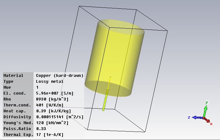
    I made some screenshots of the simulation results. First of all, a 3D view of the antenna:


    The project file for CST Microwave Studio can be found here:


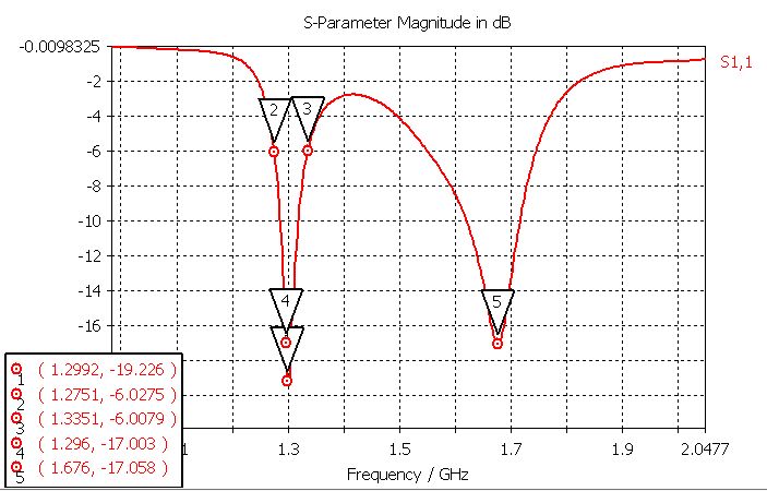
    Then, one of the most important graphs, the S-Parameters:


    S-Parameters for Antennas (S11, S12, ...)
    In practice, the most commonly quoted parameter in regards to antennas is S11. S11 represents how much power is reflected from the antenna, and hence is known as the reflection coefficient (sometimes written as gamma) or return loss. If S11=0 dB, then all the power is reflected from the antenna and nothing is radiated.
    Here's a handy page where you can convert the S-parameters into a/o VSWR and Reflection coefficient:

    VSWR - Return Loss - Reflection coefficient

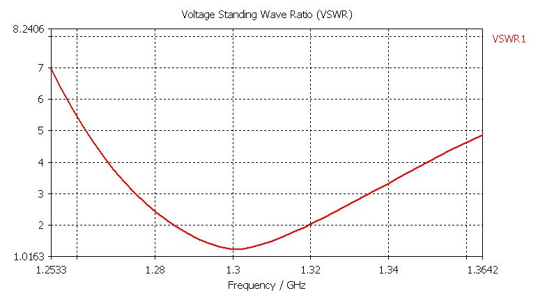
    For a return loss of -17 dB, we get a VSWR of 1.33:1 or a reflection coefficient of 0.14.

    For a return loss of -6 dB, which is the value used to determine the bandwidth of an antenna, we get a VSWR of 3:1 or a reflection coefficient of 0.50, which means that half the power sent to the antenna by the transmitter is reflected back to the transmitter. So, according to the simulation, this antenna should be usable between about 1275 and 1335 MHz.


    The VSWR plot:


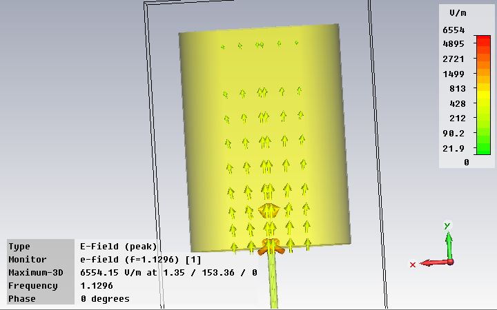
    The E(lectric) field at 1296 MHz as seen from the side of the antenna. As you can see, it points nicely in the length direction of the antenna:


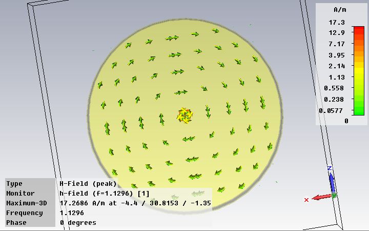
    The H (magnetic) field at 1296 MHz as seen from the open end of the antenna. As you can see, it points nicely in circles:


    What we see is what we expect to see when a TM_01 mode wave is present in the waveguide and it shows that power is being transmitted based on the near-field calculations which should be realiable, so to me this is an encouraging result. Encouraging enough to try and make a pair of these to see what they do in practice. If Eric is right, then we should see a longitudinal wave being transmitted right in the length direction of the waveguide:

    Originally posted by jpolakow View Post
    Note to Lamare from Eric Dol lard-

    [...]

    Steinmetz sphere equations in the "Transient Phenomena" book may be of use. The 1920 edition has the right equations. I think your sphere should be driven by a self resonant coil, cut short to resonate with sphere capacity. Sphere capacity equal to coil self capacity is maximum sphere capacity allowed. Use my formula in "Theory of Wireless Power". No guesswork here, just basic high school math. Forget the physics of gobble-gook. For "Can" antennas if you want what is known as a Transverse Magnetic, TM waveguide mode. Here the dielectric is longitudinal along direction of propagation. See "Radio Engineer Handbook", Terman, and "Reference Data for Radio Engineers" I.T.T. published. Here your waveguide modes are presented. One in particular is very interesting as its lossed decrease with frequency but it is very hard to excite this mode. Check this out as it is directly regulated to your efforts in "moonbounce". Show modes on forum for others to see!

    Also a "Tao" has his own great representation of the "Four Quadrant" "Eight Pole" representation on forum.

    73 DE N6KPH SK
    Looks like I should have listened to Eric right from the beginning and should have started with a TM mode waveguide instead.

    Either way, I learned a lot so far, even though I chose the hard way to do so.


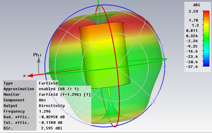
    Finally, the far field at 1296 MHz, which predicts that the antenna radiates the most energy sideways from the open end of the antenna:


    However, I don't trust the far field calculations of the simulator, because these do not account for longitudinal waves to exist.

    73's!
    Last edited by lamare; 05-03-2013, 08:24 PM.

    Leave a comment:


  • lamare
    replied
    As I posted on the Eric Dollard thread, I did some calculations and simulations with a TM_01 mode waveguide:

    Originally posted by lamare View Post

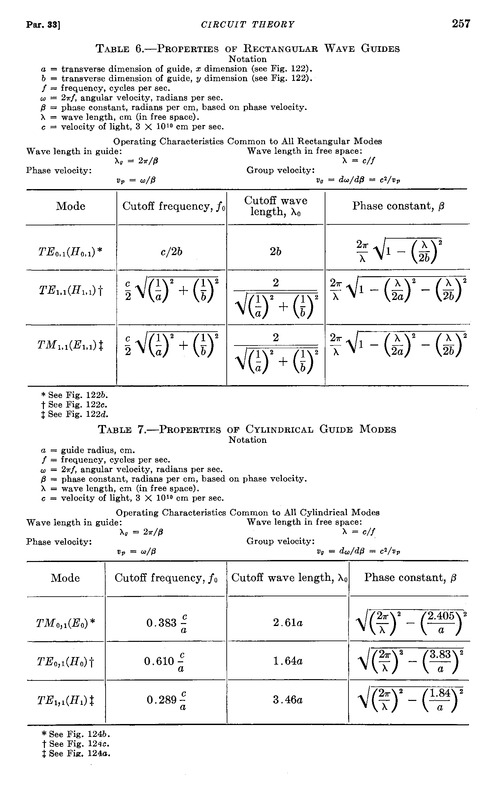
    Further, I finally found some time to work on the moon-bounce project again. I simulated a TM_01 mode "cantenna", whereby I chose the radius to be 10 cm, thus a diameter of 20 cm. For that diameter, we get a "group velocity" of sqrt(3) times the speed of light using the formulas from Terman's Radio Engineers Handbook at the design frequency of 1296 MHz:


    When I take the length of the waveguide to be 3/4 of the group wavelength (about 27 cm, IIRC), I get a nice dip at the design frequency of 1.3 GHz of about -16 dB in the s-parameters.

    The far-field simulation shows no radiation in the length direction of the waveguide, but the transformation by which the far fields are computed - after the near-field calculations are finished - does not account for the existence of longitudinal waves and is therefore unreliable.

    I will try and make two of these waveguides and perform some measurements the coming weeks/months. I have a low-power 23cm ATV transmitter, an old analog satellite receiver and a "sat finder" power meter, so I can do some experiments when I get all that up and running.
    I put the formulas from table 7 into a spreadsheet, which you can find here: http://www.tuks.nl/Spice/TM_01_Mode_...guide_calc.xls

    I calculated the dimensions using a velocity factor of 0.92, which was obtained by simulating a 1/4 wave whip antenna (the probe). The calculated length for the whip was 5.783 cm (calculating with c=299792458 m/s), while the optimal length as simulated was 5.336 cm.

    The calculated (and simulated) length of the waveguide is 27.7 cm for the design frequency of 1296 MHz. Furthermore, for calculating the desired group wavelength, I calculated with a propagation speed of sqrt(3) * c for the propagation speed of longitudinal waves, instead of the pi/2 * c I used earlier, because of the theoretical basis for that (see post quoted above).

    Some more on this velocity factor in this post:


    Update:

    Some documentation I used:
    Directory contents of /pdf/Reference_Material/TM_mode_waveguide/
    Last edited by lamare; 05-03-2013, 07:14 PM. Reason: Added note using sqrt(3) instead of pi/2.; updated url to xls sheet; added ref to docs.

    Leave a comment:


  • Dave45
    replied
    Hey Lamare not a problem

    Leave a comment:


  • lamare
    replied
    Originally posted by Dave45
    The cats out of the bag.
    Very cool stuff, Dave.

    I have seen some experiments with star-shaped coils before, but your vortex in water (at about 0 degrees Celsius??) is very interesting. How do you drive the coils?

    Either way, what you are showing is all about the nature of the magnetic field, which is a rotation in/of the aether. It is not directly applicable for my moon-bounce project, because the goal is to work with longitudinal waves which do not have a magnetic (rotational) component. See my posts here:


    I think your experiments connect nicely to the work of David LaPoint, who experimented with magnets in a vacuum chamber and was able to create a sun-like structure in the laboratory:
    David LaPoint - YouTube

    Very interesting video's.

    However, as I said, this is not directly applicable for my moon-bounce experiment, which is what this thread is about. So, if you want to discuss this stuff, I would appreciate if you start another thread in order to keep this thread a bit more on topic. Please do post a link to your thread, if you make one. I am interested in your work, but I'd rather keep this thread a bit on topic.

    Leave a comment:


  • s e t h
    replied
    \o/ go Dave45!!!

    Leave a comment:


  • Dave45
    replied
    The field is there its verified tech, the magnetron shows that, we just need to tap into it.

    Radar Basics - Magnetron


    Using the ring magnet the field moves from the center out but the Tesla egg it looks to move from the outside in, very interesting.

    Job 38:22
    Hast thou entered into the treasures of the snow? or hast thou seen the treasures of the hail,
    They use radar to detect how much ice is in a thunderstorm this tells them how much electrical charge is in the thunderstorm, they say the ice bumps into each other causing a charge separation.
    I personally think the ice kicks electrons from the earths magnetic field and this causes a charge separation.
    The ice is the perfect dielectric, I was worried about reflection but the ice should stop any kind of reflection.

    Leave a comment:


  • lamare
    replied
    Originally posted by Dave45 View Post
    In order to create a waveguide we need to eliminate bemf, the only way I can see to do this is use a dielectric to stop the field from collapsing into the coil. We have to ICEolate the coils
    I thought about that, too. There may be another solution, which is to use the same construction as I posted about before, the sleeve or bazooka balun:

    Originally posted by lamare View Post

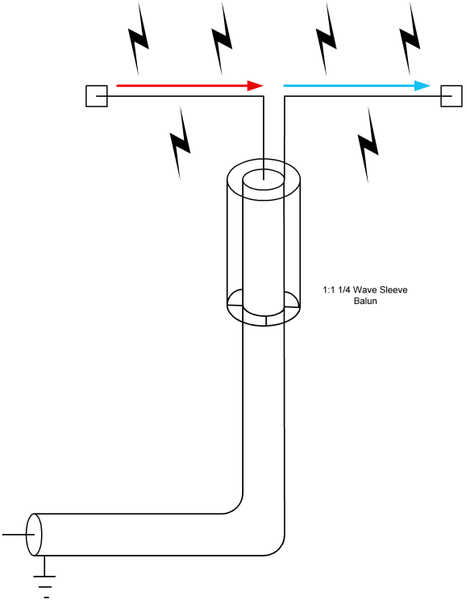
    The idea is to use a radiating "sleeve" or "bazooka" balun, meanwhile preventing the coax mantle to radiate:

    What about a balun?

    >Why is it some antenna's have baluns and others have not?

    The purpose of a balun is to prevent the coax cable from radiating. However, in order for the coax to radiate, there would need to be some radiative component along the axis of the coax to induce current in the coax. A symmetrical biquad doesn't have any such field component. Therefore, a balun is not needed.

    However, things get a bit different when the balun is used to feed an offset dish. The field is no longer axially symmetrical, and the coax is in the reflected field from the dish. Therefore a balun is probably a good idea with a dish.

    In general (with lots of exceptions), when the coax cable is in the antenna field, you need a balun. The real question is how much difference does it make? Most of the effect is in reducing VSWR, not increasing gain. With relatively low gain antennas (i.e. biquad with 10dBi gain), it probably might improve things perhaps a few tenths of a dB and is not worth the effort. However, with higher gain antennas, such as a dish, the lack of symmetry caused by a radiating feed could easily distort the pattern, create sidelobes, boresight errors, and VSWR.

    Also, some antennas are best constructed with 200 ohm feed points (i.e. Franklin antenna).
    Sector antenne voor Wifi ISM band (2,4GHz)
    Adding a 4:1 balun solves the balance problem and the impedance transform problem at the same time. You may therefore see a balun on some symmetrical antennas that don't normally require one, but where the impedance transformer action makes one convenient.
    Note that longitudinal waves are supposed to propagate along the axis of the whip and coax feed line....


    Dipole antenna - Wikipedia, the free encyclopedia
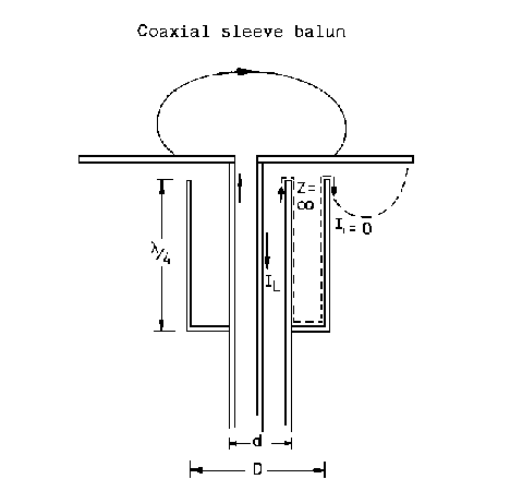
    At VHF frequencies, a sleeve balun can also be built to remove feeder radiation.

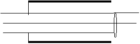
    * Another narrow band design is to use a λ/4 length of metal pipe. The coaxial cable is placed inside the pipe; at one end the braid is wired to the pipe while at the other end no connection is made to the pipe. The balanced end of this balun is at the end where the pipe is wired to the braid. The λ/4 conductor acts as a transformer converting the infinite impedance at the unconnected end into a zero impedance at the end connected to the braid. Hence any current entering the balun through the connection, which goes to the braid at the end with the connection to the pipe, will flow into the pipe. This balun design is impractical for low frequencies because of the long length of pipe that will be needed.


    Sleeve baluns
    Depending on which layout is mechanically easier to build and if you want the sleeve to radiate, the sleeve can be connected like this or reversed. In the layout below the sleeve is non-radiating. In a collinear antenna we might want to reverse the sleeve so it forms half of a dipole element.


    [...]


    From the above, we observe the following characteristics in a sleeve balun:

    1.) The highest possible choke sleeve impedance (largest ratio of balun sleeve diameter to outside of transmission line) is desired. We won’t have a good balun if the choking Zo (ratio of sleeve inner diameter to coaxial shield outer diameter) is small.

    2.) The balun requires the lowest possible loss over the length of the sleeve. It forms a transmission line from the inside of the sleeve to the outside of the coax. The coax jacket is a dielectric, so we need to keep a lot of air inside of the choking sleeve or the coax jacket will increase loss and reduce impedance, both being very undesirable.

    3.) The velocity factor of the sleeve, based on the dielectric between the sleeve and the shield of the coaxial cable we are trying to balance or choke, is very important to length of the sleeve.

    The following construction guidelines apply:

    The cable should have a good low-loss jacket or a very large air or low loss dielectric gap between the shield and the sleeve. Since energy is normally confined to the inside of a coaxial cable manufacturers are not concerned about jacket losses. They use outer materials with long life, not low RF loss. It is advisable to use a filler material with a high volume of air to maximize sleeve impedance and minimize sleeve losses.

    It is also advisable to use the largest practical diameter sleeve with the smallest diameter coaxial cable inside to maximize choking impedance.

    The sleeve length has to account for velocity factor of the sleeve, since the sleeve forms a coaxial transmission line with the outer conductor of the coaxial cable it is intended to choke or decouple.
    http://web.archive.org/web/201007170...io/sleeve.html (copy here: sleeve1 )

    The sleeve balun does not give any impedance transformation; it is a 1:1 balun. This is fairly easy to achieve at VHF. All that is required is a tube that is coupled to the outer of the coax at approximately 0.93 X l/4 from the antenna feed point.


    The ratio D/d should be around 2.5 to 4. The open end of the tube facing the antenna element should be as close as possible. In effect this tube is a shorted l/4, at it open end the impedance looking back down the coax is high, thus preventing RF current developing on the outer of the coax.

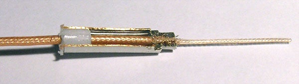
    I have made sleeve baluns using 15 mm copper water pipe and soldering a 'Free socket N' type connector onto it. The l/4 may be less than that of free space l/4, because of the close proximity of the outer tube to the coaxial cable. I found that 468 mm seems to work OK at 2 m, when using RG213 or URM 67.
    What's this weird antenna called? - RC Groups
    What people wanting DIY a sleeve balun should know, is the fact that the sleeve must be at some distance from the coax, and this empty space must be air, not a plastic insulator !

    The RC-cam antenna done using the coax mesh to simulate sleeve balun is one of the most popular but flawed example of how to not make this, because the balun part is so close to coax, making it zero efficiency.

    [...]

    Not quite correct. The distance between the outer conductor and the inner conducter need not be air. It can be any dialectric or insulating material, it is just that the spacing has to be adjusted to accommodate the dielectric constant of that particular insulation material.

    [...]

    The thing weird revealed:
    Note that the presence of a dielectric in between the outer conductor and inner conductor influences the propagation speed of the waves, which means the length of the sleeve must be adapted to that. And indeed, it is better to have some space between the inner and outer conductors, which is preferably air in our case, since we want the outer conductor to be part of our 1/2 wave dipole....

    Also see:

    Antenna Theory - Bazooka Baluns

    In principle, such a bazooka should also work when mounted around a TM mode waveguide. It appears to me that it should be possible to kill the magnetic component of the propagating TM wave using such a bazooka, or at least to prevent it from radiating the magnetic component out into space.

    But I have to think more about this. I will first see how far I can get with simulating a TM mode feed along the lines of these two documents:


    I am currently running a simulation with a waveguide of 23cm diameter, a probe of 1/4 lambda and a length of 48 cm. When that works out, I will see what happens when I add a "balun".

    Leave a comment:


  • Raphael37
    replied
    Originally posted by Dave45 View Post
    Tesla showed us the field
    Nikola Tesla - Columbus Egg - 1893 Chicago - YouTube
    In the radar basics website I read if you go against the field you gain energy but with the field you give energy to the field, with a magnetron we are giving energy to the field because the free electron spins with the field, but if a Tesla pancake coil were used we could force the electron against the field and gain energy.

    Using a ring magnet from a very large speaker and a sphere magnet inside a tube you will find the same field inside the core, it doesnt spin the sphere but does pull from the center out, whats interesting is in the vid above the field seems to pull towards the middle.

    Maybe Tesla has hidden the secret in plain site, an energy well all we have to do is iceolate and collect it.
    YES it is in plain site.
    Once you know what to look for, you cannot help see it, and its many variations/incarnations.
    The swastika Hitler used was based on the geometry of the 5x5 grid.
    Same size magic square as the 5x5 square of Mars and the Sator Square.


    Tesla the Magician and the Sator Magic Square | Alternative Thinking 37


    Well while we are on the topic of swastikas and swirly twirly whirly windings I want to point out something profound pointing us toward something that JUST IS.

    Well Dave how do I show that there exists a profound association between that Tesla video, the Columbus Egg demonstration in 1893 and our ancestors who hatched an IDEA at least 6000+ years ago?


    So we know this image 'exhibit A' is taken from Tesla's Columbus Egg demo ...
    Okay we can see how the Egg prefers to loiter around the center sweet spot too.

    Well it is not hard to establish that the swastika since time immemorial has represented to the consciousness of man, the sun and motion. Those two associations we can make at the very least.

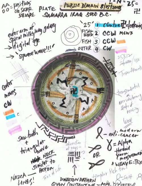
    So here is 'exhibit B', evidence from Samarra Iraq circa 4000+ BCE. We see it has positioned at the center a symbol representing a spin motion.
    a.k.a. as the swastika

    And this container is in fact in the shape of a bowl too!


    How deep down the swastika hole do you want to go?

    Swastika Plate 5000 BC is a Model of the Milky Way | Reconciliation of Science and Religion


    To give you an idea of where I have taken this AHA.
    The swastika, Tesla, String Theory, Knights Templar are all on the same page hovering around the same ideas.

    Story of the W and Z – Sator Square – Twistor String Theory – Penrose & Schwaller & Witten & Wedekind | Alternative Thinking 37

    cheers,

    Leave a comment:


  • Raphael37
    replied
    Originally posted by Dave45
    another winding configuration
    interesting photo dave

    you might be interested in this video then...


    video >> The Armenian Wheel Of Eternity - YouTube

    namaste

    Leave a comment:


  • Dave45
    replied
    Tesla showed us the field
    Nikola Tesla - Columbus Egg - 1893 Chicago - YouTube
    In the radar basics website I read if you go against the field you gain energy but with the field you give energy to the field, with a magnetron we are giving energy to the field because the free electron spins with the field, but if a Tesla pancake coil were used we could force the electron against the field and gain energy.

    Using a ring magnet from a very large speaker and a sphere magnet inside a tube you will find the same field inside the core, it doesnt spin the sphere but does pull from the center out, whats interesting is in the vid above the field seems to pull towards the middle.

    Maybe Tesla has hidden the secret in plain site, an energy well all we have to do is iceolate and collect it.

    Leave a comment:


  • Dave45
    replied
    I forgot about the z pinch it applies here as well

    Reflection is a problem, pure gold would be the least reflective material I can think of.
    Maybe now we can understand why gold has been so coveted down through the ages.

    Leave a comment:


  • Dave45
    replied
    If these toroids were wound using the Rodin configuration we would have a spinning vortex, like water down a drain.
    enough rattling today
    Last edited by Dave45; 04-27-2013, 01:17 PM.

    Leave a comment:


  • Dave45
    replied
    In order to create a waveguide we need to eliminate bemf, the only way I can see to do this is use a dielectric to stop the field from collapsing into the coil. We have to ICEolate the coils
    A stacked toroid configuration to funnel energy into a collection grid.

    The field that causes bemf is collected in the grid, never collapses into the coils, the coils are allowed to create the flywheel.
    Last edited by Dave45; 04-27-2013, 01:16 PM.

    Leave a comment:


  • Dave45
    replied
    If our coil is wound on a toroid (flywheel) the bemf stops the kick by changing the magnetic field direction.

    Leave a comment:

Working...
X