
 Tweet
Tweet
I'm trying to understand the secondary coil design. It sounds like Nhopa is saying that Tesla's colorado springs notes describe a long thin secondary, yet Eric's notes in intro to tesla coils describe the secondary as a spiral or short fat coil. Anyone want to weigh in on which is correct? The picture on the front of Eric's intro to tesla coils looks like a long thin coil, so I'm confused on what is correct.
-
Last edited by skaght; 01-28-2012, 04:10 AM. -
The Colorado Springs coil (the one in most pictures) secondary is 15 metres diameter and about 2m high. Or short and fat.Originally posted by skaght View Post
A flat spiral coil is another coil altogether. In context it means you can either build one or the other.
May I recommend going to the source of the information rather than interpreting interpretations
[edit] I suppose the simple answer to your original question if you don't want to have to make an extra coil is to make a flat spiral coil instead.Last edited by dR-Green; 01-28-2012, 03:54 AM.http://www.teslascientific.com/
"Knowledge is cosmic. It does not evolve or unfold in man. Man unfolds to an awareness of it. He gradually discovers it." - Walter Russell
"Once men died for Truth, but now Truth dies at the hands of men." - Manly P. HallComment
-
Hallelujah!
WOW!Originally posted by T-rex View Post
That mega post by Mr. Dollard answered quite a few complex and downright perplexing issues that I was trying to resolve when doing the math on impulse discharges (of L or C or both one into the other)! Also the concept of the battery as having characteristics of both a capacitor and inductor rings true with me, I have been trying to resolve how to analyze the storage battery (in the electrical sense, or non-chemical sense) for quite some time and came to similar but not quite as refined results. I think one word would sum up my opinion of what was recently posted, Hallelujah! I feel as if that post filled in a fair bit of what I was unsure about in my post "Question On Plank, Q with Respect to an Impulse Discharge of L or C into r".
Furthermore, we now have new insight into the whole negative resistance / negative conductance situation, I personally HATE the term NEGATIVE RESISTANCE -r (generally this is actually a non-linear/non-ohmic resistance and has nothing to do with excess energy), negative ohms is acceptable by my standards though. With whats presented by Mr. Dollard we at least can now call negative ohms & siemens, Receptance H & Acceptance S, something that makes me very happy indeed. This should elucidate, if the concept is fully understood and used properly, interesting phenomena in an electrical circuit whereby there is an excess of energy (or the "load" acts as a "source").
Finally we see some use of a versor operator and its application and (inferred) theory of its use mathematically in electrical situations! I think there's a lot yet to be said or done with this mathematical tool. Hopefully we will get another post with its usage soon from Mr. Dollard.
In conclusion I feel everyone should read that post a few times over, it has some gold nuggets that are sure to give new insight and potential use in future "practical" real life situations.
Garrett MLast edited by garrettm4; 01-29-2012, 11:33 PM.Comment
-
Thank you dR-Green for the help with my questions. I guess no.:2, the "well as a ground" still needs to be resolved. It seems to me from the foregoing discussions, that the best answers to questions is experimenting. After all Tesla's Colorado Springs Notes are about experimenting. Tesla did'n have all the answers but deducted many from the various experiments. I also apologize for my mistake about the diameter to lenght ratios of the secondery coil. Most of the "extra" coils have a D to L ratio of larger than 1. For example from the Notes on p.110: 2' dia to 6' lg, p.160: 6' dia to 12' lg. However the cage type "extra" coil shown on a few pages in the Notes are indeed close to the 1:1 ratio.
I agree for first hand information one must be going to the source. In our case the real McCoys are the Colorado Spring Notes and Eric Dollard's publications on the subject.
@skaght: Things can be confusing and that is the reason why I have lots of questions. I would recommend obtaining a copy of the Notes as an onhand reference together with Eric's various publications on the subject.Comment
-
"image coil"
In Eric's notes, intro to tesla coils, he states that for plasma work you need an "image coil" between the secondary and ground to provide 180 degree phase shift. I would prefer not to build two tesla coils as he seems to suggest later on for plasma work, since I'm not positive of all the design parameters. Would a simple coil with 1/2 wavelength resonance work as an image coil? Or does "image coil" literally mean that the coil is a "mirror image" of the secondary and extra coil? I've been searching for a definition of an image coil and I'm not finding much.
Does anyone know the definition of the term "image coil"?
Thanks!Comment
-
Hi,Originally posted by skaght View Post
He mentioned AFC - automatic frequency and phase control.Probably need to keep resonance all the time or need to check phase between 2 coils, even load changed. to do that he have 2 same secondary coils. He is measuring phase of 2 secondary coils and based on that is controlling a voltage controled oscillator - VCO.VCO is generating a main fequency and as well a synchronization pulses for pulse modulation of main frequency.Phase discriminator is checking a difference in phase and frequency of 2 signals.It is used in nearly all RF receivers.
On Page 13 of that book is :
"To confine the energy an image coil
(180 degree shift) must be connected to the earth terminal. Making this
arrangement in a horseshoe configuration produces intense dielectric
flux and displacement current that is quite usefull for plasma work."
The electrical length is 360 degrees at the fundamental of oscillation.
I think that image coil is to keep total electrical lenght in 360 degree. then need to control a phase of that 2 coils to get strongest effect.Comment
-
Versor Operators Decoded, With Respect to DC & AC Circuits Pt1
Foreword:If you already have a good grasp of the Dollard type versos then this whole post can be skipped over.
Roots & Powers; Exponentiation Cliff Notes:The Roots of Unity; Negative & Imaginary Numbers Cliff Notes:Continued in Part 2Last edited by garrettm4; 02-02-2012, 10:12 PM.Comment
-
Versor Operators Decoded, With Respect to DC & AC Circuits Pt2
Continuing with Part 2
Versor Operators; Rotation about an Axis:When a versor and a vector which lies in the plane of the versor are multiplied, the result is a new vector of the same length but turned by the angle of the versor. When the arc of a versor has the magnitude of a right angle (π/2), it is then called a Right Versor. Right Versors have a zero Scalar part, and thus, are Vectors of length one, or Unit Vectors.
Outside the context of quaternion theory, in normal algebra and geometry, the term Versor is often used for a Right Versor. In this case, a Versor is defined as a Unit Vector indicating the orientation of a directed axis in a Cartesian coordinate system.
Dollard type Versorsthey generally have little to no relation to one another
i.e. the horizontal or "x" axis is now the imaginary axis and the corresponding vertical or "y" axis is now the real axis.Note: The coordinates used for the above arbitrary vectors, is in the standard format where (x,y) denotes the exact position on the grid, and where the length or MAGNITUDE of the vector is determined as the distance from the origin (0,0) to that point.
The notion of whether the RESULTANT rotation, by k^n, is NEGATIVE (-) or POSITIVE (+), has strictly to do with the "NORMAL" direction of rotation of the arbitrary vector. In the special case of vectors E & I, the INDUCTIONS of the Magnetic & Dielectric fields, we find that they counter rotate, and thus form a pair of counter rotating vectors, having a double frequency PRODUCT (EI=P) called PowerContinued in Part 3, The subtopic of "AC Power" is discussed in minor detail, which shows the relevant "cause & effect" brought about by a rotation by versor k.
Garrett MLast edited by garrettm4; 02-03-2012, 02:53 AM.Comment
-
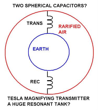
Could this be what tesla had in mind?
the earth as a spherical capacitor inside the air as an outer spherical capacitor with the coils connecting the whole thing as a gigantic resonant tank?
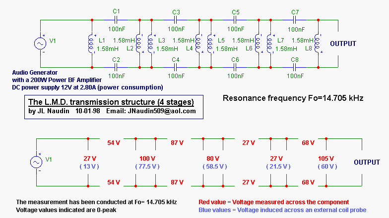
and does anyone have an opinion on what naudin did here?

 You may notice that the Magnetic energy is in Space CONJUCTION with the Dielectric energy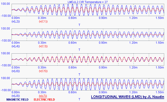


appears he replicated Erics setup in part.
see the rest here
Has anyone talked with him about this and how he made those conclusions?
I know Eric got higher voltage, but according to naudin as shown above greater power out as well?
Find that a bit difficult to accept.
Last edited by Kokomoj0; 02-01-2012, 03:46 AM.Comment
-
What is the big deal? Eric Dollard has done this demonstration almost 30 yars-ago, and the first time before anyone else.Comment
-
"Doesn't matter how many times you kick the coyote in the head, it's still gonna eat chickens". - EPDComment
-
Versor Operators Decoded, With Respect to DC & AC Circuits Pt3
Continuing with Part 3
Note: While this portion of my post is not paramount for the understanding of the AC versor k, I do feel the subject of AC Power is quite mysterious for most people and thought I would attempt to shed some light on the matter.
AC Power; Complex, Absolute, Real & Imaginary:
Whether the current I or voltage E of the AC circuit is leading or lagging, by any arbitrary value (in degrees or radians), the resultant QUADRANT in which the vector of Power is located changes as a direct result. There exist four quadrants in the Cartesian coordinate system, which form the complex plane as seen on an Argand diagram, each quadrant can be thought to represent a specific condition or state of the electric circuit. These specific states are CONSTANT for ANY circuit whose PARAMETERS (L, C, M, K, g & r) DO NOT CHANGE in TIME. If the load of an AC motor increases or decreases a change in the MAGNETUDE of transferred magnetic energy from L1 to L2 via M causes a STATE CHANGE, thus a corresponding change in the POSITION of the Power vector. For the very SPECIAL condition of of a storage parameter (L or C) whose value changes PERIODICALLY in time, we will find that the Power vector will have two or more PERIODIC positions in TIME. Determined by the state of affairs present, this special condition has the possibility to REMOVE energy from the circuit (with out associated loss as heat) while also having the possibility of INTRODUCING energy into the circuit (from the fields of induction OUTSIDE the guiding wires).
As is shown in Mr. Dollards (excellent) book Symbolic Representation of Alternating Electric Waves (Pages 28-29)
The Real & Imaginary, two Axes having Four Directions:
(+1) 0, Consumption of Active Energy
(+j) 1, Consumption of Reactive Energy
(-1) 2, Production of Active Energy
(-j) 3, Production of Reactive Energy
If the vector of Power is found to be on one of the axes, it is seen to have a 100% condition of any one state, dependent upon its direction. i.e. 100% consumption of active energy or 100% production of active energy.
If the vector of Power is found to lie outside the vertical and horizontal axes, such as between axes (which is the usual case), it will be found inside only one of four quadrants.
The Corresponding Quadrants:
(+j,+1) I Consumption of Active & Consumption of Reactive Energy
(+j,-1) II Production of Active & Consumption of Reactive Energy
(-j,-1) III Production of Active & Production of Reactive Energy
(-j,+1) IV Consumption of Active & Production of Reactive Energy
The exact placement of the Power vector inside any one quadrant will yield any arbitrary GRADIENT of the above listed states. This causes the complex problems associated with MEASURING the MAGNITUDE of the Power vector. This is because we have EIGHT possible conditions in which the state of "Power" can be in (four single states, on an axis & four dual states, between axes), thus no single measurement will suffice in giving the total measurement of Power.
Hence the four Measurements of AC Power:
1 Apparent Power..(Watt Meter + VAR Meter)..(Complex, Real + Imaginary Axes Value)
2 Vector Power.....(Volt Meter * Amp Meter)...(Absolute, sqrt(Real^2 + Imaginary^2) Axes Value)
3 Active Power.....(Watt Meter)....................(Real Axis Value)
4 Reactive Power..(VAR Meter).....................(Imaginary Axis Value)
The length or MAGNITUDE of the Power vector is determined by the distance from the origin (0,0) to its location (x,y), this length is what we "MEASURE" when using our watt, var, volt & amp meters. In the case of Apparent Power we add the length of the active power (0,0) to (0,y) to that of the reactive power (0,0) to (x,0), this forms a complex number which cannot be found with only one measurement. This geometrically analyzed, would be seen as a corner of a square or rectangle. For the measurement of Vector Power we take the actual length of the Power vector, or its distance from (0,0) to (x,y). Geometrically this forms the hypotenuse of a right triangle, whereby the length can be solved with use of the Pythagorean Theorem, or a^2+b^2=c^2. Hence the associated (Vector Power)=sqrt((real axis length)^2 + (imaginary axis length)^2) formula. Finally for both the Reactive & Active Power, the measure of the vectors length or magnitude is simply from the origin (0,0) to the associated location along the real (0,y) or imaginary (x,0) axes.
The material written above, should assist in the understanding of the affects a rotation by versor k can have on the double frequency Power vector, or its source vectors E & I. While only generalities are used, they do serve to guide you to the right solution when doing calculations and measurements of a specific circuit arrangement.
Note: If any errors or unintelligible sections are found, send me a PM and I will correct them ASAP.
Garrett MLast edited by garrettm4; 02-02-2012, 10:44 PM.Comment
-
Notes on the Crystal Set
Notes on the Crystal Set
When measuring the velocity difference between underground and our ground, the two seperate receivers can be brought into phase unison by the use of a test oscillator. Both receivers must have a primary tank circuit, here you can place your measurement equipment.
The detected AM output, audio frequency, signal is immune to receiver phase shift. This is a property of A.M. detection. Use the audio to measure propagation delay.
Wind all coils in the same direction, this is a must! Brass is a very good primary material, good depth of penetration at broadcast frequencies. Wires and clip lead interconnection are the "Road to Absolute Defeat." Coils and Condensers must be merged into each other in broad surfaces. Stacked metal plates on insulators makes good condensers. Transmitter air condensers are good, vacuum condensers are the best. A number of small condensers are better than one big one, less stray inductance. Stray inductance is fatal to success! For smaller units silver mica condensers are the only way, use no others. Paralell them on a low inductance bus.
Do not get sidetracked, experimental and auxilliary coils as well as patent diagrams will get you stuck in the sand forever. The finished Colorado unit dimensions are all in the notebook. It is all there, look at it, not the diversions, and remember everything you thought was Tesla is the exact opposite. It is there; one or two turn primary; a 20% height/width secondary; and a 100% height/width extra coil, all there, wire size, turns, all there, can you find it? It then can be scaled to any frequency and any KVAR capacity within wavelength conditions.
As your unit gets perfected the signal gets stronger and stronger, then diodes start burning out. We then are reaching the engineering objective, that is to light a number 327 pilot lamp. Not much power but too bright for Einstein.SUPPORT ERIC DOLLARD'S WORK AT EPD LABORATORIES, INC.
Purchase Eric Dollard's Books & Videos: Eric Dollard Books & Videos
Donate by Paypal: Donate to EPD LaboratoriesComment
-
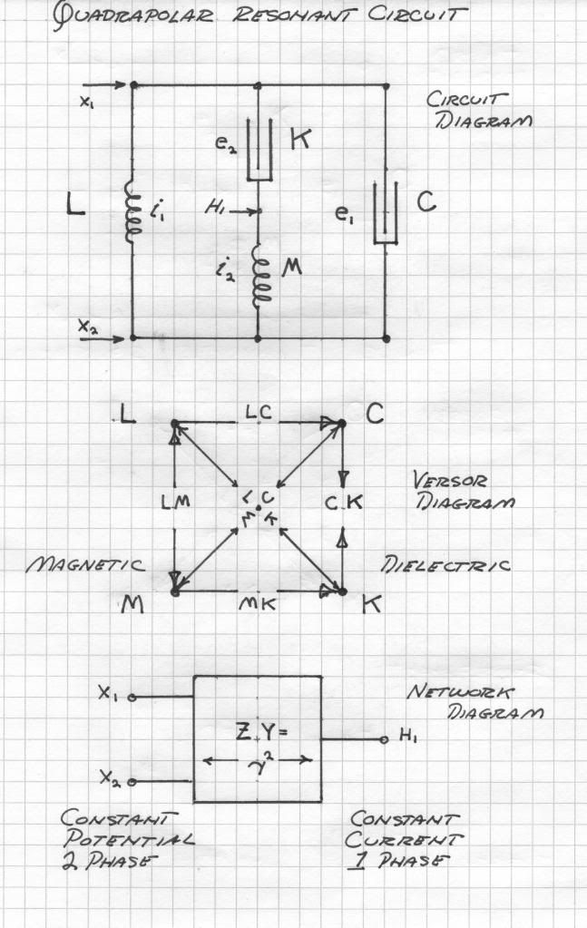
Quadrapolar Resonance
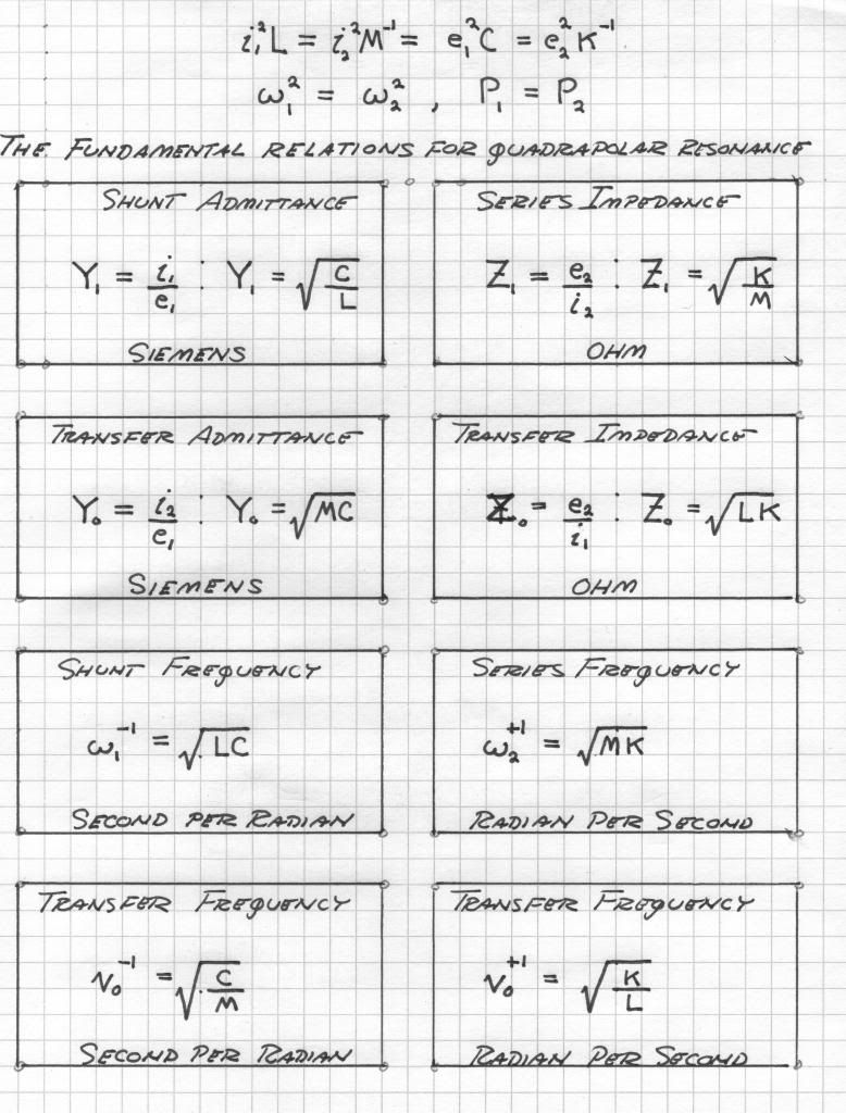
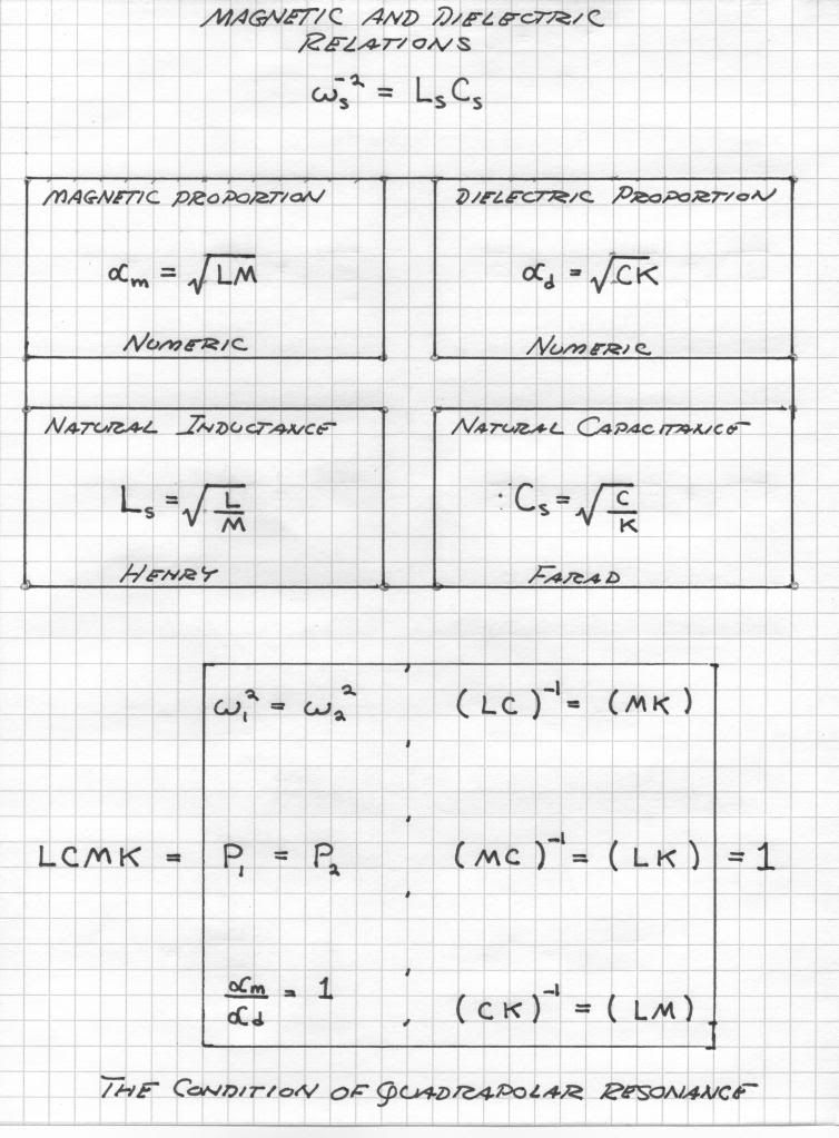 SUPPORT ERIC DOLLARD'S WORK AT EPD LABORATORIES, INC.
Purchase Eric Dollard's Books & Videos: Eric Dollard Books & Videos
Donate by Paypal: Donate to EPD LaboratoriesComment
-
Thank you! I've been trying to resolve the inductance, capacitance and resonance of a coil and it's dimensions to the wavelength. I have not till now read thru the springs notes. Tesla's notes are quite clear on the relations and how it's derived. First time I've seen the relationship explained.Originally posted by T-rex View PostComment
Comment