This forum is preserved as a permanent archive. The community continues at eMedia Press.

Announcement

Collapse
No announcement yet.

Peter, whatever happened with Eric P. Dollard?

Collapse
This topic is closed.
X
This is a sticky topic.
X
X
 
  • Filter
  • Time
  • Show
Clear All
new posts

  • Longitudinal wave antenna

    I was loking at Eric Dollard's video "Tesla longitudinal electricity" with Tom Brown and Peter Lindemann. The question is about the antenna construction. The wire, rather the coaxial cable, for the secondary coil is wound on 16 spokes originating from a central hub. Each spoke is notched on the top (and may be also on the bottom?), so as the wire wounding fits in these notches. The way Peter Lindemann explains it that the first turn goes on the "bottom" and the second turn on top of the first and this sequence repeats about 20 times. The way Lindeman explains it is not clear to me. Are there two turns in each notch on the top of the spokes or one turn in the top notch and the second turn below the top one in the bottom notch. This latest configuration would result in two parallel flat spiral coils seperated roughly by the thickness of each spoke. Any insight is welcome.
    Also a question about the secondary coil made up of 3 - 1" wide by .010" thichk bronze strips. When I calculate the surface area, as advocated by Eric Dollard, of the primary do I calculate just the outside area of the coil or individually all three strips making up the coil? Somehow they don't ad up either way.
    One more question concerning the equipment Tesla used for his Colorado Springs experiments. He had among other things a Westinghouse generator/transformer rated abut 26HP. If one would like to repeat (very carefully) some of the experiments at home on a much smaller scale, what size transformer would one need, i.e. input and output Voltage rating and Amper rating. Would a transformer rated, say between 10 to 20 amp, be sufficient at what output Voltage?
    Comment


    • Originally posted by Nhopa View Post
      The way Peter Lindemann explains it that the first turn goes on the "bottom" and the second turn on top of the first and this sequence repeats about 20 times. The way Lindeman explains it is not clear to me. Are there two turns in each notch on the top of the spokes or one turn in the top notch and the second turn below the top one in the bottom notch.
      There are two turns in each notch, so the wire length is effectively doubled for the same size base. Wind one complete turn, then wind the next turn on top of the one you just did. When you get back to the start again move into the next notch and repeat 2 turns again. Each notch is to have two turns in it.

      The easiest way to match the windings is by weight. With a flat spiral coil I put the primary on first so I know how much length I need and cut it. Then I put this on the scales and weigh out an equal amount of thinner wire for the secondary, compensating for the lead-in and lead-out wires etc. I aim to get the weight of the copper in the winding itself as close as possible, excluding the bits I need to connect it with.
      http://www.teslascientific.com/

      "Knowledge is cosmic. It does not evolve or unfold in man. Man unfolds to an awareness of it. He gradually discovers it." - Walter Russell

      "Once men died for Truth, but now Truth dies at the hands of men." - Manly P. Hall

      Comment


      • My timing sucks

        Eric we need to talk.

        Zane


        Originally posted by T-rex View Post
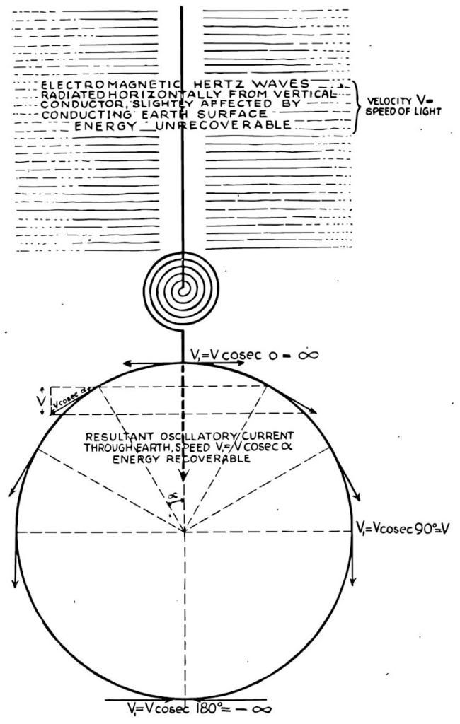
        Tesla's Diagram of overground vs underground waves Hetzian/Telluric

        Note Telluric velocity, a function of angle around the earth, it is a cosecant, infinity at the poles, luminal at the equator. Pi over two is the integral "velocity"


        Comment


        • There are some contest crystal radios that are hard to beat.
          The spider or diamond weave are going with the higher Q
          It would be nice show improvement but without Ham license your just receiving.

          Birmingham, Alabama Crystal Radio Group - 2009 Crystal Radios
          2 circuits with spider web coils
          Last edited by mikrovolt; 01-16-2012, 12:16 AM.

          Comment


          • However so lowly

            I am trying to accomplish the impossible without lifting a finger.

            Eric could you work in my lab?


            Comment


            • Originally posted by john_g View Post
              dR-Green

              Many thanks for the decode - I hadn't noticed the plate in your photo.

              Regards

              John
              You're welcome. Good luck
              http://www.teslascientific.com/

              "Knowledge is cosmic. It does not evolve or unfold in man. Man unfolds to an awareness of it. He gradually discovers it." - Walter Russell

              "Once men died for Truth, but now Truth dies at the hands of men." - Manly P. Hall

              Comment


              • SUPPORT ERIC DOLLARD'S WORK AT EPD LABORATORIES, INC.

                Purchase Eric Dollard's Books & Videos: Eric Dollard Books & Videos
                Donate by Paypal: Donate to EPD Laboratories

                Comment


                • Forces Upon Conductors, and the Planck (2 of 2)

                  Since the Transmission Line can now act both as an Inductor, and as a Condenser, the Resonant Exchange of Stored Magnetic, and Stored Dielectric, Energies is now possible. This is effected by the use of standing waves. Because the standing wave represents that part of the Electric Field not united into Electrification, in Plancks, the amplitude of this standing wave can be maximized by minimizing the unification of Dielectric and Magnetic Lines of Force. This is brought about by either, short circuiting the end of the line, or open circuiting the end of the line. Hereby no energy can escape eliminating the Traveling Wave. The Transmission Line now exhibits only Standing Waves and no part of the Electric Field gives rise to Electrification. In this condition the Stored Energy of the Electric Field will engage in an endless exchange of Energy between Magnetic and Dielectric Forms. This is a similar relation to that of the LC tank circuit. Since no part of the Electric Field on the line making up the Standing Wave unites into Electrification, it can be said that this part is an Imaginary, or Reactive, Component of the Electric Field. Since the Traveling Wave is the consumption of Power, as with resistance, this part of the Electric Field is united into Electrification, or Plancks. The traveling wave is a Real, or Resistive, component of the Electric Field. It then can be reasoned that the physical forces exerted upon the conductors of the Transmission Line are the result of Reactive Power, or stored energy, this contained by the Line. Hence in a condition of Resonant Energy Exchange in the Transmission Line, the Physical Forces upon the Conductors are maximum. These forces distribute themselves in a complex function of Length along the Transmission Line containing a Standing Wave. The condition of Resonance is maximized when a line is of such a Length as to take one half cycle of time to reach the distant end and reflect back to the sending end. This is called a quarter wave line. If the distant end of this Line is Short-circuited and the sending end Open Circuited, Powerful Resonance is developed. However, unlike a basic LC Tank Circuit, the waveform of the Line will be a Rectangular Wave, abruptly reversing polarity at the time rate given by its frequency of Energy Exchange. This important fact is very often overlooked.

                  In conclusion, the Electric Field of Induction contained in a T.E.M. Transmission Line can be split into a real component, and an imaginary component. The Real Component represents the Consumption of Energy, where as the Imaginary Component represents the surging to and fro of Stored Energy. The unused, or stored energy, gives rise to the formation of Physical Forces upon the Conductors of the Transmission Line. This is analogous to the Real and Reactive Power Flow of Alternating Current Theory. The Real Power is in Watts. The Reactive, or Image, Power is in Volt-Amperes Reactive, VARs. For the Electric Field the Real Power (Watts) is in Plancks, the Traveling Wave, and the Image Power (VARs) is in Physical Forces, the Standing Wave. Reactive, or Image Power is best called the Activity (VARs), Real Power is best called Power (Watts). The Real Part of the Electric Field is best called Electrification (Plancks) The Image best called Action (----).

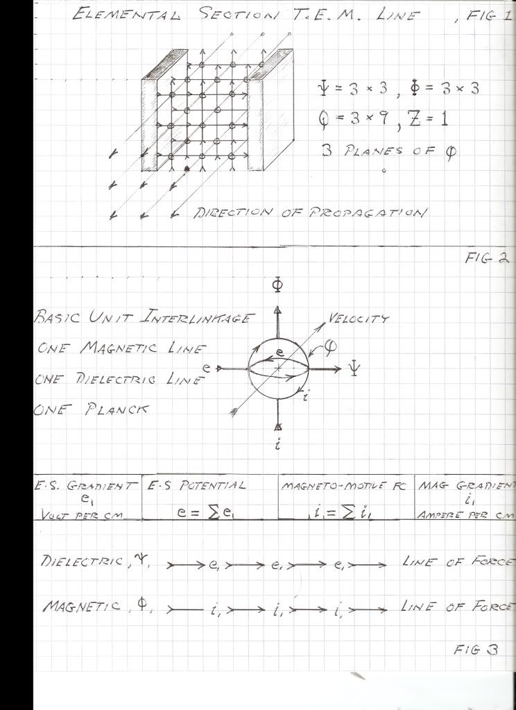
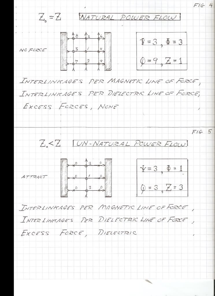
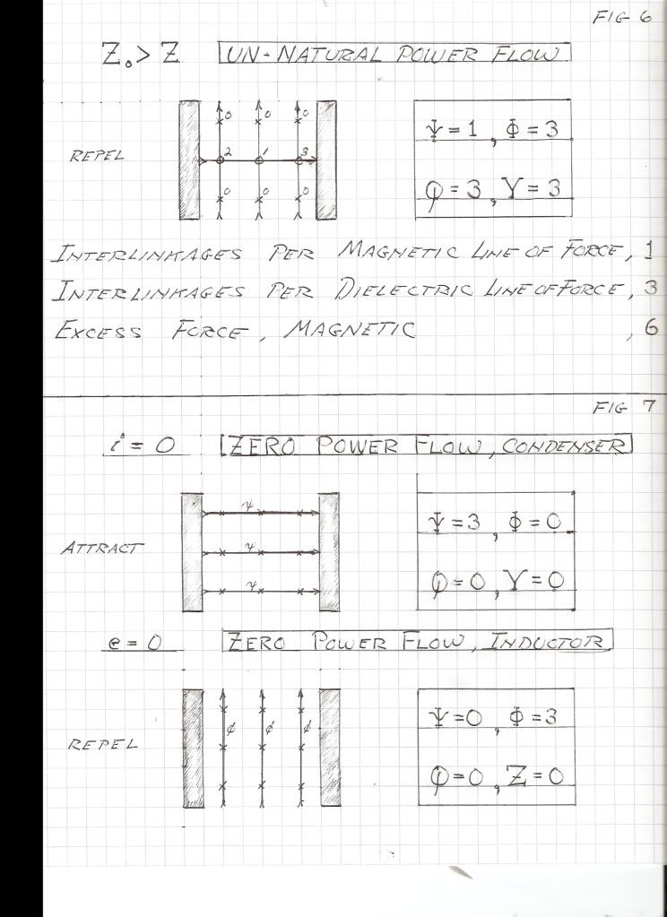
                  Figure 1, an elemental section of a Transverse Electromagnetic Transmission Line. Vertical Lines are Magnetic Lines of Force, and Horizontal Lines are Dielectric Lines of Force. Circles at crossings are Plancks. Note that the Plancks are in planes of Magnetic/Dielectric Lines of Force. Three Planes are shown thus the product of Magnetic and Dielectric Force equaling Q in Plancks is a Planar Process, not a Volumetric Process in this Geometric Representation. Figure 2, this is a symbolic expression of the union of one Magnetic Line with one Dielectric Line. Figure 3 is the gradients in the Lines of Force and their direction of summation into the Electro-static Potential and Magneto-Motive Force. Fig. 4, 5, & 6 represent balanced and unbalanced Power Flow. Figure 7 is the section of the line reduced to a Basic Condenser, or Inductor, and No Propagation is in Effect.

                  73 DE N6KPH


                  SUPPORT ERIC DOLLARD'S WORK AT EPD LABORATORIES, INC.

                  Purchase Eric Dollard's Books & Videos: Eric Dollard Books & Videos
                  Donate by Paypal: Donate to EPD Laboratories

                  Comment


                  • Originals

                    Forces Upon Conductors, and The Planck contains the original images scanned.

                    Comment


                    • Beat Me to It!

                      The above T-rex transmission is a continuation of his prior work Theory of Wireless Power [1986] specifically from pages 34 to 69. If anyone wanted to understand what Mr. Dollard wrote further, reading that portion of the afore mentioned book is highly recommended. Also the reference I listed on my prior post by Mr. Steinmetz is a recommended read to accompany this recent T-rex transmission.

                      It would seem that my prepared post on Natural Impedance and the hair pin circuit seems unnecessary now, I don't think I could follow up after a post like that! I do hope to have the free time to finish my post on the clear headed solution of parametric variation of storage parameters L & C with respect to time t soon. (I don't feel that anyone has posted a good algebraic study and generalized solution to this yet, at least on this forum)

                      I hope everyone reads that post by Mr. Dollard very carefully, there is a mountain of useful information contained within and new terms that have popped up that were in need of consideration (Traveling Wave & Standing Wave) in the study of Tesla apparatus.

                      For a good reference on those new terms:
                      C.P. Steinmetz - Theory & Calculation of Transient Electric Phenomena & Oscillations 3rd Ed, 5th Imp [1920]

                      Section III: Transients in Space
                      Chapter II - Long Distance Transmission Line
                      Chapter III - The Natural Period of the Transmission Line

                      Section IV: Transients in Time & Space
                      Chapter V - Standing Wave
                      Chapter VI - Traveling Wave
                      Chapter VII - Free Oscillation
                      Chapter VIII - Transition Points & the Complex Circuit
                      Chapter X - Reflection & Refraction at Transition Point

                      Garrett M

                      Comment


                      • Originally posted by garrettm4 View Post
                        It would seem that my prepared post on Natural Impedance and the hair pin circuit seems unnecessary now, I don't think I could follow up after a post like that! I do hope to have the free time to finish my post on the clear headed solution of parametric variation of storage parameters L & C with respect to time t soon. (I don't feel that anyone has posted a good algebraic study and generalized solution to this yet, at least on this forum)
                        I was just going to say I'm glad Eric covered how a standing wave operates specifically in respect to the hair pin circuit. Also because the primary of the TMT is fundamentally a hair pin style circuit. I believe understanding standing waves is crucial in figuring out how the hairpin/primary of the TMT interacts with the aether. In the video of the hairpin demo, Karl Palsness made reference to nodes/zones where there appear greater and lesser amounts of energy. (ignore the fact he says scalar waves) It appears creating standing waves is desirable in terms of separating the dielectric from the magnetic. Jeremy has an excellent post discussing this phenomenon here.

                        I am still trying to figure out how this all relates to radiant energy, and how longitudinal waves are created. Garrett I would still be interested in your explanation on Natural Impedance and the hairpin. It's good to have multiple perspectives on the same issue when it comes to understanding this.

                        Also I am wondering doesn't the core of a transformer naturally separate the dielectric & magnetic lines of flux, with the magnetic lines almost being entirely contained within the core material and the dielectric lines mostly existing outside of it?

                        I plan on constructing a hairpin circuit soon. I really want to experiment with these standing waves. Anyone know where I can get a 15,000V DC transformer?
                        A collection of Eric Dollards latest posts and writings on my website: Gestalt Reality - Eric Dollard

                        Comment


                        • Audio analysis - Phase difference confirmed:


                          Left channel is the circuit posted by Eric + flat spiral coil. Right channel is the circuit from "200 In One Electronic Project Lab".
                          http://www.teslascientific.com/

                          "Knowledge is cosmic. It does not evolve or unfold in man. Man unfolds to an awareness of it. He gradually discovers it." - Walter Russell

                          "Once men died for Truth, but now Truth dies at the hands of men." - Manly P. Hall

                          Comment


                          • Originally posted by Gestalt View Post
                            I am still trying to figure out how this all relates to radiant energy, and how longitudinal waves are created. Garrett I would still be interested in your explanation on Natural Impedance and the hairpin. It's good to have multiple perspectives on the same issue when it comes to understanding this.
                            In the most simplistic, man-made form, Longitudinal Waves are a result of an LC oscillation of the TEM transmission. L and C are spatial functions in themselves, but when multiplied, space cancels and you are left with a time function. This is when space becomes scalar. The RAYS of induction are existing equally, everywhere in space, tending towards electrification more-so on the COMPLIMENTARY RESONANT conductor surfaces. This is the basis for no inverse of distance function, propagation without loss of signal strength, longitudinal transmission, etc.

                            Dave
                            Last edited by Web000x; 01-19-2012, 07:32 AM.

                            Comment


                            • Originally posted by dR-Green View Post
                              Audio analysis - Phase difference confirmed:


                              Left channel is the circuit posted by Eric + flat spiral coil. Right channel is the circuit from "200 In One Electronic Project Lab".
                              That is some good looking data. What is your time span on that audio waves? also, how far away from the transmitting tower are you?

                              Dave

                              Comment


                              • New EPD Cosmic Induction Generator Photos

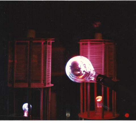
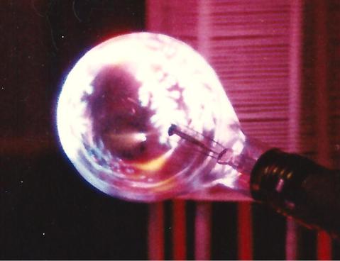
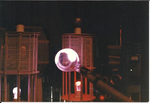
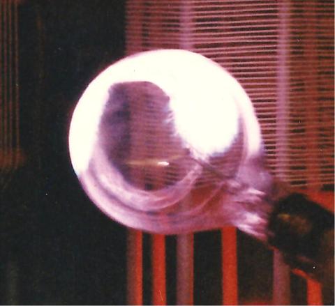
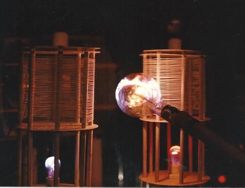
                                Thomas Brown just posted many photos he scanned of Eric's Cosmic Induction Generator, they are on the N6KPH yahoo group http://groups.yahoo.com/group/n6kph/photos/album/0/list

                                I'm posting them here for the benefit of those who haven't joined the yahoo group.

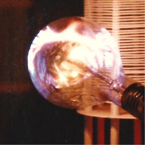
                                **Eric, can you please explain the purpose of the bulbs beneath the 2 extra coils, I believe the bulbs on top are the "top loads" to add capacitance, but don't understand the function of the illuminated bulbs that are below the coils. Also, I'd love to hear any further elaborations you have on what is happening in the bulb where the galactic formation is occurring, such as the explanation of the comet you gave previously. Thanks in advance!**

                                73 DE WX9HV


                                Tom's post:
                                "-- In [email protected], "max.thompson" <alchemy2012@...> wrote:
                                >
                                > I've started two albums in the photo section:
                                >
                                > EPD Santa Barbara Labs - these are plasmas from the Cosmic Induction Generator circa 1987-88. They are numbered, those with an "a" are 600 dpi closeups of the 300 dpi main picture
                                >
                                > Marconi Building Number 1 - these are four pictures of Eric's from pre-Integratron days.
                                >
                                > I have more, putting the better ones first, but will them scanned and posted as able.
                                >
                                > Tom"
                                Attached Files
                                Last edited by Lambda; 01-19-2012, 09:39 AM.

                                Comment

                                Working...
                                X