Announcement

Collapse
No announcement yet.

Peter, whatever happened with Eric P. Dollard?

Collapse
This topic is closed.
X
This is a sticky topic.
X
X
 
  • Filter
  • Time
  • Show
Clear All
new posts

  • RG316 coax cable

    In Eric dollard's video on longitudinal waves, Peter Lindemann says the coax cable used had a diameter about .080". The RG316 coax is .098" dia, while the RG178 coax cable is .071" dia. The other difference is the max attenuation of the two cables. The RG316 has 22.452 dB/100' @ 750MC and the RG178 has 42.7 dB/100' @ 900MC attenuation. But because we use the shield as the conductor I don't think it matters. To measure the weight of the silver coated shield is more difficult for this reason Eric recommended the matching the surface area of coax cable shield secondary to that of copper strip primary. Both RG178 and RG316 can be purchased on Ebay for about the same price. I wonder how much difference does it make that the RG178 core is silver plated, copper clad steel and that of the RG316 core is copper.
    Last edited by Nhopa; 01-22-2012, 09:47 AM. Reason: To add important information left out of the original post

    Comment


    • Eric,

      If by chance you are reading this thread, please give me a call. I will be available to answer my phone Sunday, 1/22, around 5 P.M. EST or before 3 P.M. EST on Monday or Tuesday. I am in touch with somebody that may be of interest to you that would like to get in touch with you ASAP.

      Dave

      Comment


      • Symbolic Rep. of the Gen. Electric Wave by E.D.

        I've been going back and reading more of Eric Dollard's notes. I think I understand the basics of four quadrant electricity, which explains the two types of electricity, steady state and transient phenomena. However, I'm trying to grok the versor math as I think it holds the key to developing an overunity system.

        In the text "Symbolic representation of the generalized electric wave", Eric introduces "k", where a wave = a+kb. Where
        a=non-time dependent power factor
        b=time dependent induction factor

        In addition, Eric states that k denotes that b is time dependent. However, in the paper he rotates the wave backwards by 90 degrees and then states that the wave = ka-b since multiplying by k shifts the wave backwards by 90 degrees. This seems strange since by definition, a is time invariant and k denotes time dependency. Eric's math appears to imply that if you retard a wave by 90 degrees then the power factor is suddenly time dependent. I would think the wave shifted by 90 degrees backwards should be: wave=a-bk

        I know my question is very technical, but I want to understand the theory. Anyone want to take a stab at what I'm missing?

        The link to the paper is at:

        Comment


        • Practical questions

          For me getting metal spheres is difficult. Can I use a plastic ball and glue aluminum foil over it as a substitute for a real metal sphere? Also I can't get copper strip for the primary coil, how would the functioning and size, i.e. the length be effected if I used brass strip instead for the primary? Any help will be appreciated.

          Comment


          • Making Copper Strip

            Originally posted by Nhopa View Post
            For me getting metal spheres is difficult. Can I use a plastic ball and glue aluminum foil over it as a substitute for a real metal sphere? Also I can't get copper strip for the primary coil, how would the functioning and size, i.e. the length be effected if I used brass strip instead for the primary? Any help will be appreciated.
            Hhopa

            It may be a pain to do, but you could take copper plumbing pipe, and split the pipe to make strip. If you have access to a bandsaw, you could make a jig up, consisting of a block with a hole, say 15mm. The block is attached to the saw bench and the blade travels through the block. You would then feed the pipe into the block and it would be in the correct position to split the pipe in half, maybe feed pipe through again to quater it.
            Just a thought.
            Regards
            John

            Comment


            • Okay, so I feel a bit foolish having tried to build circuits emulating Dollards work before reading all of his references and papers. I'm working my way through his work on tesla's oscillating current transformer and I'm wondering if anyone has built a DC tesla coil transformer with the secondary having an n=1 (length to diameter ratio)? It sounds like a short fat secondary is critical to reproduce the unique effects.

              My primary interest is in the production of the dielectric field, not in transmitting, so I'm not sure I need the three coil arrangement. I'm guessing if I balance the secondary and primary with regards to surface area, make the secondary n=1, wrap it on a proper form and drive it properly with a DC capacitive discharge that I may start to see the special effects. Any thoughts from anyone?
              Last edited by skaght; 01-26-2012, 04:54 AM.

              Comment


              • o, 1 Volt

                Short Circuit Current, io, 1 Ampere

                And thus the ratio of one volt to one ampere is

                Natural Impedance, Zo, 1 Ohm

                The Polarity markings for eo and io

                Symbolically it is
                (2)

                With roots, +1 and -1

                The versor operator becomes, for this D.C. condition of bi-directional flow,
                (3)

                And


                ...etc

                Hereby the versor relations of the bi-directional device, such as the unit drycell are given
                (4)


                And it is

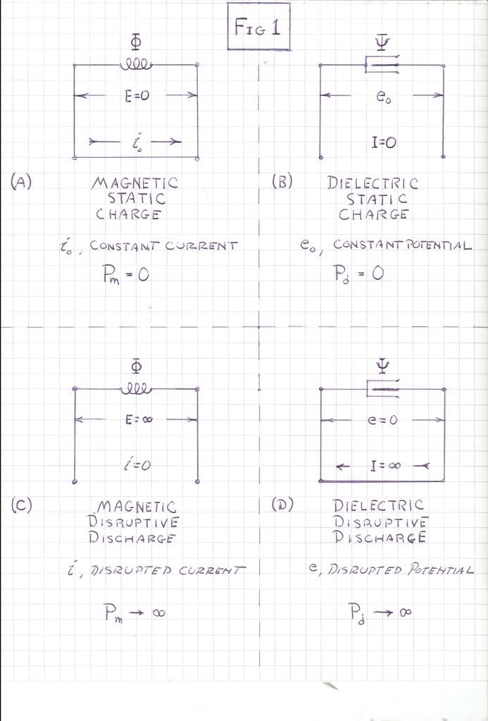
                The energy stored within the Magnetic Field of Induction can be supplied to, or taken from the unit drycell. Likewise the energy stored within the Dielectric Field of Induction can be supplied to or taken from the unit drycell. Whereas the disruptive circuit condition completely open circuits the Inductance, or completely short circuits the Capacitance, here now the unit drycell is inserted in the place of the open circuit, or the short circuit. Circuit Continuity is hereby maintained by the drycell. Energy can now be transferred in a finite manner.
                SUPPORT ERIC DOLLARD'S WORK AT EPD LABORATORIES, INC.

                Purchase Eric Dollard's Books & Videos: Eric Dollard Books & Videos
                Donate by Paypal: Donate to EPD Laboratories

                Comment


                • Four Quadrant Energy Exchange in Magnetic & Dielectric Fields of Induction, Part One:

                  (Continuing in another post due to restrictions)

                  The Magnetic Inductance can take the Chemical Energy out of the drycell, storing it within its magnetic field. Conversely, The Magnetic Inductance can deliver its Stored Energy to the Chemical Energy of the drycell. This is a two way Reciprocal Relation.

                  Likewise, The Dielectric Capacitance can take the Chemical Energy out of the drycell, storing it within its Dielectric Field. Conversely, The Dielectric Capacitance can deliver its Stored Energy to the Chemical Energy of the drycell. Again this is a two way Reciprocal Relation. The Inductance and Capacitance can give or take energy just as can the drycell.

                  Hereby Four Distinct Conditions exist, a pair for each Field of Induction, one pair the Energy Transfer between the Drycell and Inductor, (1) charge, (2) discharge, the second pair the Energy Transfer between the Drycell and Condenser, (3) charge, (4) discharge. Hence,

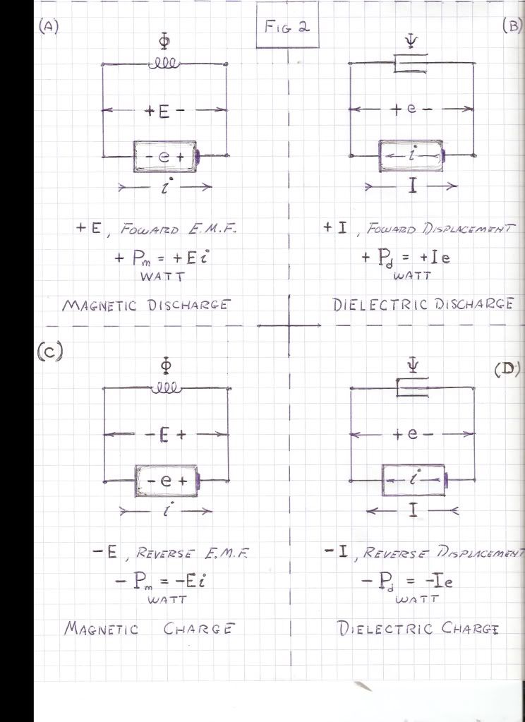
                  (1) The Energy, W, in Joules, stored in the Magnetic Field, Phi, in Weber, is delivered by Electrical Activity, P, in Watts, Fig 2A, to the drycell

                  (2) The Energy, W, in Joules, stored in the Dielectric Field, Psi, in Coulomb, is delivered by Electrical Activity, P, in Watts, Fig 2B, to the drycell.

                  (3) The Energy, W, in Joules, stored in the Magnetic Field, Phi, in Weber is derived from the Electrical Activity, P, in Watts, Fig 2C, out of the Chemical Energy of the drycell.

                  (4) The Energy, W, in Joules, stored by the Dielectric Field, Psi, in Coulomb, is derived from the Electrical Activity, P, in Watts, Fig 2D, out of the drycell.

                  Hence Magnetic Power Flow in watts can transfer energy from the Magnetic Field, or to the Magnetic Field, this energy to, or from, the Chemical Energy of the drycell. The flow of power is two way, or bi-directional. It is a differential quantity.

                  Likewise hence, Dielectric Power Flow in watts can transfer energy from the Dielectric Field, or to the Magnetic Field, this Energy to, or from, the drycell. Again the Power Flow is bi-directional, a differential quantity.

                  The Magnetic Inductance develops an Electro-Motive Force, E, during the Time of Energy Transfer with the drycell. This E.M.F. acts in conjunction with, or in opposition to, the Continuity of Current (M.M.F.), i, this developing the Electrical Activity, Ei, in watts, of Energy Transfer. This Activity, or Power, Pm, is the time rate of Energy Transfer.

                  Likewise, the Dielectric Capacitance develops a Displacement Current, I, during the Time Interval of Energy Transfer with the drycell. This Displacement acts in conjunction with, or in opposition to, the Continuity of Potential, e, this developing the Electrical Activity, Ie, in watts, of Energy Transfer. This Activity, or Power, Pd, is the Time Rate of Energy Transfer.

                  It hereby can be seen that the dimension of Time plays an important role in this Energy Transfer. Electrical Activity is the time rate of Energy Transfer,

                  Watt, or Joule per Second. (5)

                  The longer, more prolonged, time rate of transfer, the less in magnitude is the Power Flow. Likewise, the shorter, more instantaneous, time rate of transfer, the greater in magnitude is the Power Flow. The Disruptive Discharge is a Limiting Condition, and as well is the Static Charge. In both cases the Flow of Power is zero. The Energy remains within the Inductor or the Condenser.

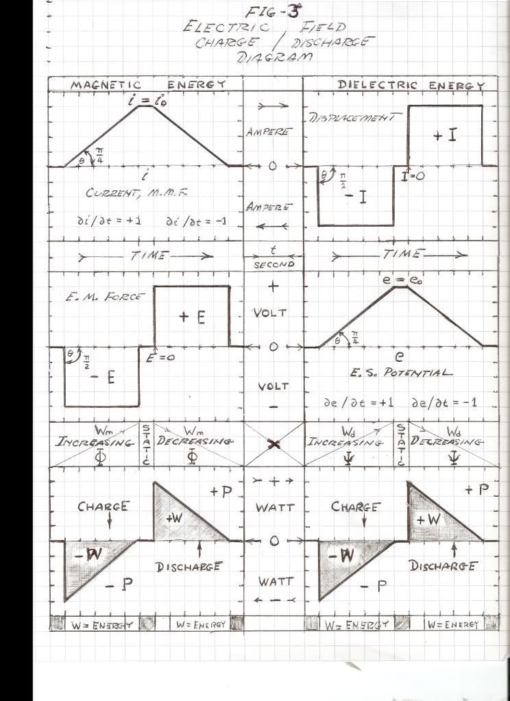
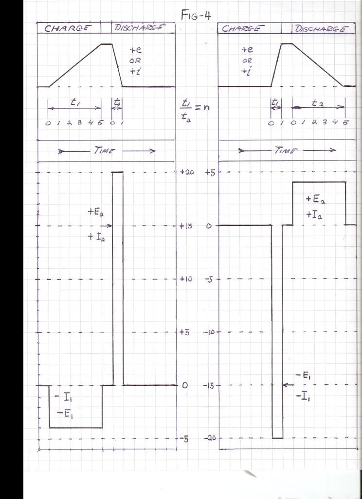
                  Thru adjustment of the time rate of charge, and the time rate of discharge, involved in Energy Transfer into, or out of, a Field of Induction, any magnitude of Electrical Activity, P, can be developed from a given quantity of stored Energy, W, Fig 3, Fig 4. Denoting the charge time as t1, and the discharge time as t2, taking the ratio as,
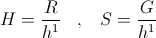
                  , Numeric (6)

                  The Power Magnification is given as
                  , Watts, (7)

                  And thru Energy Conservation, it is,
                  , Joules (8)
                  ,


                  ,
                  SUPPORT ERIC DOLLARD'S WORK AT EPD LABORATORIES, INC.

                  Purchase Eric Dollard's Books & Videos: Eric Dollard Books & Videos
                  Donate by Paypal: Donate to EPD Laboratories

                  Comment


                  • Four Quadrant Energy Exchange in Magnetic & Dielectric Fields of Induction, Part One:

                    (Continuing in another post due to restrictions)

                    Where is the charge/discharge versor operator. Substituting these expressions into the general relations of Power Flow, the magnetic,

                    (12)
                    ,


                    ,

                    And, the dielectric,

                    (13)
                    ,


                    ,

                    Hence the most general expression for Versor Power is,

                    (14)
                    , Versor Watts

                    , Versor Watts

                    Where, N = 0,1.

                    Break, more to follow.


                    SUPPORT ERIC DOLLARD'S WORK AT EPD LABORATORIES, INC.

                    Purchase Eric Dollard's Books & Videos: Eric Dollard Books & Videos
                    Donate by Paypal: Donate to EPD Laboratories

                    Comment


                    • Four Quadrant Energy Exchange

                      Thank you Eric, this is a wonderful summary. Looking at Figure 4, it seems to me the dielectric charge/discharge cycle allows a kind of "pumping", that is with a properly designed system to provide an almost uniform output from the extra coil, since the charge/discharge time ratio is 1:5 respectively, versus the magnetic charge/discharge time ratio of 5:1 respectively. Is it not what Tesla tried to accomplish?

                      Comment


                      • Coil design

                        Originally posted by skaght View Post
                        Okay, so I feel a bit foolish having tried to build circuits emulating Dollards work before reading all of his references and papers. I'm working my way through his work on tesla's oscillating current transformer and I'm wondering if anyone has built a DC tesla coil transformer with the secondary having an n=1 (length to diameter ratio)? It sounds like a short fat secondary is critical to reproduce the unique effects.

                        My primary interest is in the production of the dielectric field, not in transmitting, so I'm not sure I need the three coil arrangement. I'm guessing if I balance the secondary and primary with regards to surface area, make the secondary n=1, wrap it on a proper form and drive it properly with a DC capacitive discharge that I may start to see the special effects. Any thoughts from anyone?
                        The following discussion will reference Nikola Tesla's Colorado Springs Notes 1899-1900, from now on just called the Notes. So far I have not seen any reference in the Notes that the secondary coil should be n=1, that is diameter to lenght ratio of 1. All the secondary coils described in the Notes are much longer than their diameter. On the other hand the so called "extra" or Tesla coils are closer to that 1:1 ratio, as can be seen from some of the photographs in the Notes. With the "extra" coil Tesla has achived extremely high e.m.f.. I think the extra coil is necessary for the reproduction of unique effects. Although, you are not interested in transmitting/receiving but to best achieve it Tesla prefers the use of "flat spiral form of coil...", page 66 of the Notes. Teasla indicates in a couple of places in the Notes that the copper masses in the primary and secondary should be equal, for example page 193. On the other hand in Eric Dollard's book "Condensed Intro to Tesla Transformers", page 16, Eric is recommending the use of equal surface area rather than weight because of the skin effect. Eric also used the surface area method in costructing his transmitter/receiver antennas used in his Longitudinal Waves demonstration video. In my coil calculations I equated the weight of primary to the secondary coil as Tesla did then when I compared the surface areas, my secondary has 18.8% more surface than my primary flat copper strip coil. I am sure the calculation can be set up so to find a good close compromise between surfaces and weights.

                        Comment


                        • Practical questions con't

                          1. In my design the weight of primary coil is the same as the secondary coil. Should the primary coil be one turn copper strip or two? I can make the strip half wide and twice the length. Does it matters? Looking the surface areas the secondary coil has 18.8% more surface area than the primarycoil.
                          2. I have an unused dug well on the property with some water in it. Would it function as an acceptable ground if I would lower into the water a heavy cable with some metal weight on the end?
                          3. Will a tennis ball covered with aluminum foil work as a spherical metal capacitor?
                          4. The radio station for which I am designing the crystal receiver is transmitting @ 1,476 Kc/sec with 60KW power. I am located 110 miles from it, am I too far from this station?
                          5. Is it important which direction the "extra" coil is wound with respect to the secondary coil? Secondary coil is wound in the same direction as the primary coil.
                          6. In order to make the spiral coil a smaller diameter, would it make much difference if I wound 3 turns on top of each other in each groove instead of the two as Eric has done it for the Longitudinal Wave demonstration video?
                          Thank you in advance for any suggestion or recommendation.

                          Comment


                          • Originally posted by Nhopa View Post
                            So far I have not seen any reference in the Notes that the secondary coil should be n=1, that is diameter to lenght ratio of 1. All the secondary coils described in the Notes are much longer than their diameter.
                            I think you will find that it's the diameter of the secondary that's much greater than its height/length (15 metres diameter x about 2m high) The extra coil is equal diameter to height ratio.

                            Also I read somewhere in the CS Notes, a greater surface area of secondary will result in a greater pressure than an equal number of turns with thinner wire. I think, I didn't make a note of what page it was so I can't easily find it again. That reference MIGHT be somewhere around page 60.

                            @skaght: In my opinion you are probably complicating it through trying to simplify it. Beware the illusion of something becoming simpler through removing parts - reality is one continuous whole, not a collection of parts. That is, Eric wants people to do it "properly" and is answering things on that basis, so you won't get a simple answer. If you just build it then you won't need to ask the question
                            http://www.teslascientific.com/

                            "Knowledge is cosmic. It does not evolve or unfold in man. Man unfolds to an awareness of it. He gradually discovers it." - Walter Russell

                            "Once men died for Truth, but now Truth dies at the hands of men." - Manly P. Hall

                            Comment


                            • Originally posted by Nhopa View Post
                              1. In my design the weight of primary coil is the same as the secondary coil. Should the primary coil be one turn copper strip or two? I can make the strip half wide and twice the length. Does it matters? Looking the surface areas the secondary coil has 18.8% more surface area than the primarycoil.
                              2. I have an unused dug well on the property with some water in it. Would it function as an acceptable ground if I would lower into the water a heavy cable with some metal weight on the end?
                              3. Will a tennis ball covered with aluminum foil work as a spherical metal capacitor?
                              4. The radio station for which I am designing the crystal receiver is transmitting @ 1,476 Kc/sec with 60KW power. I am located 110 miles from it, am I too far from this station?
                              5. Is it important which direction the "extra" coil is wound with respect to the secondary coil? Secondary coil is wound in the same direction as the primary coil.
                              6. In order to make the spiral coil a smaller diameter, would it make much difference if I wound 3 turns on top of each other in each groove instead of the two as Eric has done it for the Longitudinal Wave demonstration video?
                              Thank you in advance for any suggestion or recommendation.
                              This is my opinion

                              1. Two. Best to keep it in accordance with the patent and Eric's design to start with.

                              2. I don't know, but I'm inclined to think that won't be up to some people's standards. Although it may still work.

                              3. Yes a tennis ball will work, but probably not very well due to being small and low capacitance. You might be able to overcome this with the use of the metal plate near it.

                              4. You'll probably hear the radio, but in relation with question 2 you probably won't be lighting up a 100 watt bulb any time soon

                              5. Extra coil should be wound in the same direction. I don't think this is required with a flat spiral coil.

                              6. Read from page 120 of the CS Notes. I believe the purpose of the layered turns is to set up series capacitance in order to overcome the undesirable parallel capacitance that's a result of the spaced turns. Or something to that effect. You can try 3 but I don't think anyone knows the answer as to whether it will be better or worse, unless the posted equations can predict it or someone has actually done it and seen the differences for themselves.
                              Last edited by dR-Green; 01-28-2012, 12:24 AM.
                              http://www.teslascientific.com/

                              "Knowledge is cosmic. It does not evolve or unfold in man. Man unfolds to an awareness of it. He gradually discovers it." - Walter Russell

                              "Once men died for Truth, but now Truth dies at the hands of men." - Manly P. Hall

                              Comment


                              • I thought it was an avalanche through a lump transmission line into a thyratron tube giving a longitudinal asymptotic pulse.

                                This seems aggressive yet very smooth compared to the erratic transverse kW sized sparks that I keep seeing on this thread.

                                What would be wrong with an Lwave of 80 volts 50mA on 160M ?

                                Comment

                                Working...
                                X