Hello Sputins,
Thanks for your fast response.
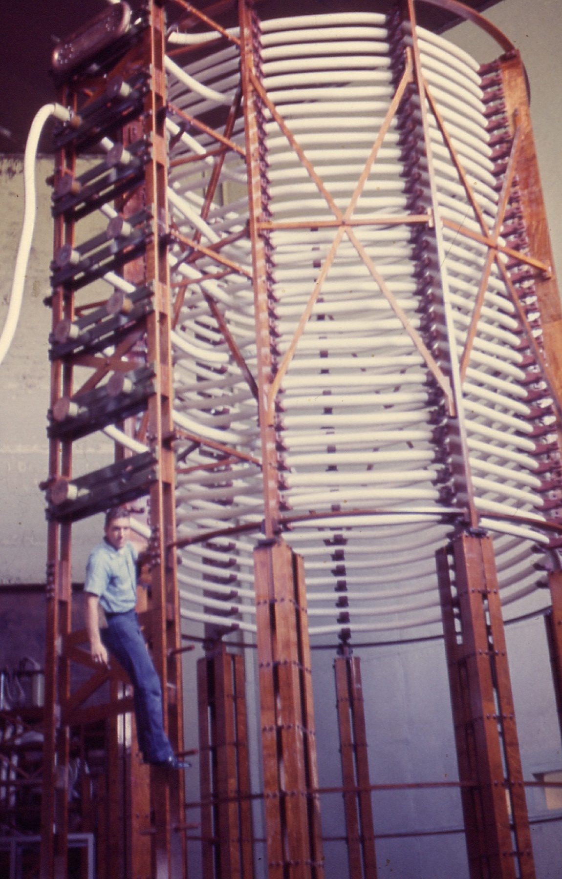
I see on the pictures that Tesla coils are usually built in according to H>>D, where H - height, D - diameter. What could you advice?
I am going to build a coil where the wire length is 3.75m, it means that
1/4 lambda is 3.75m (lambda = 15m, Freq = 20MHz) What diameter and the height of the coil should be chosen in a proper way? What could you advice?
Alex
Announcement
Collapse
No announcement yet.
Eric Dollard
Collapse
This is a sticky topic.
X
X
-
Phi?
Originally posted by Alexg800 View PostHello Raui,
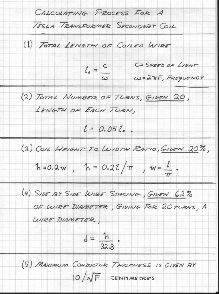
You have showed the calculation of the secondary of Tesla transformer.
I only would like to ask you of the "GEVEN" 20% ratio H/W
(height/diameter of the coil). Please, could you explain why 20% ? Where from this ratio? What will be if to use a GOLDEN RATIO = 1.618?
Leave a comment:
-
Hello Raui,Originally posted by Raui View PostDoc,
The 4.8*10^9 / F comes from the simplification of;

Since;

We can say that;

Or at least very close to.
The reference to the first equation comes from;

In the figures Eric gave you you'll see that the extra coil wire length is smaller than quater wave at luminal velocity. The way I think about it however is if you have more meters covered per second and your frequency in per seconds stays the same, which it does since we know the specific frequency we're tuning for, the wavelength will naturally have to be longer not shorter. Here's another way to think about it get your hands and move them a certain distance apart in one second and take a quarter of that distance. Now compare it to moving them further apart than the first time and take a quarter of that, assuming it was covered in the same time the distance is longer and not shorter than the original since the time is the same. At least that's how I'm seeing it
No problem about the books, Garrett was the one that pointed me in the direction of a digital copy of Introduction to Circuit Theory and I found Theory of Linear Physical Systems while I was on the same website (Hathi-trust) so he is to thank for it as well. The only thing I did was 'extract' the images from the digital library and combined them into a pdf
EDIT: Btw just a quick update on the SEC/Extra coil experiment, I want to make sure that I reduce the number of variables I'm dealing with so I'm having to make a coil form for each coil. I don't have the right drill bit I need. Dad said he'd pick me one up from the hardware store of the way home so hopefully tonight I'll be able to start winding the coils.
Also, Aaron this isn't my forum and I truly mean no disrespect but I'm finding it really frustrating having to navigate through 3 topics instead of one. I don't know if anyone else is in the same boat but I'd like to see all 3 topics merged into one. I know that you're trying to stop posts getting deleted but when posts are getting deleted it's the authors of those posts who are deleting them. Also why is it that it's only this topic which is getting continuation topics while the others which have just as many people posting, if not more, aren't?
Raui
You have showed the calculation of the secondary of Tesla transformer.
I only would like to ask you of the "GEVEN" 20% ratio H/W
(height/diameter of the coil). Please, could you explain why 20% ? Where from this ratio? What will be if to use a GOLDEN RATIO = 1.618?
Leave a comment:
-
Eric Dollard LIVE Call
Live Eric Dollard call - starting in 24 minutes: Conference Dial-in: 1-857-232-0155, Conference Code: 582590 - starting at 11AM pacific daylight savings time - not pacific standard time.
@David - I asked your question on the live call last time. Will be posting a YouTube video of that call sometime today.
Leave a comment:
-
I see. Tesla coils don't have resonant frequency lower than the lowest fundamental one. They do have frequency of beats corresponding to the free response of 2 coupled circuits. Of course, they also have higher resonant frequencies becouse of the distributed nature of the secondary circuit.Originally posted by dR-Green View PostI wasn't referring to Tesla coils, but music. But in basic terms it's the opposite of overtones. It's harmonic frequencies which are below the fundamental frequency, rather than above it. A cymbal for example can produce undertones, because the initial crash can have a certain (high) pitch and a broad range of frequencies somewhat similar to white noise, but a heavy cymbal continues to resonate at a frequency which may be below the initial crash pitch and that continues to ring after the high frequencies have faded.
Leave a comment:
-
question for Eric
Hi Dave,
Eric won't be able to see these but I'll see if I can ask him on the call.
Originally posted by David G Dawson View PostEric Dollard Live Forum:
A question for Eric:
What would be the best application for your 2C22 'Regenerative Magnifying Receiver' (RMR) to be used for - picture attached?
Was this intended as a receiver for the 'Crystal Set Initiative' (CSI) and how was it to be applied and over what distance as an example?
What was the input required or was it just the Telluric Radio Station signal that was to be detected/received?

I also built your 6SN7GT CRI/CSI (Crystal Radio Initiative) Triode Driver.
This has lead to the building of 4 x 6BQ7 amplifier/drivers for use with an Implosion project I am currently working on.
NO solid state allowed.
I am attempting to get back to all of this but have too many projects currently in the build state.
By the way the Lester Hendershot device did NOT work but have intuitions that may help in resurrecting this device when time permits.

My CSI is still working as is the Cosmic Ray Detector (CRD) and have attached some pictures for reference.
Thankyou.
Smokey
Leave a comment:
-
Eric Dollard Live Forum
Eric Dollard Live Forum:
A question for Eric:
What would be the best application for your 2C22 'Regenerative Magnifying Receiver' (RMR) to be used for - picture attached?
Was this intended as a receiver for the 'Crystal Set Initiative' (CSI) and how was it to be applied and over what distance as an example?
What was the input required or was it just the Telluric Radio Station signal that was to be detected/received?

I also built your 6SN7GT CRI/CSI (Crystal Radio Initiative) Triode Driver.
This has lead to the building of 4 x 6BQ7 amplifier/drivers for use with an Implosion project I am currently working on.
NO solid state allowed.
I am attempting to get back to all of this but have too many projects currently in the build state.
By the way the Lester Hendershot device did NOT work but have intuitions that may help in resurrecting this device when time permits.

My CSI is still working as is the Cosmic Ray Detector (CRD) and have attached some pictures for reference.
Thankyou.
Smokey
Leave a comment:
-
I wasn't referring to Tesla coils, but music. But in basic terms it's the opposite of overtones. It's harmonic frequencies which are below the fundamental frequency, rather than above it. A cymbal for example can produce undertones, because the initial crash can have a certain (high) pitch and a broad range of frequencies somewhat similar to white noise, but a heavy cymbal continues to resonate at a frequency which may be below the initial crash pitch and that continues to ring after the high frequencies have faded.Originally posted by Risbo View PostHi!
Will you be kind and explain what do you mean by term"undertones" in the context of Tesla Coil structures?
Leave a comment:
-
Eric Dollard Live Call Tomorrow
If you have any questions for Eric, we have a live call tomorrow:
This coming Sunday the 27th at 11AM Pacific Daylight Savings Time
Leave a comment:
-
Hi!Will you be kind and explain what do you mean by term"undertones" in the context of Tesla Coil structures?Originally posted by dR-Green View PostThere are such things as "undertones" although acoustic instruments don't naturally tend to produce them.
The table doesn't show what happens at higher frequencies. Is there no resonant peak above the fundamental?
[edit] But again, harmonics in this context usually refer to harmonic frequencies produced by something oscillating, as in a harmonic spectrum of an oscillating string at a fixed frequency. Resonant peaks are different. Is this a harmonic spectrum, or a graph of the resonant peaks after doing a frequency sweep? I notice Eric refers to them as a "resonant series" in the diagram and not "harmonics", suggesting it's a series of resonant peaks found when doing a frequency sweep.
Leave a comment:
-
Plasma Globes vs Tesla Bulbs
Yes that was me. I realized I had a dozen more questions about an hour later, so I am going to have to write him a letter (the old school way). I am sorry to hear about your health issues. I hope they work themselves out. You may want to try constructing this and using it as an elevated capacitance: Construction details for the Life Field Transformer device
It outputs a leftward spinning circularly polarized wave which is healing to all biological systems. I have been testing it on dying plants and it seems legit. One of my plants made a full recovery very quickly after looking like it was going to die.
As for the Plasma globe, I realize that it is not an ideal or legitimate replication of Tesla's bulb. In my plasma globe I replaced the swarf with a copper ball. However, isn't carbon a dielectric? I was confused by Tesla's description because how can you connect carbon to the terminal of a coil and have it act inductively on plasma if it is non conductive?
I figured that the conductive terminal must therefore be covered by the carbon inside the bulb. If that is the case, then the plasma globe is not too different from his style of bulb. The plasma globe does appear to add a large capacitance even though the plasma is not directly connected to the coil (dielectric discharge in the plasma).
Leave a comment:
-
Originally posted by Ajay View PostI saw evidence that my assertion (quoted above) was correct in this link:
Flat Spiral Secondary and Longitudinal Waves Experiment - Plasma Balls and Conclusion
If you have not been to this guy's page, I recommend checking him out. This article was specifically interesting because he is using a schematic nearly identical to mine, and he is operating a plasma globe with it just as I did. As you can see, the plasma he produced with his spiral wound secondary was very different from mine. In one picture it even appears brilliantly neon green and white uniformly throughout the globe. Obviously that doesn't happen in ordinary plasma globes.
This is a simple experiment is significant in Tesla research because Tesla often spoke about how his single terminal globes where the ideal terminal capacitance in some respects (greater capacitance than surface area).
The globe is also a homemade superluminal particle accelerator (and collider) according to Tesla's theory of how his single terminal light bulbs worked. Not bad for a $30 home experiment. I hope that more people attempt this experiment so we can catalog the plasma effects (i.e publish the pictures).
Leave a comment:


Leave a comment: