Announcement

Collapse
No announcement yet.

Eric P. Dollard

Collapse
This topic is closed.
X
This is a sticky topic.
X
X
 
  • Filter
  • Time
  • Show
Clear All
new posts

  • jake
    replied
    Originally posted by thugugly View Post
    T-Rex

    Ufopolitics has given us a gift, he, as well as other people, have videod a green color, which is only visable on frame review, which then visable becomes purple, then Orange then normal light as the frequency is adjusted up into low khz, not even that high.

    The neons are being lit on the cold side of diodes, where they should not light.

    This is the radiant field being drawn into the circuit.

    Check out the thread

    "My motors got me tapped into radiant energy"

    Thug
    The green discharges also show up in "Gray Tube" and plasma spark experiments. And is not copper related.

    I've been working with discharges for a while now. I ran into a road block when I could not find an affordable diode capable of withstanding the 1000A+ surge current and blocking 12kV. And it needs to be pretty fast as well.

    Leave a comment:


  • thugugly
    replied
    green and purple color

    T-Rex

    Ufopolitics has given us a gift, he, as well as other people, have videod a green color, which is only visable on frame review, which then visable becomes purple, then Orange then normal light as the frequency is adjusted up into low khz, not even that high.

    The neons are being lit on the cold side of diodes, where they should not light.

    This is the radiant field being drawn into the circuit.

    Check out the thread

    "My motors got me tapped into radiant energy"

    Thug

    Leave a comment:


  • t-rex
    replied
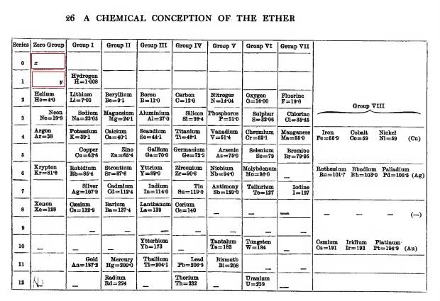
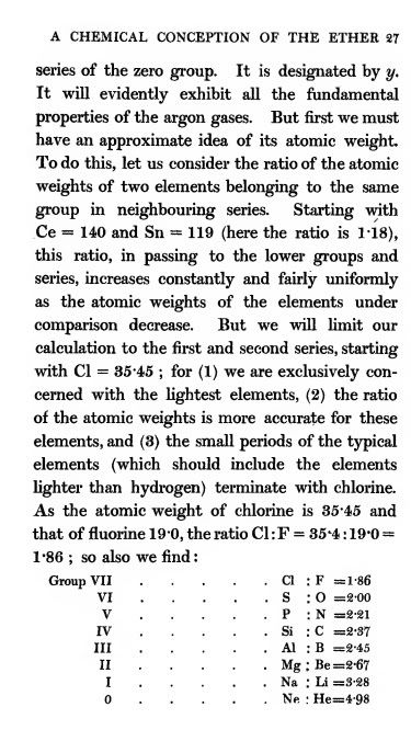
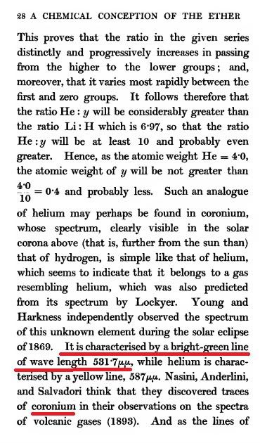
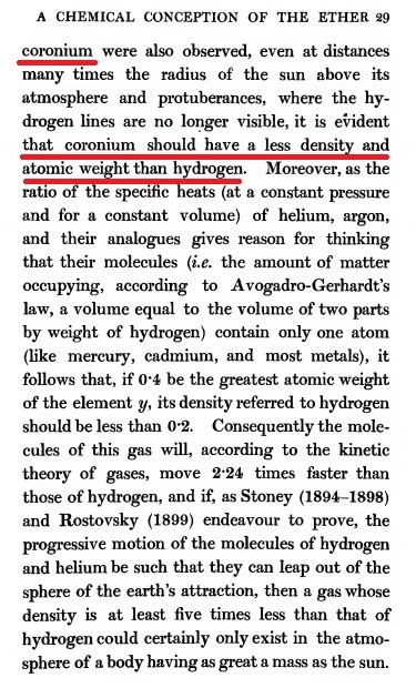
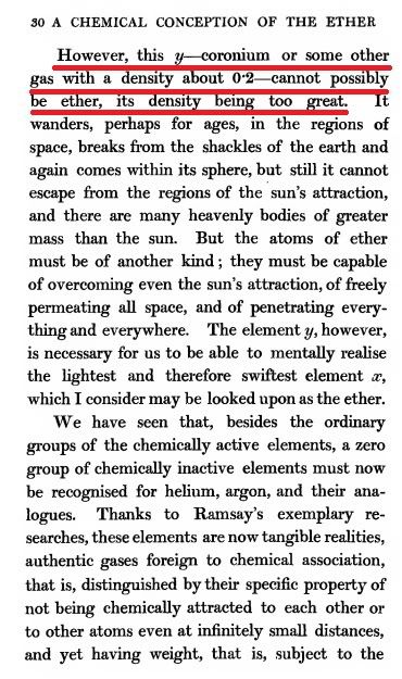
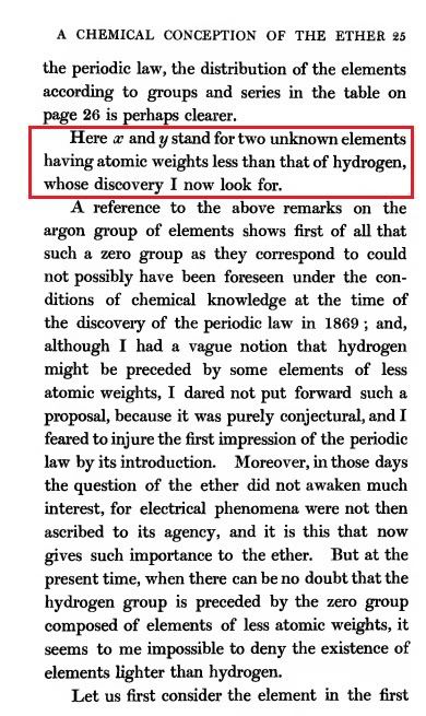
    Mendelev Pre Hydrogen

    The following is from "A Chemical Conception of the Ether", by Mendelev:


    Leave a comment:


  • t-rex
    replied
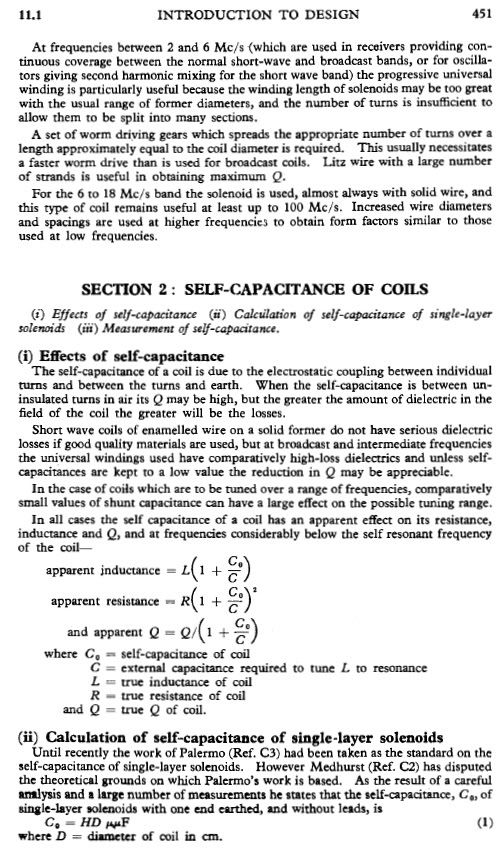
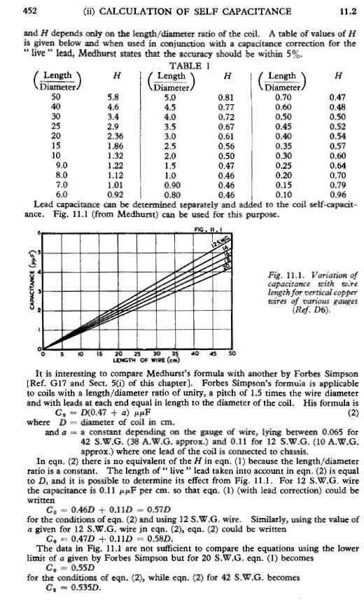
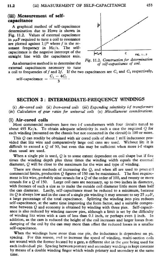
    Someone needs to make a spectral image of their neon bulb to see where the spectral lines are, to see what gasses are in the bulb. Also look at Mendelev Pre-Hydrogen Gas Coronium(corona of the sun) and its spectral lines. Its color is a living green, like spring leaves. It is talked about in the E.P. Thompson book.


    Leave a comment:


  • t-rex
    replied
    From Radiotron Designers Handbook


    Leave a comment:


  • dR-Green
    replied
    Simple DIY adjustable condenser made from 16x16cm and 15x15cm MDF squares, double sided tape, tinfoil and pine dowels, adjustable up to 14.5cm gap:


    Works simply by sliding the 15x15cm plate which is suspended on the dowels, the extending handle also keeping the plates parallel. The plates could be a bit smaller or the gap a little bit bigger as 14.5cm isn't really enough to get the effect down to zero.

    Leave a comment:


  • t-rex
    replied
    Originally posted by Nhopa View Post
    The secondary coil is 20 turns designed for 1,188 Kc.
    Coil is 62 cm dia., wire used is about #17 AWG, .048" dia., coil height 6 cm. I have about 4 cm between the top of primary and the bottom of the secondary, since the instrument's impedance is 50 Ohms I will use a 1 turn test coil. Wire used for the test coil is #17 AWG, .045" dia insulated? The primary coil was removed prior to testing. Please note that using the ground connection did not make any difference in the readings.
    Test data:
    I. Test coil adjacent to bottom of secondary coil.
    1.Can 10 cm above top of secondary coil and 0 cm above 1/4" dia top
    ring.
    a) Function Generator (FG) ground connected to one end of test coil
    and field intensity meter ground: First meter movement at 0 Kc
    Second meter movement at 1,700 Kc
    b) FG ground not connected: First meter movement 402 Kc
    Second meter movement at 1,689 Kc
    2. Can 30 cm above top of secondary coil and 20 cm above 1/4" dia top
    ring.
    a) FG ground connected to one end of test coil and field intensity meter
    ground: First meter movement at 0 Kc
    Second meter movement at 1,687 Kc
    II. Test coil 3 cm below bottom of secondary coil.
    1. Can 10 cm above top of secondary coil and 0 cm above 1/4" dia top
    ring.
    a) FG ground connected to one end of test coil and field intensity meter
    ground: First meter movement at 0 Kc
    Second meter movement at 1,758 Kc
    b) FG ground not connected: First meter movement 431 Kc
    Second meter movement at 1,757 Kc
    2. Can 30 cm above top of secondary coil and 20 cm above 1/4" dia top
    ring.
    a) FG ground connected to one end of test coil and field intensity meter
    ground: First meter movement at 0 Kc
    Second meter movement at 1,763 Kc
    b) FG ground not connected: First meter movement 434 Kc
    Second meter movement at 1,760 Kc
    III. Test coil 8.5 cm below bottom of secondary coil.
    1. Can 10 cm above top of secondary coil and 0 cm above 1/4" dia top
    ring.
    a) FG ground connected to one end of test coil and field intensity meter
    ground: No meter movement at all.
    b) FG ground not connected: First meter movement 416 Kc
    Second meter does not move, but stays
    constantly about at 1 uA reading. It
    appears the movement would start above
    2Mc (out of range)
    2. Can 30 cm above top of secondary coil and 20 cm above 1/4" dia top
    ring.
    a) FG ground connected to one end of test coil and field intensity meter
    ground: No meter movement at all.
    b) FG ground not connected: First meter movement 432 Kc
    Second meter movement. See comment
    above.
    Next I will calculate coil frequencies, but I need to know what to do with the number "4" in Eric's equation no. 8.
    The data you provided is not really understandable. You need to at least provide some kind of diagram, it should be done with the test seyup that I showed. All the neutrals have to be connected to ground, they can't be floating, otherwise you will get all kinds of stray readings. Finally, the secondary is made to be operated with a large external tuning condenser such as 2 six inch disks with variable spacing, or a large transmitting neutralizing condenser. Need to draw frequency response curves around the resonant frequencies of the coils. Bare wire on wood is not such a good idea either, it really increases the losses. The secondary wire is also too small, but ok for testing purposes.

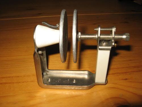
    Neutralizing Condenser:

    Leave a comment:


  • jake
    replied
    Originally posted by T-rex View Post
    Transmission of radio frequency energy for any purpose is subject to government approval, no way around it. Remember that the excuse Franklin Roosevelt, USN used to outlaw radio was the mess of jamming and interference created by electrical experimenters leading up to 1917, the day that wireless died. This can happen again in the 911 police reality, watch out.

    73 DE N6KPH
    So don't use RF. FCC has no say if it ain't RF. RF is for learning. The real magic lies outside RF. Its hard to regulate something they say does not exist.

    Besides lots of people learning here are not in the US so what is the FCC gonna do about that. Go to war with Mexico.

    Believe it or not this is still a free country! There are enough guns in Texas to cause a hurting to the MAN if he tries to pull that poop. People will only take so much...... Shiva wont be able to build her islands if the US goes third world. If we go down the world takes a hurting. That's why we are still here. We should have gone third world by now. But the world keeps taking our..... and tax payers keep footing the bill.

    IF we actually posed a threat do you think we would be talking right now... The MAN knows where I/you live. Is he waiting for me to post "the secret"... before I suddenly have a heart attack.

    viva la revolution.

    End Rant.


    sorry,

    peace love and revolution.

    And I do believe in a free energy. Life have been using it for millions of years. Just because we have not figured out how to use it does not mean we will not one day. We have only been at this for 100 years. And we still cant figure out why things fall.

    NOW END RANT

    Leave a comment:


  • t-rex
    replied
    Comment and Correction

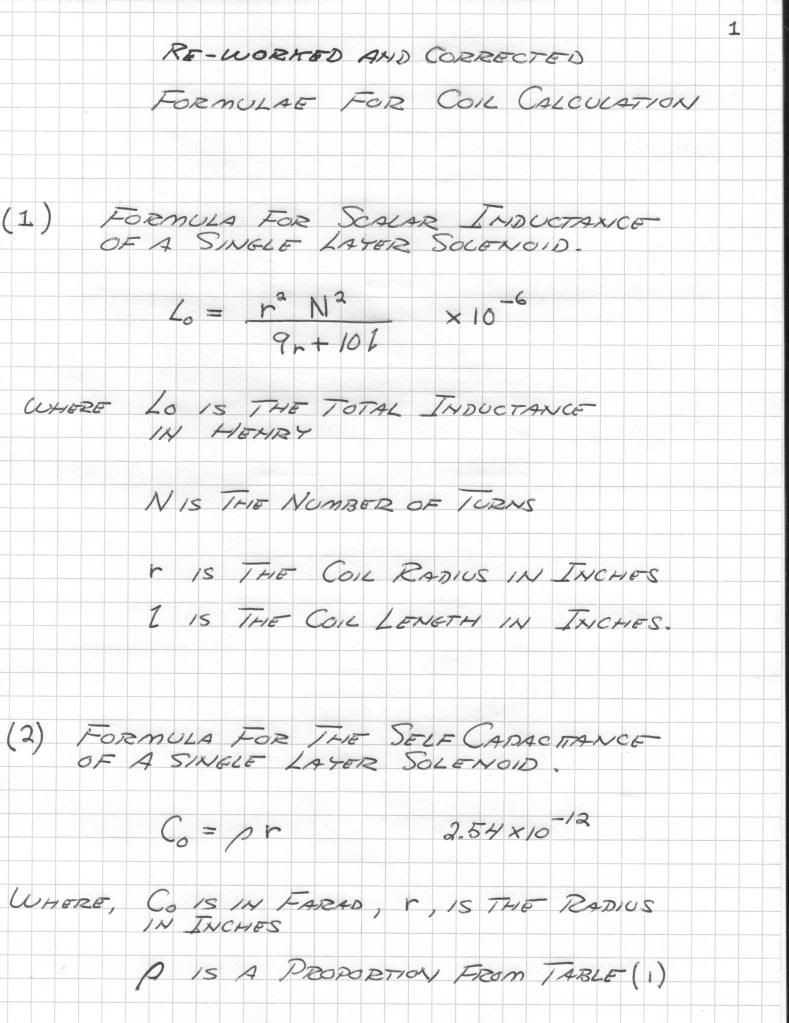
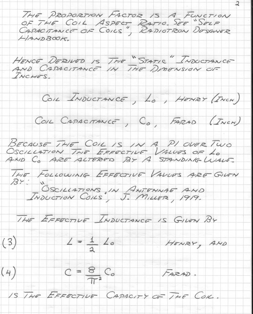
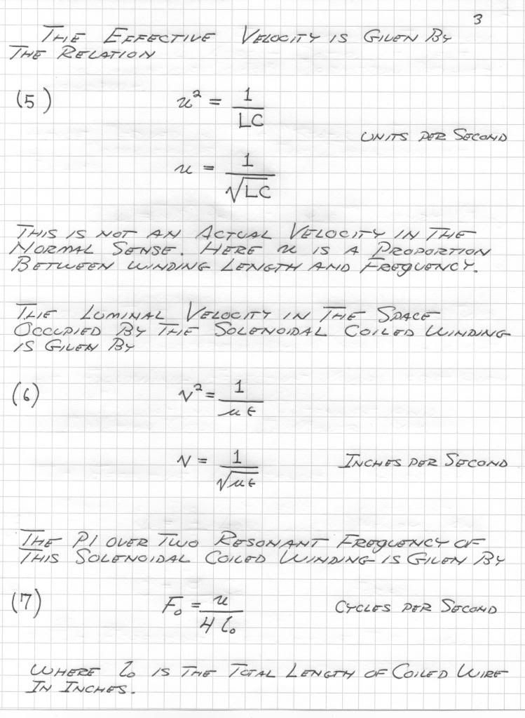
    The following is the corrected version of the equations given in post #404.

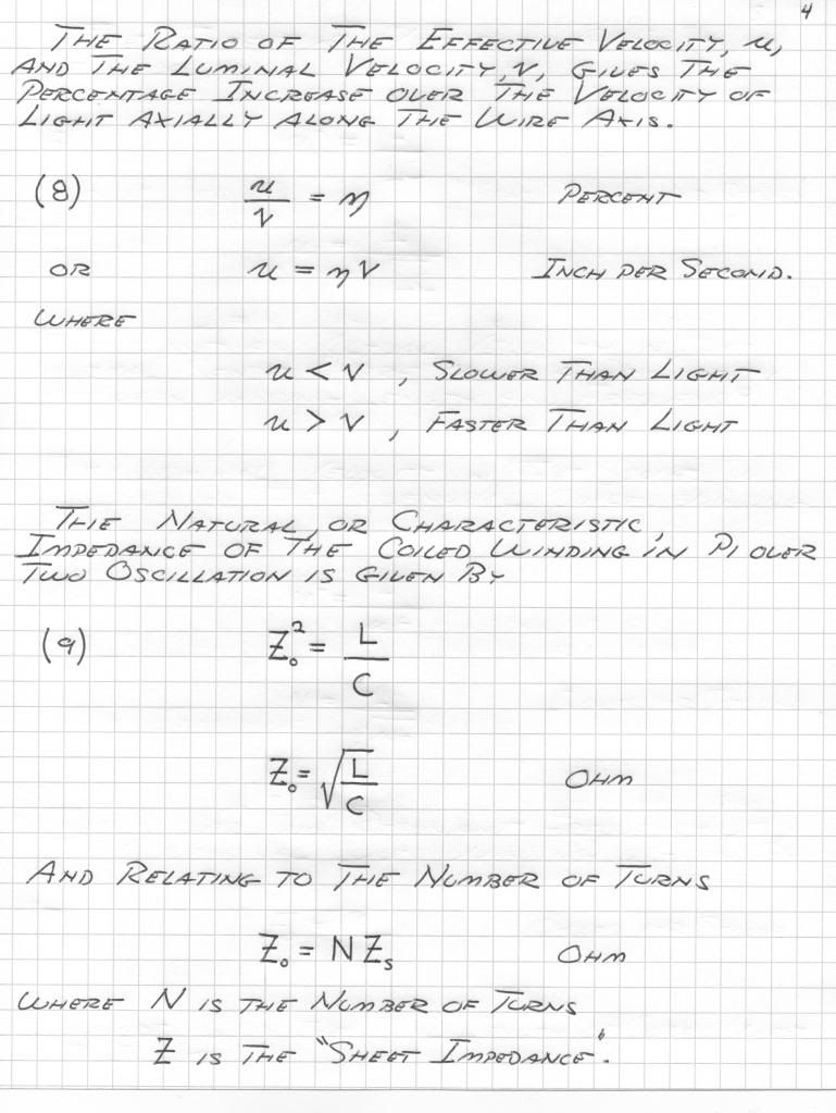
    Equations (1) and (2) still need to be substituted into equations (6), (7), and (9). Graphs should be made up also. Can someone do this and also reprint in better form the following equations. Next, taking the data from the COlorado notes, these equations should be applied to the final Colorado design, here for all to see, u, Z, etc.

    Also the Guillemen line is IMPORTANT, the rest of the MIT pages on it would be helpful here. The Guillemen line is a "single wire" longitudinal transmission structure. Hence it is an analog of a longitudinal wave, or a section of a one wire transmission system. This is known as a "two terminal" network, in distinction to the standard "four terminal" network. Guillemen's rearrangement of the condensers from shunt to series greatly reduced the dielectric stress on these condenser. This allowed for a great reduction of size and weight, important for aircraft. The smallest thermionic gas thyratron suitable for impulse work is the 2050. It is an argon type so not very fast. The smallest hydrogen thyratron is the 3C45. It likes about 1500 volts DC.

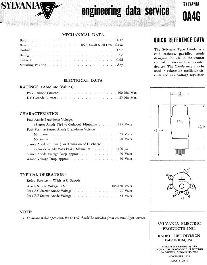
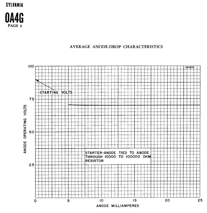
    As for gas diode tubes of the cold cathodes DC type is the,

    OA3, 75 volt neon
    OB3, 90 volt argon
    OD3, 150 volt helium

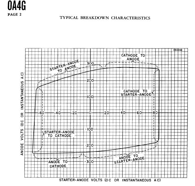
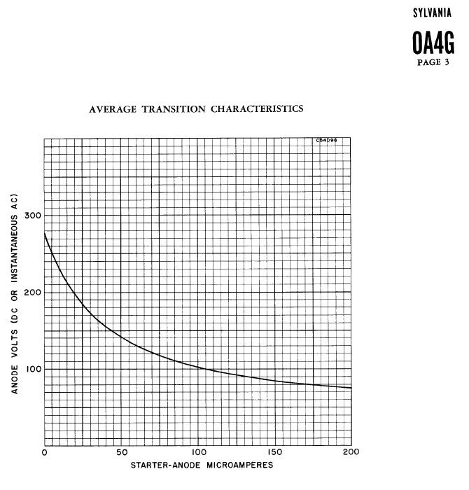
    and the cold cathode detector triode is the OA4G (neon).

    These tube types are usually plentiful and cheap. The OA4G may be a bit hard to find however. There are several miniature types of cold cathode triodes in existence but I do not remember the numbers. I would point out here that blowing them up is not very useful, they do not make them anymore.

    Finally, rather than an endless string of experiments doing "strange things" more might be gained by developing a solid theoretical concept of what we are getting into. And for the "free energy fuse box" crowd, forget it. No one is going to use wireless power transmission so she does not have to see the power line to her new "dream home" on top of the hill. Transmission of radio frequency energy for any purpose is subject to government approval, no way around it. Remember that the excuse Franklin Roosevelt, USN used to outlaw radio was the mess of jamming and interference created by electrical experimenters leading up to 1917, the day that wireless died. This can happen again in the 911 police reality, watch out.

    73 DE N6KPH


    Leave a comment:


  • garrettm4
    replied
    Equation 8, Oscillating Current Transformer

    Nhopa,

    It's as Jake said, you multiply l_0 by 4. "l_0" is the total length of your winding, if we multiply it by 4 we get the total wavelength, since we usually use a quarter wavelength for resonance, this would make the most logical sense. Next it shows to divide that quantity into the velocity of propagation, V_0, giving the frequency of oscillation, F_0, of the coil in question.

    All that sums to be this equation:

    F_0 = V_0 / ( l_0 * 4 )

    Hope that helps,

    Garrett M
    Last edited by garrettm4; 05-27-2012, 06:07 PM.

    Leave a comment:


  • jake
    replied
    Originally posted by Nhopa View Post
    The secondary coil is 20 turns designed for 1,188 Kc.
    Coil is 62 cm dia., wire used is about #17 AWG, .048" dia., coil height 6 cm. I have about 4 cm between the top of primary and the bottom of the secondary, since the instrument's impedance is 50 Ohms I will use a 1 turn test coil. Wire used for the test coil is #17 AWG, .045" dia insulated? The primary coil was removed prior to testing. Please note that using the ground connection did not make any difference in the readings.
    Test data:
    I. Test coil adjacent to bottom of secondary coil.
    1.Can 10 cm above top of secondary coil and 0 cm above 1/4" dia top
    ring.
    a) Function Generator (FG) ground connected to one end of test coil
    and field intensity meter ground: First meter movement at 0 Kc
    Second meter movement at 1,700 Kc
    b) FG ground not connected: First meter movement 402 Kc
    Second meter movement at 1,689 Kc
    2. Can 30 cm above top of secondary coil and 20 cm above 1/4" dia top
    ring.
    a) FG ground connected to one end of test coil and field intensity meter
    ground: First meter movement at 0 Kc
    Second meter movement at 1,687 Kc
    II. Test coil 3 cm below bottom of secondary coil.
    1. Can 10 cm above top of secondary coil and 0 cm above 1/4" dia top
    ring.
    a) FG ground connected to one end of test coil and field intensity meter
    ground: First meter movement at 0 Kc
    Second meter movement at 1,758 Kc
    b) FG ground not connected: First meter movement 431 Kc
    Second meter movement at 1,757 Kc
    2. Can 30 cm above top of secondary coil and 20 cm above 1/4" dia top
    ring.
    a) FG ground connected to one end of test coil and field intensity meter
    ground: First meter movement at 0 Kc
    Second meter movement at 1,763 Kc
    b) FG ground not connected: First meter movement 434 Kc
    Second meter movement at 1,760 Kc
    III. Test coil 8.5 cm below bottom of secondary coil.
    1. Can 10 cm above top of secondary coil and 0 cm above 1/4" dia top
    ring.
    a) FG ground connected to one end of test coil and field intensity meter
    ground: No meter movement at all.
    b) FG ground not connected: First meter movement 416 Kc
    Second meter does not move, but stays
    constantly about at 1 uA reading. It
    appears the movement would start above
    2Mc (out of range)
    2. Can 30 cm above top of secondary coil and 20 cm above 1/4" dia top
    ring.
    a) FG ground connected to one end of test coil and field intensity meter
    ground: No meter movement at all.
    b) FG ground not connected: First meter movement 432 Kc
    Second meter movement. See comment
    above.
    Next I will calculate coil frequencies, but I need to know what to do with the number "4" in Eric's equation no. 8.

    The easy part is almost over. The fun starts when you try to get it to do something.

    Are you grounding the coils and do you have a ground plane? Is 1188kcps a radio station in your area and how far away from it are you?

    Leave a comment:


  • Nhopa
    replied
    Tuning of the secondary coil

    The secondary coil is 20 turns designed for 1,188 Kc.
    Coil is 62 cm dia., wire used is about #17 AWG, .048" dia., coil height 6 cm. I have about 4 cm between the top of primary and the bottom of the secondary, since the instrument's impedance is 50 Ohms I will use a 1 turn test coil. Wire used for the test coil is #17 AWG, .045" dia insulated? The primary coil was removed prior to testing. Please note that using the ground connection did not make any difference in the readings.
    Test data:
    I. Test coil adjacent to bottom of secondary coil.
    1.Can 10 cm above top of secondary coil and 0 cm above 1/4" dia top
    ring.
    a) Function Generator (FG) ground connected to one end of test coil
    and field intensity meter ground: First meter movement at 0 Kc
    Second meter movement at 1,700 Kc
    b) FG ground not connected: First meter movement 402 Kc
    Second meter movement at 1,689 Kc
    2. Can 30 cm above top of secondary coil and 20 cm above 1/4" dia top
    ring.
    a) FG ground connected to one end of test coil and field intensity meter
    ground: First meter movement at 0 Kc
    Second meter movement at 1,687 Kc
    II. Test coil 3 cm below bottom of secondary coil.
    1. Can 10 cm above top of secondary coil and 0 cm above 1/4" dia top
    ring.
    a) FG ground connected to one end of test coil and field intensity meter
    ground: First meter movement at 0 Kc
    Second meter movement at 1,758 Kc
    b) FG ground not connected: First meter movement 431 Kc
    Second meter movement at 1,757 Kc
    2. Can 30 cm above top of secondary coil and 20 cm above 1/4" dia top
    ring.
    a) FG ground connected to one end of test coil and field intensity meter
    ground: First meter movement at 0 Kc
    Second meter movement at 1,763 Kc
    b) FG ground not connected: First meter movement 434 Kc
    Second meter movement at 1,760 Kc
    III. Test coil 8.5 cm below bottom of secondary coil.
    1. Can 10 cm above top of secondary coil and 0 cm above 1/4" dia top
    ring.
    a) FG ground connected to one end of test coil and field intensity meter
    ground: No meter movement at all.
    b) FG ground not connected: First meter movement 416 Kc
    Second meter does not move, but stays
    constantly about at 1 uA reading. It
    appears the movement would start above
    2Mc (out of range)
    2. Can 30 cm above top of secondary coil and 20 cm above 1/4" dia top
    ring.
    a) FG ground connected to one end of test coil and field intensity meter
    ground: No meter movement at all.
    b) FG ground not connected: First meter movement 432 Kc
    Second meter movement. See comment
    above.
    Next I will calculate coil frequencies, but I need to know what to do with the number "4" in Eric's equation no. 8.

    Leave a comment:


  • jake
    replied
    Originally posted by Nhopa View Post
    Thank you Eric for the review. I have a question on equation (8) in your post #404. Calculating Fo=Vo/(lo?4) for the extra coil, what is that symbol front of the number "4"?
    It's a big fat dot. I think you should multiply there. Its the only thing that makes sense.

    What are you using for a ground? And how are you connecting it?

    Leave a comment:


  • Nhopa
    replied
    Theory of Wireless Power Equations

    Originally posted by T-rex View Post
    Nhopa post #528

    This gives the experimentally determined correction factor to the basic design equation.

    73 DE N6KPH
    Thank you Eric for the review. I have a question on equation (8) in your post #404. Calculating Fo=Vo/(lo?4) for the extra coil, what is that symbol front of the number "4"?

    Leave a comment:


  • David G Dawson
    replied
    Originally posted by madhatter View Post
    If you go over to archive.org and search Glasoe, you'll find the book Pulse Generators. It's a BIG book but worth having. That should be the same MIT book.

    As it's volume 5 of the LAB series I'd love to see what the others are.
    Madhatter,
    See attached for the complete MIT series.
    I have dowloaded all books up to Book 7 plus a few others, Crystals and Vacuum Tubes.

    Smokey
    Attached Files

    Leave a comment:

Working...
X